Ed Nisley's Blog: Shop notes, electronics, firmware, machinery, 3D printing, laser cuttery, and curiosities. Contents: 100% human thinking, 0% AI slop.
So my trustySony DSC-H5 camera emitted a horrible crunching sound from inside its lens assembly, spat out several error codes which boiled down to “throw me out”, stopped retracting its lens, and developed a nasty rattle. If I thought dropping $2k on a fancy mirrorless DSLR would improve my photography, I’d do it, but instead I picked up a $60 used DSC-H5 from eBay and continued the mission.
Of course, the new-to-me H5 suffers from the half-press switch failure common to that entire line of Sony cameras; my DSC-H1 repair notes still come in handy for many folks.
I’d preemptively repaired the shutter button + switch in my now-defunct H5, so I dismantled it, extracted the control assembly + shutter button, bulldozed the debris aside, dismantled the new(er) H5, transplanted the parts, reassembled it, and declared victory.
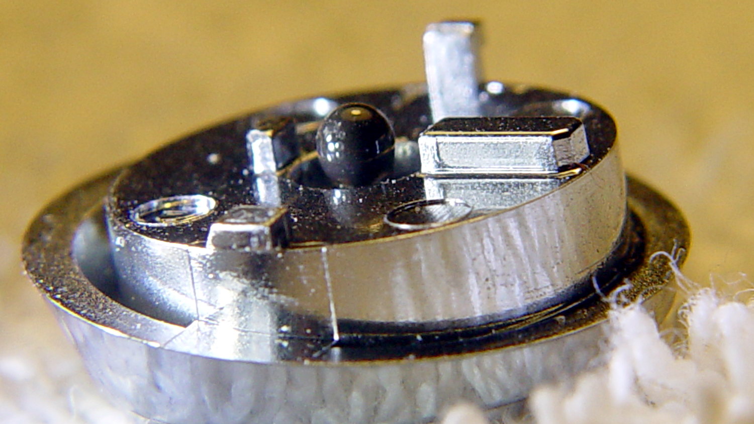
Which left me with a pile of parts that could become an H5, if I could fix the lens assembly, which seemed unlikely. While pondering the futility of human existence, I applied a low-effort repair to the defunct shutter button by scuffing the nicely chromed and absurdly tapered tip of the OEM shutter button’s shaft, then applying a dot of JB Kwik epoxy:
DSC-H5 Shutter Button – epoxy dot
The nice sphere came from hanging downward, with the button sitting atop a short brass tube on the workbench.
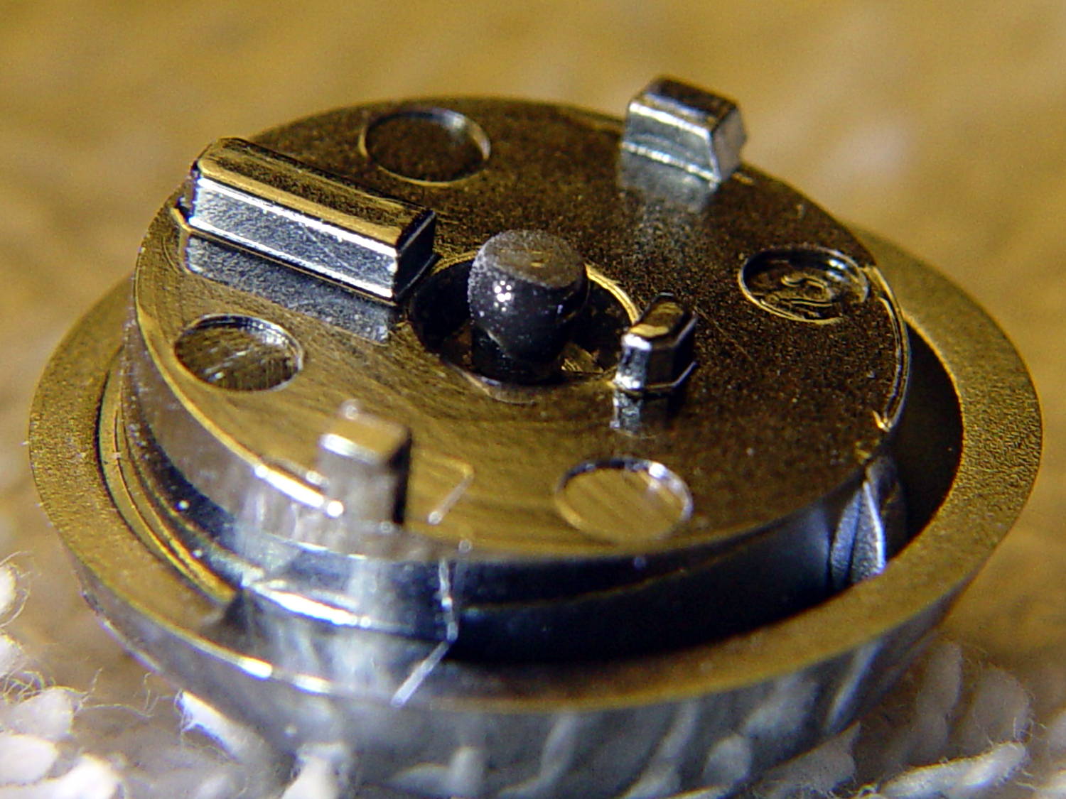
Filing the dot’s end flat produced a blunt plunger much larger than the OEM tip:
DSC-H5 Shutter Button – filed epoxy dot
You can just see the edge of the OEM tip inside the grayish end, which puts the filed flat at the original pin’s length.
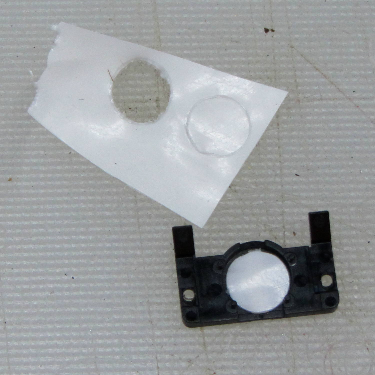
I punched a new plastic disk to replace the indented one:
DSC-H5 – shutter switch cover
Based on past experience, the new plunger tip will work fine, although, unlike the brass screw repair, the OEM plastic pin can still break and launch the spring-loaded shutter button cap into a nearby bush. Given that I may never actually use the repaired button, I’ll take the risk.
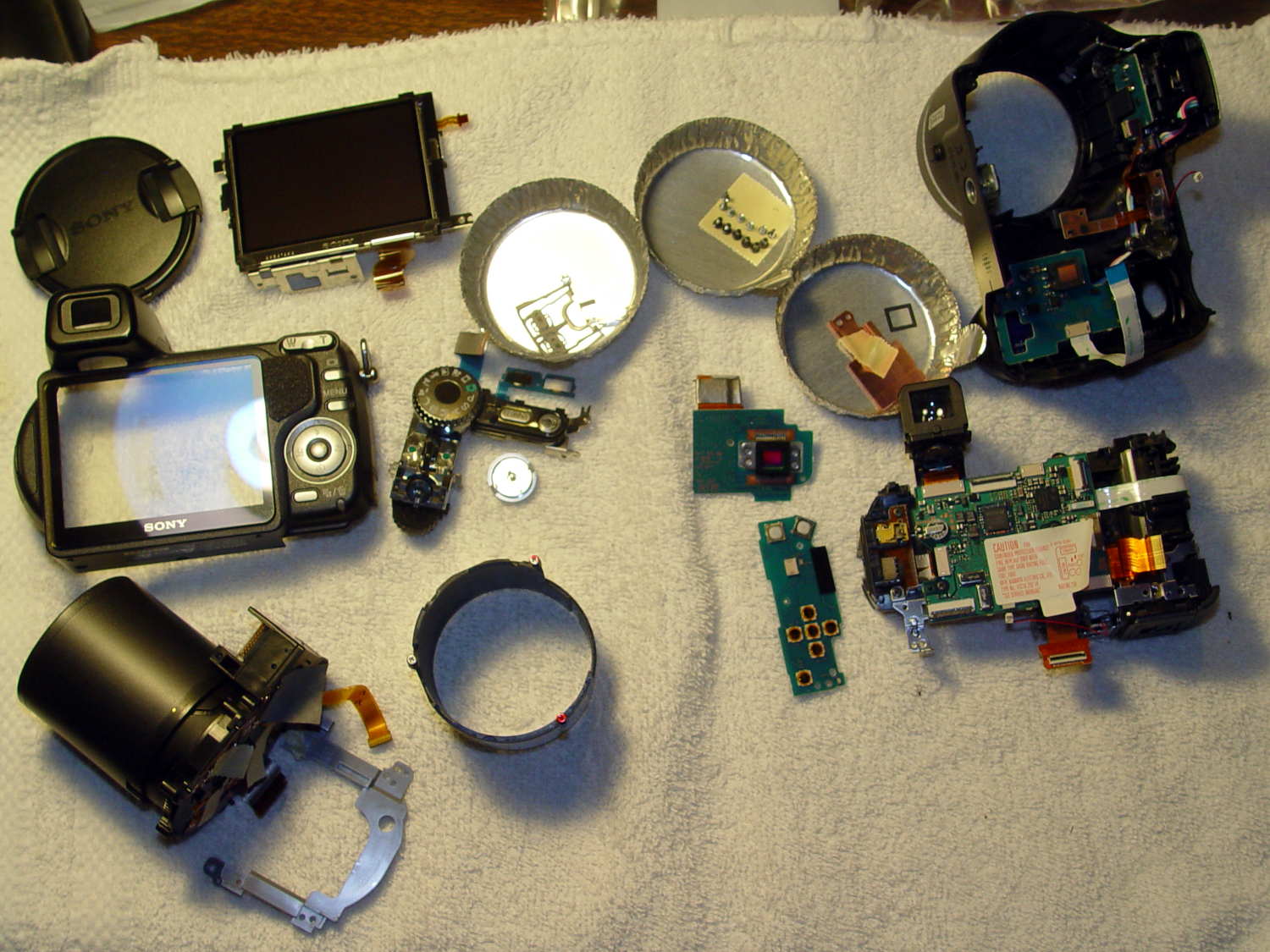
Finding out if the new tip will work may take a while:
DSC-H5 – disassembled
I did a bit more disassembly than strictly necessary to replace the shutter button, but not by much; you’d be crazy to pay me to fix your camera, fer shure.
A pair of torchiere lamps lit the living room for many, many years:
Torchiere Lamp Shade – original
During their tenure, they’ve gone from 100 W incandescent bulbs to “100 W equivalent” CFL curlicues to “100 W equivalent” warm-white LED bulbs. The LEDs aren’t up to the brightness of the original incandescents, but you can get used to anything if you do it long enough.
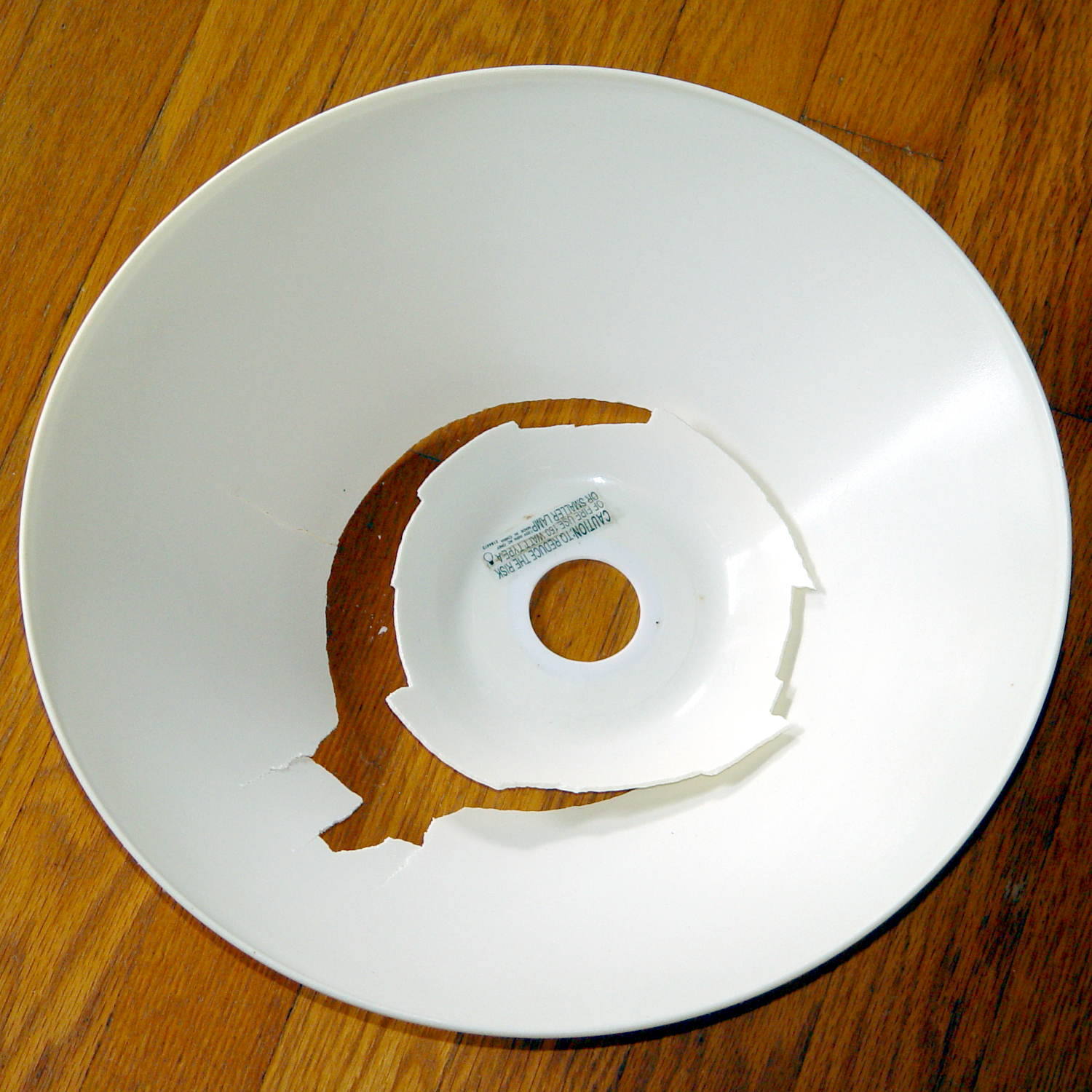
After so many years, the plastic shades / diffusers became brittle:
Torchiere Lamp Shade – original broken
That’s after a bump, not a fall to the floor. So it goes.
Some casual searching didn’t turn up any likely replacements. The shade measures 14 inch = 355 mm across the top, far too large for the M2’s platform, but maybe a smaller shade in natural PETG would work just as well.
ACHTUNG! This is obviously inappropriate for the original incandescent bulbs and would be, IMO, marginal with CFL tubes. Works fine with LEDs. Your mileage may vary.
OpenSCAD to the rescue:
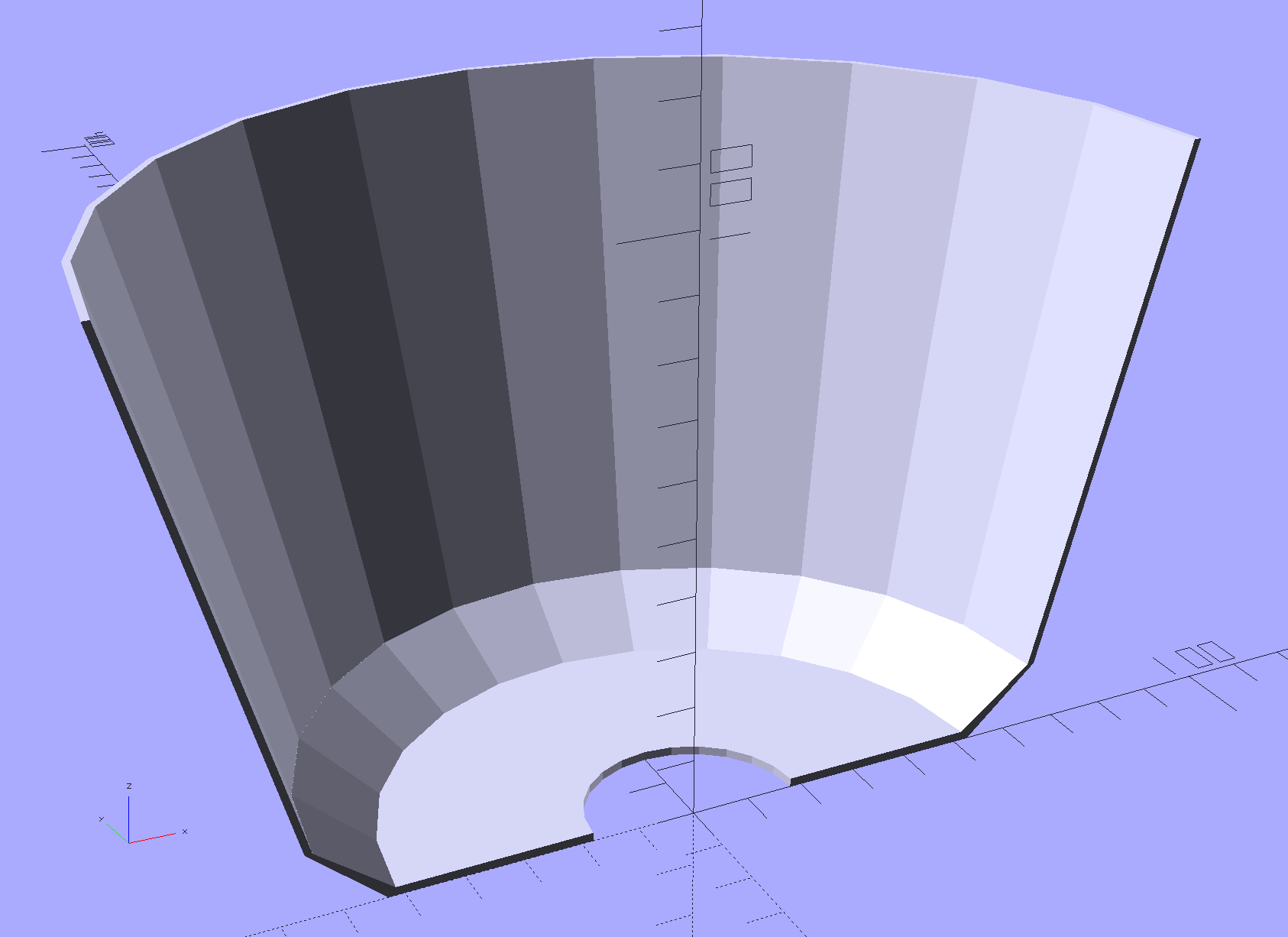
Torchiere Lamp Shade – section
That’s a section down the middle. The top is 180 mm across, leaving 20 mm of general caution on the 200 mm width of the platform. The section above the sharply angled base is 90 mm tall to match the actual LED height, thereby putting them out of my line-of-sight even when standing across the room.
I ran off a short version, corrected the angles and sizes for a better fit, tweaked the thickness to fuse three parallel threads into a semitransparent shell, and …
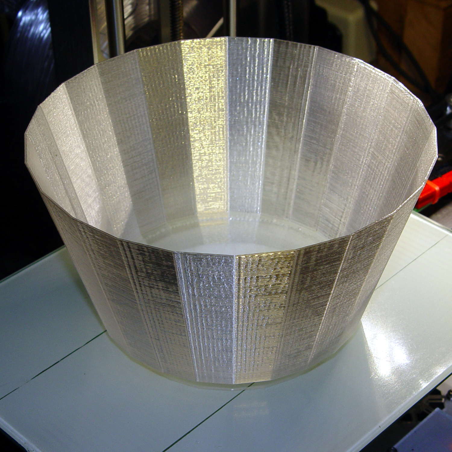
Torchiere Lamp Shade – M2 platform
Producing what looks like thin flowerpot required just shy of seven hours of print time, as it’s almost entirely perimeter, goin’ down slow for best appearance. The weird gold tone comes from the interaction of camera flash with warm-white CFL can lights over the desk.
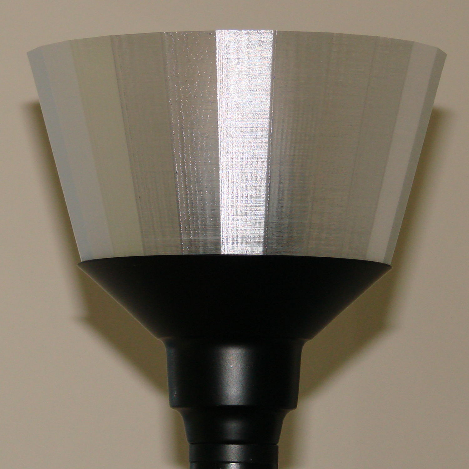
If you hadn’t met the original, you’d say the new shade grew there:
Torchiere Lamp Shade – no epoxy
It’s definitely a Brutalist design, not even attempting to hide its 3D printed origin and glorying in those simple geometric facets.
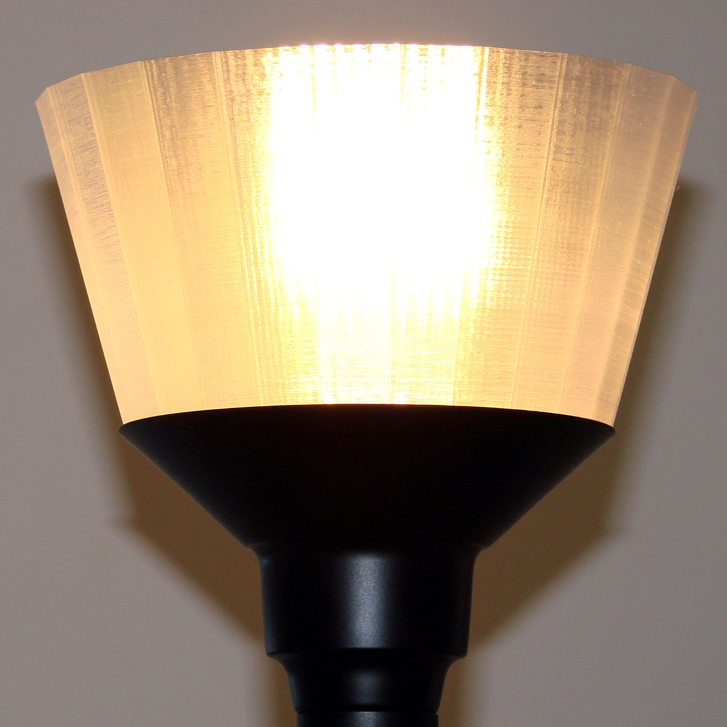
Those three threads of natural PETG makes a reasonably transparent plate, clear enough that the bulb produced an eye-watering glare through the shade:
Torchiere Lamp Shade – no epoxy – lit
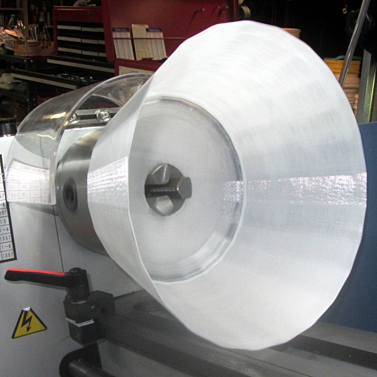
So I returned it to the Basement Laboratory, chucked it up in the lathe (where it barely clears the bed), dialed the slowest spindle speed (150 rpm according to the laser tach, faster than I’d prefer), and slathered a thin layer of white-tinted XTC-3D around the inside:
Torchiere Lamp Shade – lathe spinning
For lack of anything smarter, I mixed 2+ drops of Opaque White with 3.1 g of Part A (resin), added 1.3 g of Part B (Hardener), mixed vigorously, drooled the blob along the middle of the rotating shade, spread it across the width using the mixing stick, smoothed it into a thin layer with a scrap of waxed paper, and ignored it for a few hours.
If the lathe perspective looks a bit weird, it’s perfectly natural: I raised the tailstock end enough to make the lower side of the shade just about horizontal. Given the gooey nature of XTC-3D, it wasn’t going anywhere, but I didn’t want a slingout across the lathe bed.
The lit-up result isn’t photographically different from the previous picture, but in person the epoxy layer produces a much nicer diffused light and no glare.
I might be forced to preemptively replace the other shade, just for symmetry, but we’ll let this one age for a while before jumping to conclusions.
This file contains hidden or bidirectional Unicode text that may be interpreted or compiled differently than what appears below. To review, open the file in an editor that reveals hidden Unicode characters.
Learn more about bidirectional Unicode characters
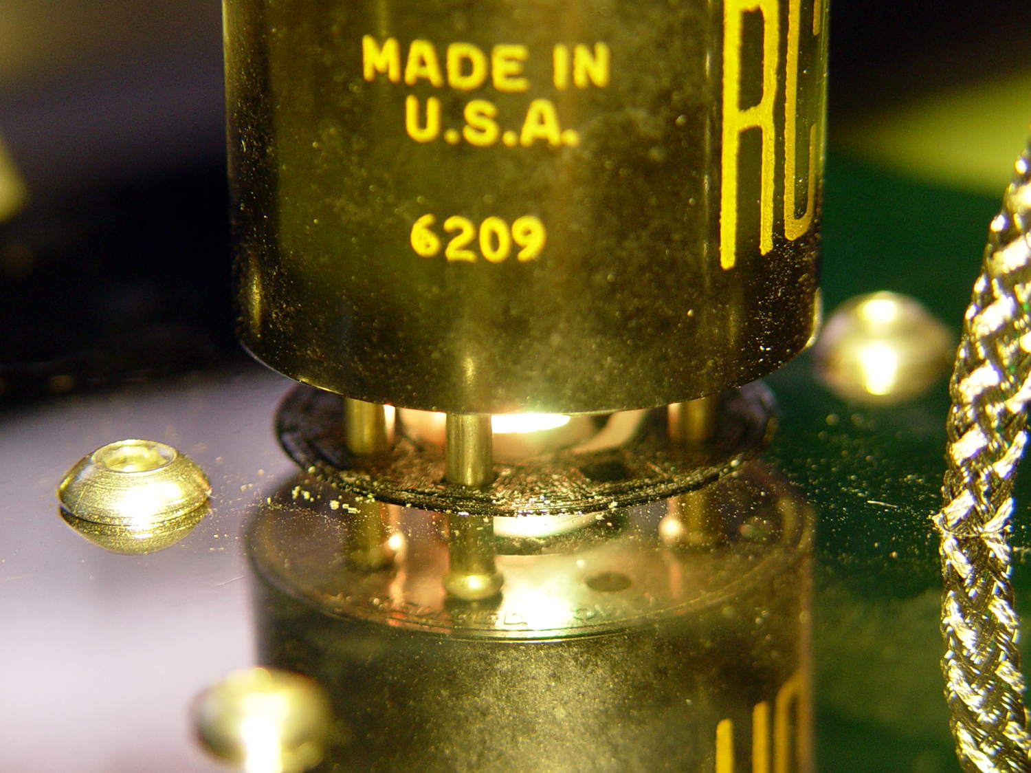
The LEDs adorning the 0D3 rectifier tube became unreliable:
0D3 Octal – 25 mm socket – raised LED
After failing to plug in a different USB power supply, a close look at the USB connector showed the problem:
Knockoff Arduino Nano – broken Mini-B connector
A bit of needle-nosetweezering extracted the culprit from the power supply’s connector:
Knockoff Arduino Nano – broken Mini-B connector – fragment
I tried applying the world’s smallest dot of epoxy to the fracture, probably slobbered epoxy along the pins while reinserting it, and the Nano still doesn’t light up.
Given that knockoff Nano boards cost a touch over two bucks delivered, it’s not clear transplanting a connector from one of the never-sufficiently-to-be-damned counterfeit FTDI USB adapters makes any sense.
Some weeks ago, the APRS + voice adapter on my radio began randomly resetting during our rides, sending out three successive data bursts: the TinyTrak power-on message, an ID string, and the current coordinates. Mary could hear all three packets quite clearly, which was not to be tolerated.
I swapped radios + adapters so that she could ride in peace while I diagnosed the problem, which, of course, was both intermittent and generally occurred only while on the road. The TinyTrak doc mentions “… a sign of the TinyTrak3 resetting due to too much local RF energy”, so I clamped ferrite cores around All! The! Cables! and the problem Went Away.
Removing one core each week eventually left the last core on the GPS receiver’s serial cable, which makes sense, as it plugs directly into the TT3. The core had an ID large enough for several turns (no fool, I), another week established a minimum of three turns kept the RFI down, so I settled for five:
KG-UV3D APRS – ferrite on TT3 GPS cable
Prior to the RFI problem cropping up, nothing changed. Past experience has shown when I make such an assertion, it means I don’t yet know what changed. Something certainly has and not for the better.
I swapped the radios + adapters and all seems quiet.
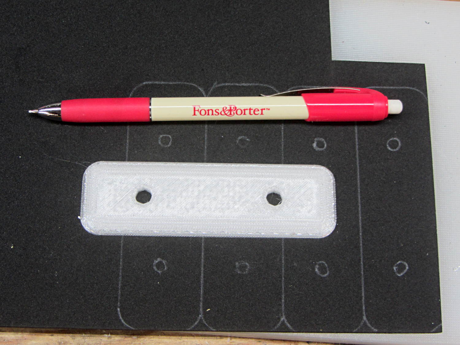
This worked surprisingly well to lay out black foam gaskets for new fairing mounting plates:
Black foam layout with ceramic fabric pen
Mary uses the Fons & Porter Mechanical Pencil to mark quilting patterns on fabric. It has, they say, a “strong ceramic 0.9MM white lead” with “water-soluble dyes” capable of both laying down a durable mark and washing out without leaving a trace. I don’t care about the latter, of course, but it did brush off reasonably well.
The next step involved running an X-Acto knife around the perimeter of the plate and punching the holes.
You can get colored ceramic leads (for small values of color) for use on other backgrounds.
With the information you shared, we were able to successfully model and reconstruct the drive wheel in only a couple of days.
One useful thing we discovered is there’s a lot of room for error – so long as the pin catches and the wheel isn’t slipping on the motor shaft, the mechanism will work. The grooves and the interior radius of the original part aren’t critical.
Because of your heads up about Geneva wheels, I found this excellent website – https://newgottland.com/2012/01/08/make-geneva-wheels-of-any-size/ – which includes a link to a Geneva wheel calculator. With the measurements you sent and a measurement off of the pen carousel, the calculator generated near perfect dimensions for a replacement. There was a little sanding and rounding to fit but it was certainly within tolerance.
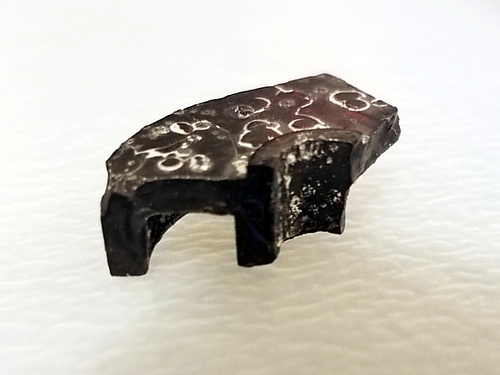
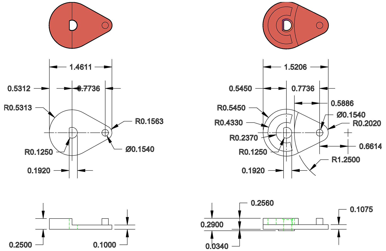
Interestingly, the pieces of the drive wheel that I pulled out of the case revealed a small hidden detail. On the underside, there’s a collar around the motor shaft that gives the cam an extra ~.03″ thickness. Presumably this is to help reduce friction during travel. Our prototype doesn’t take this detail into consideration – we’ve had no issues with friction, and we compensated for the thickness by making the pin a little longer – but it’s meaningful to note.
HP7475A Carousel Drive – cam1
The broken pieces also confirmed the thicknesses and radii of the original part, and so my partner was able to build an accurate technical drawing of the drive wheel for future fabrication.
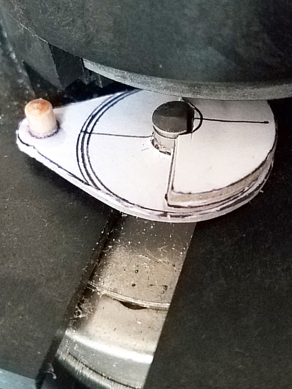
While we intend to make a better replacement, our prototype was built with dense 1/8″ mat board, PVA glue, binder clips, and a short piece of wooden dowel from our bits box. Basically just stuff we had kicking around the studio. It’s held up shockingly well. A little dented around the edges from hitting the carousel, but there’s no slippage. I’m thinking I’ll use it until it falls apart, just to see how long it takes.
HP7475A Carousel Drive – repaired – cam2
Attached, find a technical drawing comparing the original drawing to our prototype (measured in good old fashioned 1980s inches); a photo of the retrieved piece, showing the collar on the reverse side; and a photo of the prototype in place. Feel free to share these – everyone deserves a working plotter!
7475a drive wheel
Once the carousel was working, my roommate – an electrical engineer – hooked me up with a custom serial cable, a Raspberry Pi, and a crash course in Python, so now that I can communicate with the plotter, the possibilities are staggering. I’m thrilled to add this machine to my print studio arsenal!