This took entirely too long to figure out:
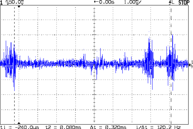
That’s with the scope probe ground clip connected to the wall wart coax connector barrel and the scope probe tip on the ground clip. It’s not the noise on the 24 VDC supply, it’s the noise injected into the ground connection!
Huh. Makes it tough to sort out low-level signals, it does indeed.
Consider one of my bench power supplies at 24 V:
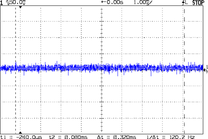
Nice & quiet, the way power should be. One might quibble about the residual noise, but at least it’s not blasting out horrific bursts at 120 Hz.
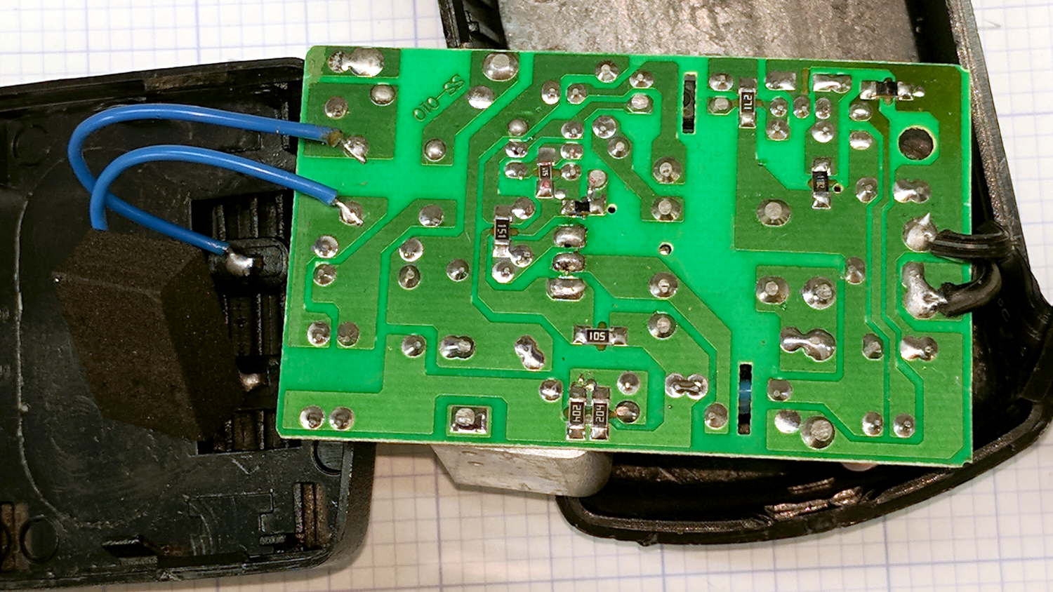
For completeness, the PCB inside the offending SMAKN 24 V wall wart:
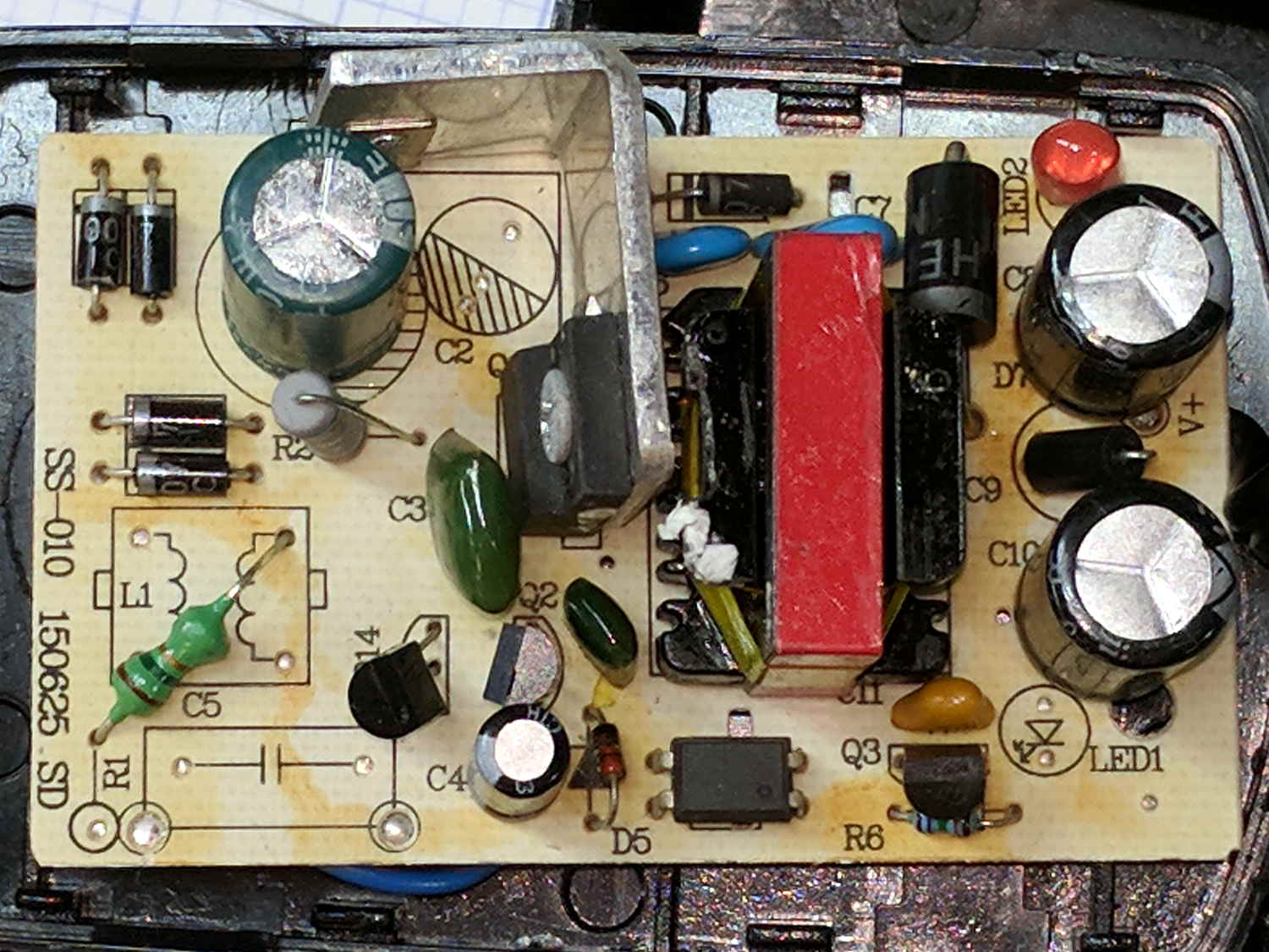
“High Quality Commercial Grade” my aching eyeballs.
[Update: Edits based on eagle-eyed observations in the comments. ]
Not as many missing components as I expected, though, if the truth be told. The missing transformer common-mode choke seems odd and, AFAICT, the resistor inductor angling out from the R1 callout doesn’t connect to anything, connects directly to the AC line because C5 is missing and the pad joining them doesn’t go anywhere else it replaces the jumper (?) to the bottom-left pad and the missing parts. The red LED in the upper right isn’t visible through the black case, although it might serve as a voltage regulator.
Over on the far right, beyond the transformer and between the two capacitor cans, is a component marked C9 with an oddly angled part. Seen from the other end, it’s a ferrite bead:
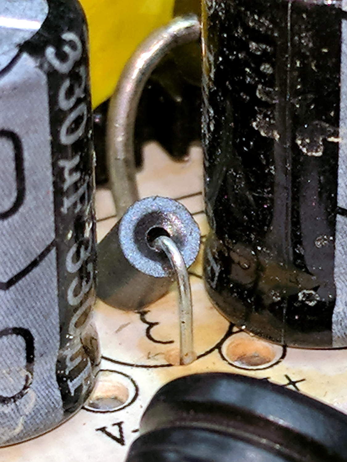
I don’t know why that spot has an inductor symbol with a capacitor part callout.
The other side of the PCB looks clean:
It’ll probably serve well in a noise-tolerant application, maybe an LED power supply.
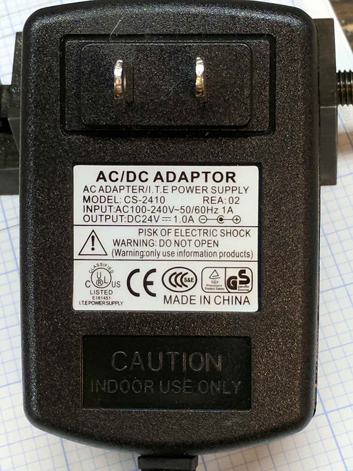
As pointed out in the comments, there’s a UL mark:
Not sure what I’ll replace it with, although a small 24 V power supply brick may suffice.

Comments
7 responses to “60 kHz Preamp: Power Supply Noise”
I have a mid-80s vintage Hafler power amplifier that came out of storage a year ago. Seemed OK after sitting a dozen years, but its power supply noise makes it difficult to use with the AM tuner in the shop (FM reception is hampered by the steel siding and the iron-rich ridge in line of sight…) I’ll have to see if the really old HP 1MHz scope can shed some light on the issue. It would be a bit early for capacitor plague, but an eyeball inspection is called for.
Eh? What’s that on the lower left side of the label? A check of a couple pieces of Chinese gear shows the same logo…
It could be legit:
How to identify counterfeit UL mark
Moderately good production values, but the “company name” is a sticker on the other side.
The “transformer” would be a common mode inductor, to keep from propagating switching noise back out to the AC line. Looks like they replaced it with a small series inductor (looks like a green resistor) on one lead.
Exactly. In fact, it looks like the original AC line entry point was next to C5 at the bottom of the board. C5 must have been a line-voltage rated bypass cap; L1 the common-mode inductor as madb noted; and R1 originally seems to have been an inrush limiting thermistor. But all of those parts got chopped to cut costs, RFI be damned.
Well it does say (P)ISK OF ELECTRIC SHOCK on the label and you seem shocked with what’s inside… I’d say it does exactly what the label claims :)
I was pretty shocked myself the other day, when a package from banggood arrived with a crumpled piece of paper containing text that actually passed for correct English. It seems world is coming to an end :)
If I am not mistaken, C7 couples the rectified line voltage node through the ferrite bead to the V+ output node. Possibly a misguided bypassing attempt that will end up injecting more noise than it suppresses? Seems like a path for those ringing waveforms at twice the line frequency that you observed.
[…] eventually noticed the yellow LED indicating +24 V input from the power supply (previously, a noisy wall wart) was dark. Poking around revealed I’d inadvertently installed a 1 kΩ ballast […]