Encouraged by the simulation, the 60 kHz preamp hardware sprawls over a phenolic proto board:

The inductors and resistors hanging off the screw terminals produce more-or-less the same impedance as the real loop antenna. The alligator clips connect a function generator to the secondary winding of a current transformer (used backwards), thus injecting a wee differential signal into the “antenna”.
The clump of parts in the lower left knock the 24 VDC wall wart down to 20 V and produce a 10 V virtual ground in the middle:
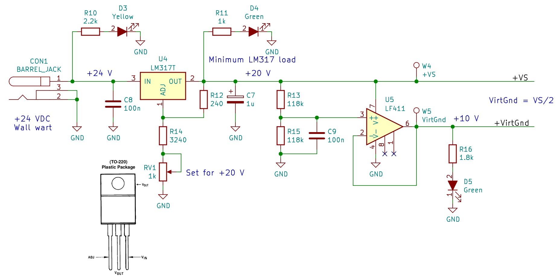
The LEDs give a cheerful indication that the power supplies have reported for duty, plus apply a minimum load to the LM317 while I was tinkering. The heatsink gets tolerably warm, so I should dial back or disconnect the LEDs to reduce the load.
The preamp hardware matches the simulated layout, with a few extra bits tossed in:

The weird values come from whatever 1% resistors and silver-mica caps emerged from the heap. The 27 V Zener diodes and 5 kΩ resistors may or may not protect the instrumentation amp inputs from lightning-induced transients.
Because the HP8591 analyzer’s tracking generator starts at 100 kHz, I fed the DDS function generator into the preamp, manually stepped the frequency in 250 Hz increments, and had the analyzer show the maximum response of 19 separate sweeps:

That was tedious and, no, it’s not a comb filter: the actual response skates across the peaks of all those bumps.
The marker shows the preamp bandwidth is 2 kHz, roughly what the simulation predicts; the extremely tight span of that plot makes it look a lot flatter that the usual presentation.
Tightening the span even more shows an unexpected effect:

Those sidebands at ±120 Hz (probably) come from power-line magnetic fields into the “antenna”, because the magnetic field strength depends on the absolute value of the voltage. If they came from the signal generator, they’d be at ±60 Hz: the waveform amplitude depends directly on the voltage.

Comments
2 responses to “60 kHz Preamp: First Pass”
[…] cleaned up version of my trusty circuit board holder now keeps the 60 kHz preamp off what passes for a floor in the […]
[…] 60 kHz tuned preamp […]