Ed Nisley's Blog: Shop notes, electronics, firmware, machinery, 3D printing, laser cuttery, and curiosities. Contents: 100% human thinking, 0% AI slop.
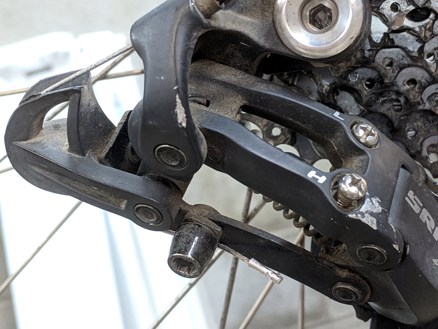
With more snow on the schedule, Mary’s bike finally got a new rear shifter:
Tour Easy – SRAM X.0 grip shifter installed
It’s an old-school SRAM X.0 grip shifter, evidently compatible with SRAM X.9 and X.7 derailleurs, and seems to work OK. The wavy ridges may be more prominent than necessary for our road riding, though.
In a miracle of rare device, the preinstalled cable turned out to be exactly long enough:
Tour Easy – SRAM X.0 cable length
Twiddling the length for perfect shifting requires on-the-road testing and the chain wrap may need tweaking (I may not have gotten it right when I installed the derailleur), but at least the shifter stops at every detent along the way.
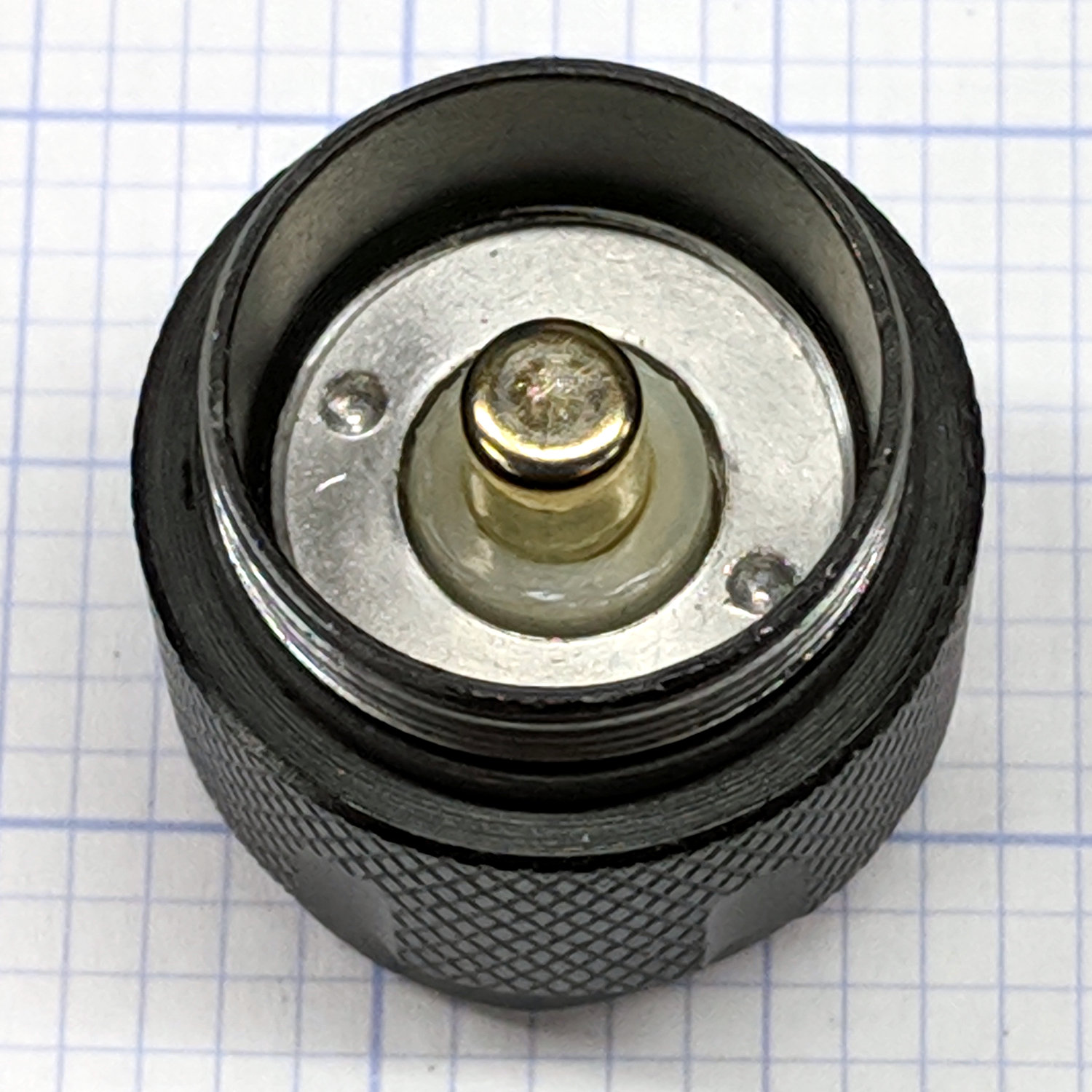
Mashing the LED PCB into place didn’t entirely solve the weak beam problem, so I unscrewed the tailcap holding the switch on the other end of the body:
J5 Tactical Flashlight – tailcap
Unscrewing the lock ring releases the switch assembly:
J5 Tactical Flashlight – tailcap parts
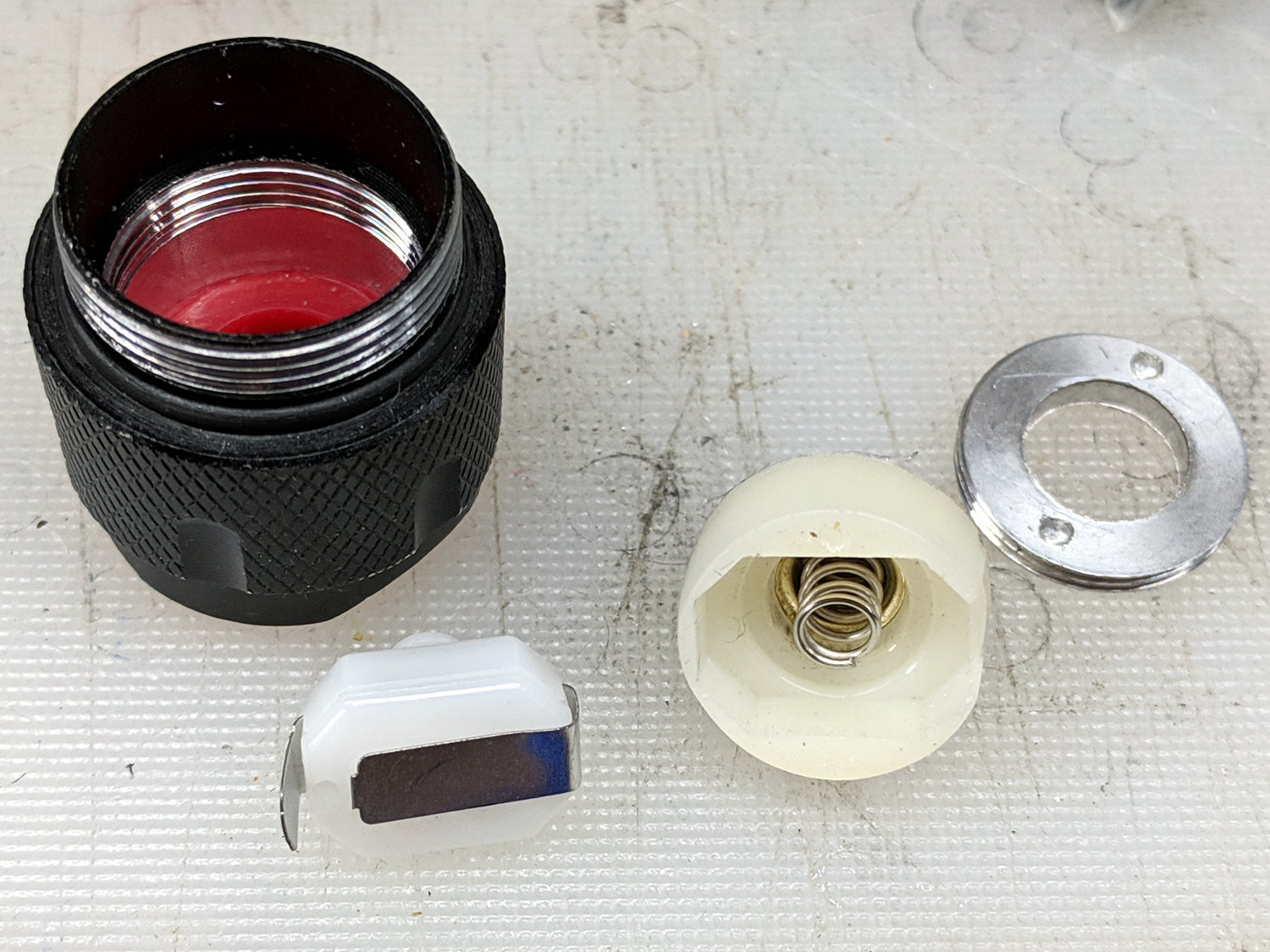
I suspect the tab sticking out from the side of the switch doesn’t make / never made good contact with the aluminum tailcap body, but having gone this far there’s no reason to stop. The plastic housing around the spring-loaded brass battery contact pops off to reveal the actual switch:
J5 Tactical Flashlight – switch contacts
The long tab on the front of the switch sits under the spring, so that’s the negative battery contact. The LED current goes through:
battery negative to contact + spring
switch tab + moving contact + tab
tab to tailcap pressure fit
tailcap threads
front tube threads
LED pill to PCB
spring to battery positive
So. Many. Aluminum. Joints.
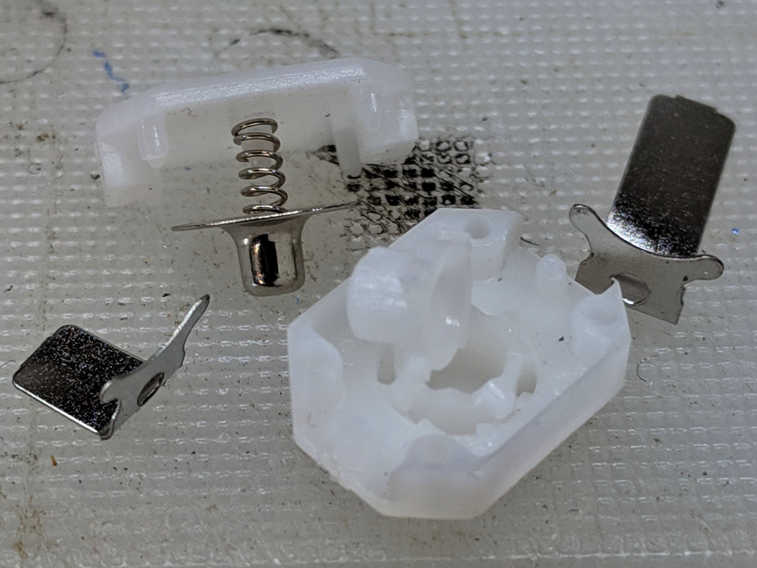
The switch body snaps apart to disgorge a remarkable number of parts:
J5 Tactical Flashlight – tailcap switch parts
Nothing looked out of order, so I applied a thin layer of DeoxIT Red to all the contacting parts and reassembled everything.
For the record, the switch’s internal parts have many plausible assembly sequences; the workable one goes a little something like this:
J5 Tactical Flashlight – tailcap switch contacts
Contrary to what you (well, I) might think, the switch is off when the central contact is pushed forward, away from the side contacts.
I bent a slight angle into the tailcap contact (on the right in the picture) to make better / firmer contact with the tailcap body, cleaned all the threads with a cotton swab carrying a dab of DeoxIT, and screwed it all together.
With everything back together, the beam seems bright and steady again. We’ll see how long it lasts.
I’ve been using the J5 Tactical flashlight as a “walking light” on our walks around the neighborhood, because its bright white spot has definitely caused a few drivers to look up from their phones at the last moment and swerve away.
Of late, however, it turned on with a weak light and operated erratically. Removing the lens and unscrewing the front end revealed one mmmm potential problem:
J5 Tactical Flashlight – loose LED PCB
It looks like they’re depending on the “gold” in cutaway plated-through holes to make electrical contact with the aluminum mount, then through the threads to the case. The PCB joint would work much better with consistent pressure all the way around its perimeter.
I mashed the PCB into place with a machinists vise, but, given the number of problems I’ve had with J5 flashlights (one a QC reject), they’re on my Non-Preferred Vendor list; if I’m going to get junk, I may as well pay bottom dollar.
Unsolder the strap in the middle and the B+ positive connection on the right side to remove the cells.
If cameras used bare cells, rather than glued-shut “proprietary” packs with super-secret unique ID ROMs, they’d be easier to keep running. My Sony DSC-H5 has other problems, but NiMH AA cells are easy to find.
The dotted lines show the results from late 2015 for a pair of then-new Wasabi NP-BX1 batteries, so the DOT-01 batteries look about the same. The F battery barely lasted to the halfway point of our most recent bike ride and the G battery now resides in the blinky-and-glowy pile.
I’d be unsurprised to discover all the myraid “different” NP-BX1 batteries all come from the same factory. Unlike the Wasabi batteries, these lack date codes, which seems like an extra-cost option you don’t get on the low end.
After nearly four years of dangling a bare millimeter above the nozzle, the lever on the relocated Z-Axis switch finally snagged a stray thread and got bent out of shape. I un-bent it, but finally decided it was time to get more air between the nozzle and the switch actuator.
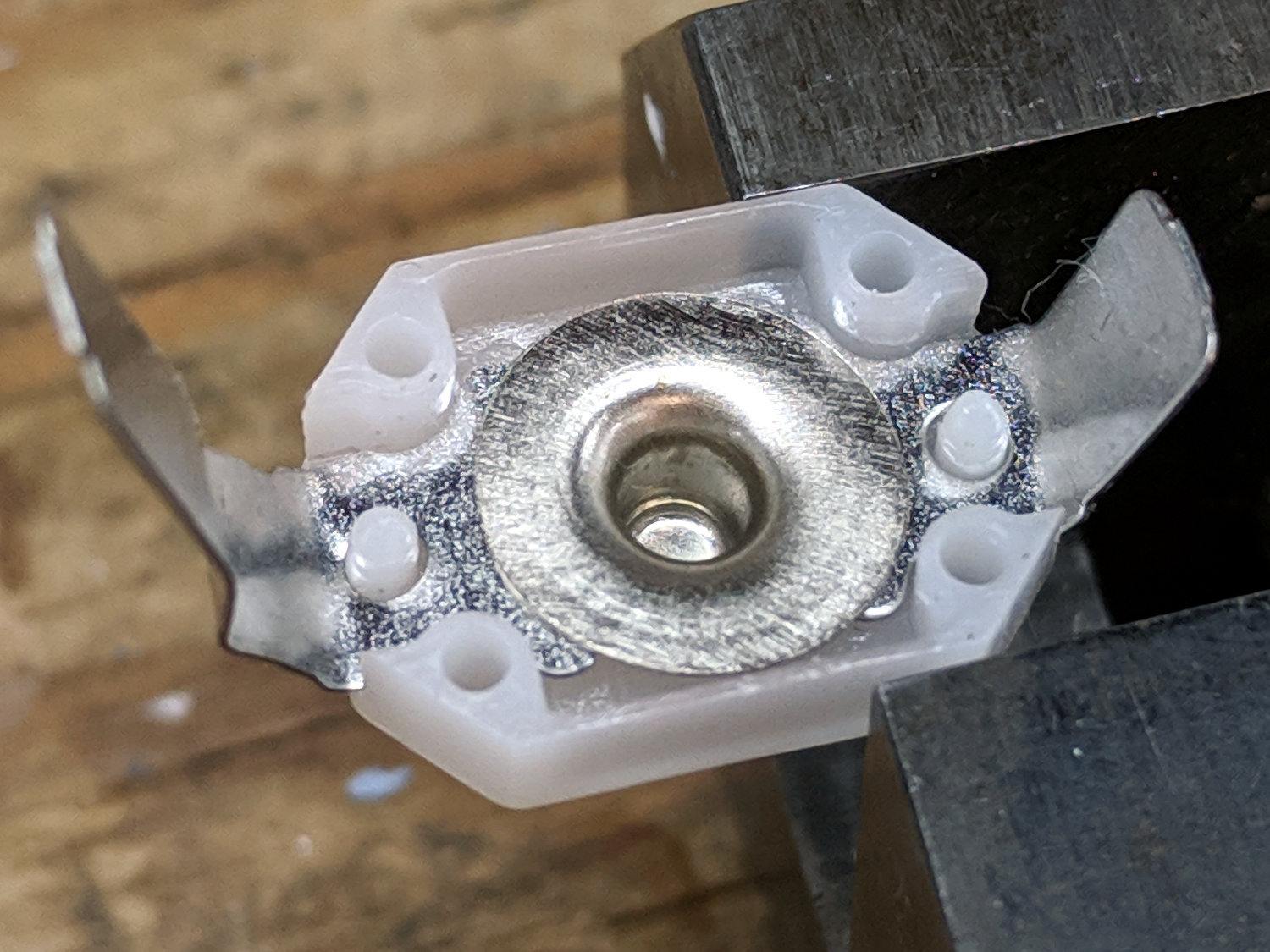
Prying the ends outward with a thumbnail releases a pair of snaps and the cover pops off to reveal the innards:
M2 Z-Axis – microswitch interior
The spring-loaded innards will launch themselves into the far corners of your shop, so be gentle as you slide the lever out and reinstall the side plate with a pair of clicks.
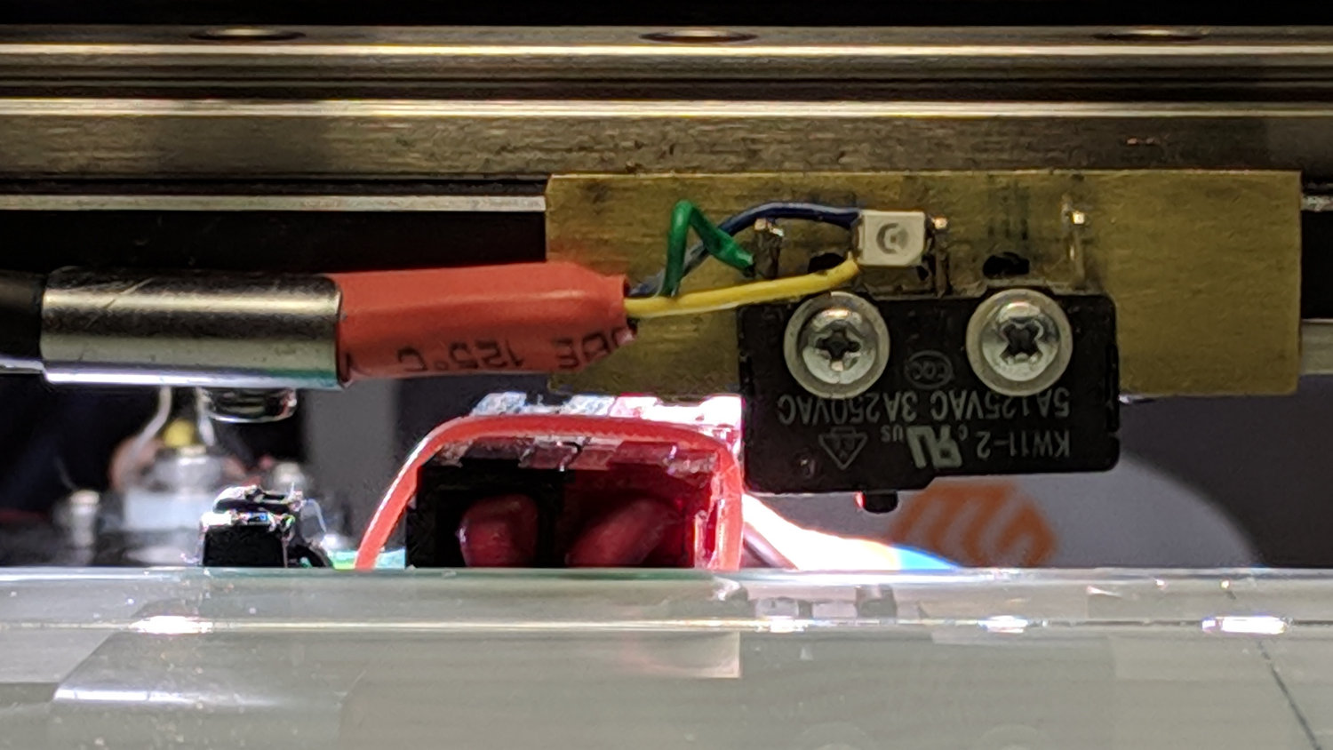
I filed the screw holes in my homebrew brass angle plate into slots, so as to get some adjustability, remounted the switch on the X-axis gantry, and tuned for best clearance:
M2 Z-Axis – bare microswitch vs nozzle
It looks a bit more canted than it really is.
There’s about 1.6 mm of Z-axis distance between the nozzle and the switch, which should suffice for another few years.
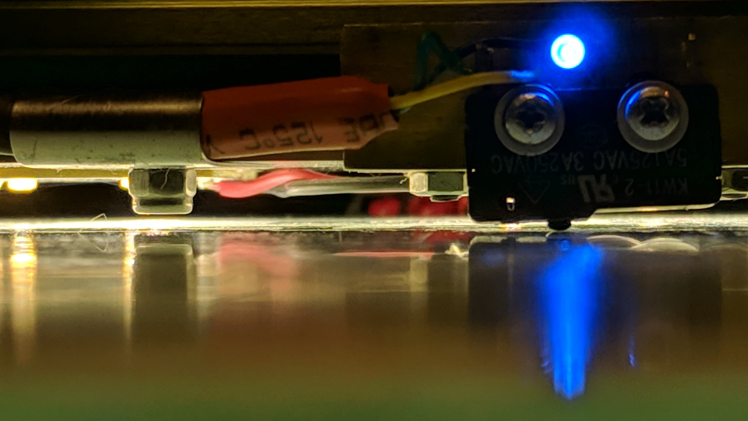
The view from the front shows a slight angle, too:
M2 Z-Axis – activated
There’s a millimeter or so below the nuts holding the X-axis linear slide in place, because the original 18 mm M3 SHCS are now 16 mm long (having shotgunned the metric SHCS and BHCS situation some time ago) and the washers are gone.
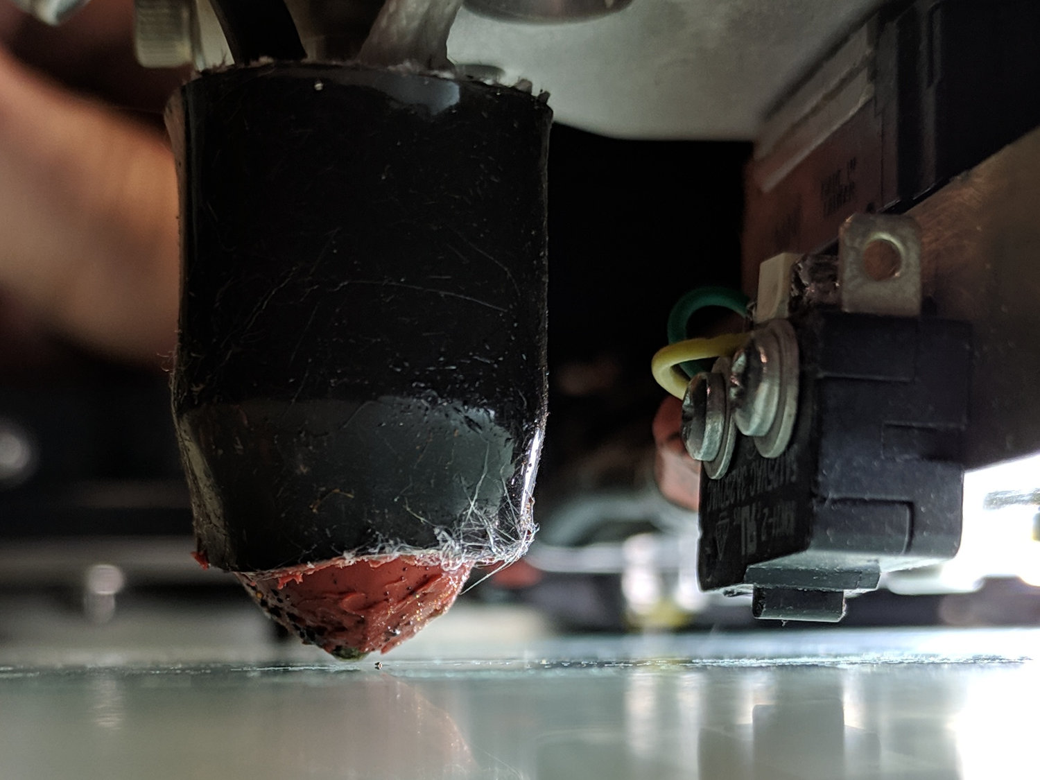
They’re all nylon lock nuts except for the one just to the left of the switch, providing barely enough clearance for the Powerpole connectors on the hotrod platform:
M2 Z-Axis – platform connector clearance
With the nozzle off the platform to the far right side, Z-axis homing proceeded normally. Manually jogging to Z=+5.0 mm left 2.6 mm of air under the nozzle, so I reset the offset in EEPROM to -2.4 = (2.6 – 5.0) mm:
M206 Z-2.4
M500
The first calibration square came out at 2.91 mm, so I changed the offset to -2.3 mm, got a 2.80 mm square with a firmly squished first layer, changed it to -2.5 mm, and got a 3.00 mm square for my efforts.
An array of five squares showed the platform remains level to within +0.05 / -0.07 mm:
M2 Platform Alignment Check – 2019-02-06
I defined it to be Good Enough™ and quit while I was ahead.
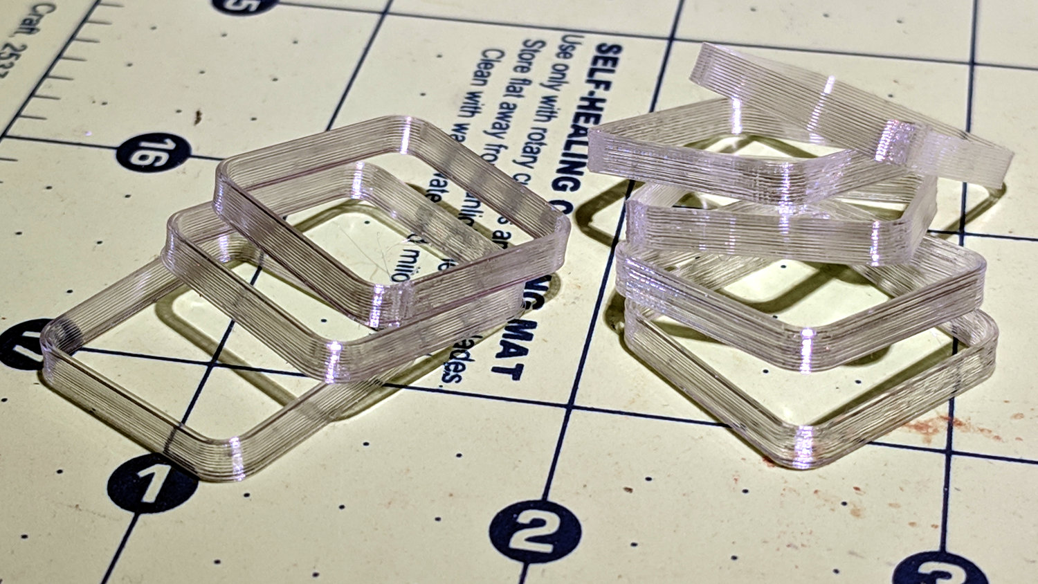
The bottom two squares in the left pile have squished first layers. The rest look just fine:
M2 Z-Axis – switch offset calibration squares
The whole set-and-test process required about 45 minutes, most of which was spent waiting for the platform to reach 90 °C in the 14 °C Basement Laboratory.
Aaand this front-end loader will require more than the patch kit and CO2 inflator from my bike pack before it’s back in service:
Front-end loader with flat tire
The local yellow iron inventory spends most of the winter snoozing in shopping mall parking lots, waiting to clear the snowfall. It’s been a light year so far, which is fine with me.