Ed Nisley's Blog: Shop notes, electronics, firmware, machinery, 3D printing, laser cuttery, and curiosities. Contents: 100% human thinking, 0% AI slop.
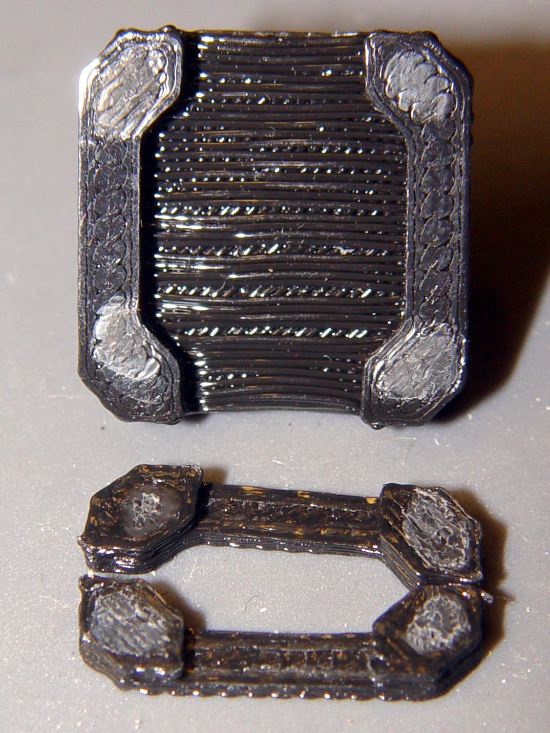
Fortunately, the link fell off in the box and I recovered all the pieces for a failure analysis:
Chain Mail Armor – failed link – glue spots
I’d glued the PLA together with IPS #4, a hellish mixture of plastic solvents including methylene chloride, one of the few chemicals able to chew into PLA, but there’s not much penetration or bonding going on.
Let’s try that again with a bit more solvent.
First, slide the bars into place:
Chain Mail Armor – failed link – bars in place
I applied four solvent drops in two passes to give it time to work its way in, put four matching drops on the armor cap, squished the cap in place, tweaked the bar alignment, then applied pressure while contemplating the whichness of the why for half a minute while the solvent worked its magic.
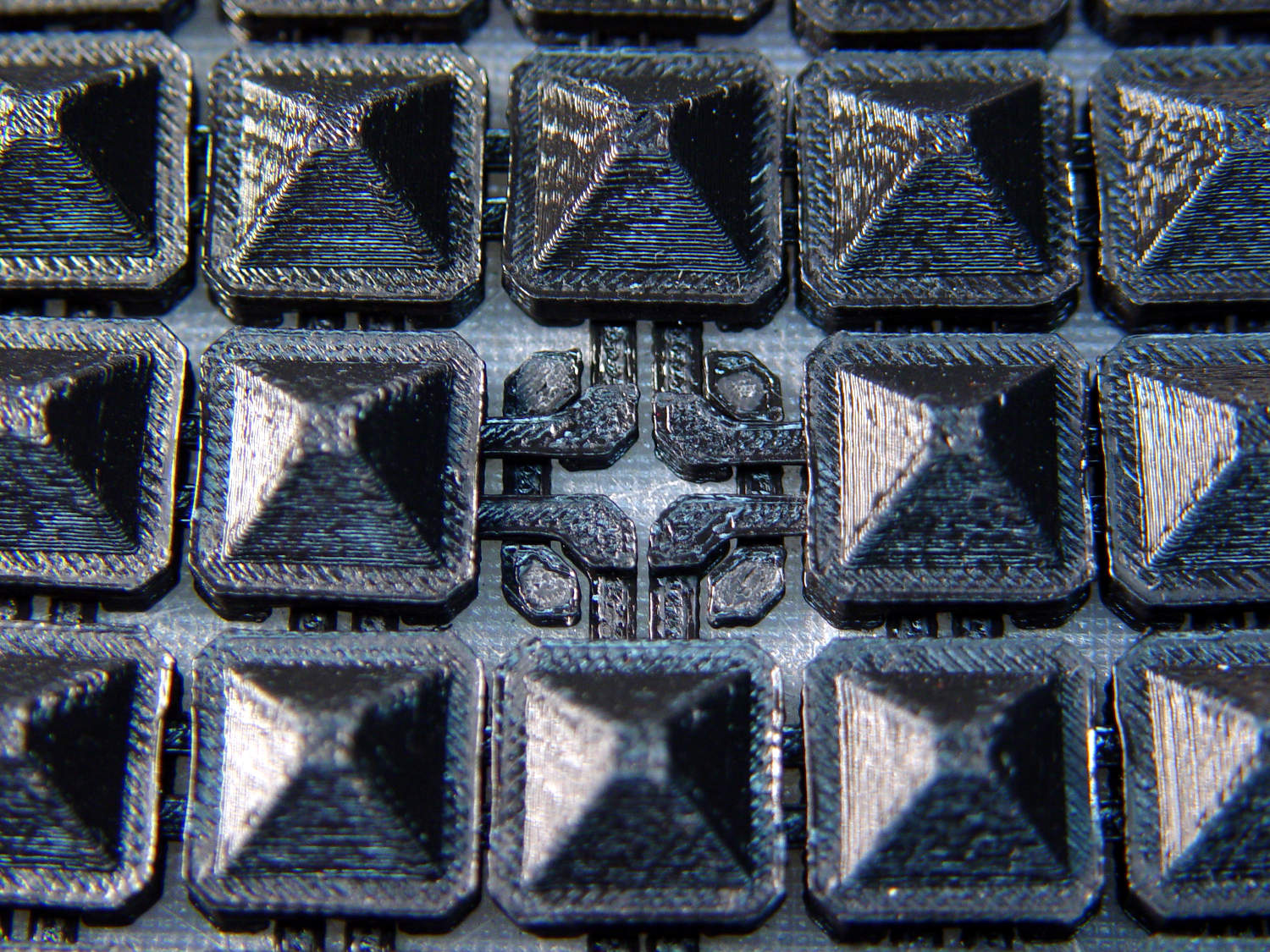
Things look pretty good once more:
Chain Mail Armor – missing link – repaired
There’s no way to determine the repair’s goodness, other than by deliberately trying to snap off a bar, so I’ll just put it back in the box and hope for the best.
Hydrant valves attach directly to the water main, far below the frost line, which means the hydrant itself should be dry when it’s not in use; the ice reveals a nasty valve leak. The corroded paint suggests a longstanding leak, but I admit to not noticing anything before now.
I uploaded the picture so I could include the URL in an email to the local fire department. I’ll take a look the next time we walk by to see what’s happened.
It’s been running more-or-less continuously since late 2016, so call it
Because I’d be crazy to replace it with another likely-to-fail WS2812, I had to remove both of them before installing SK6812 RGBW LEDs and updating the Arduino Nano.
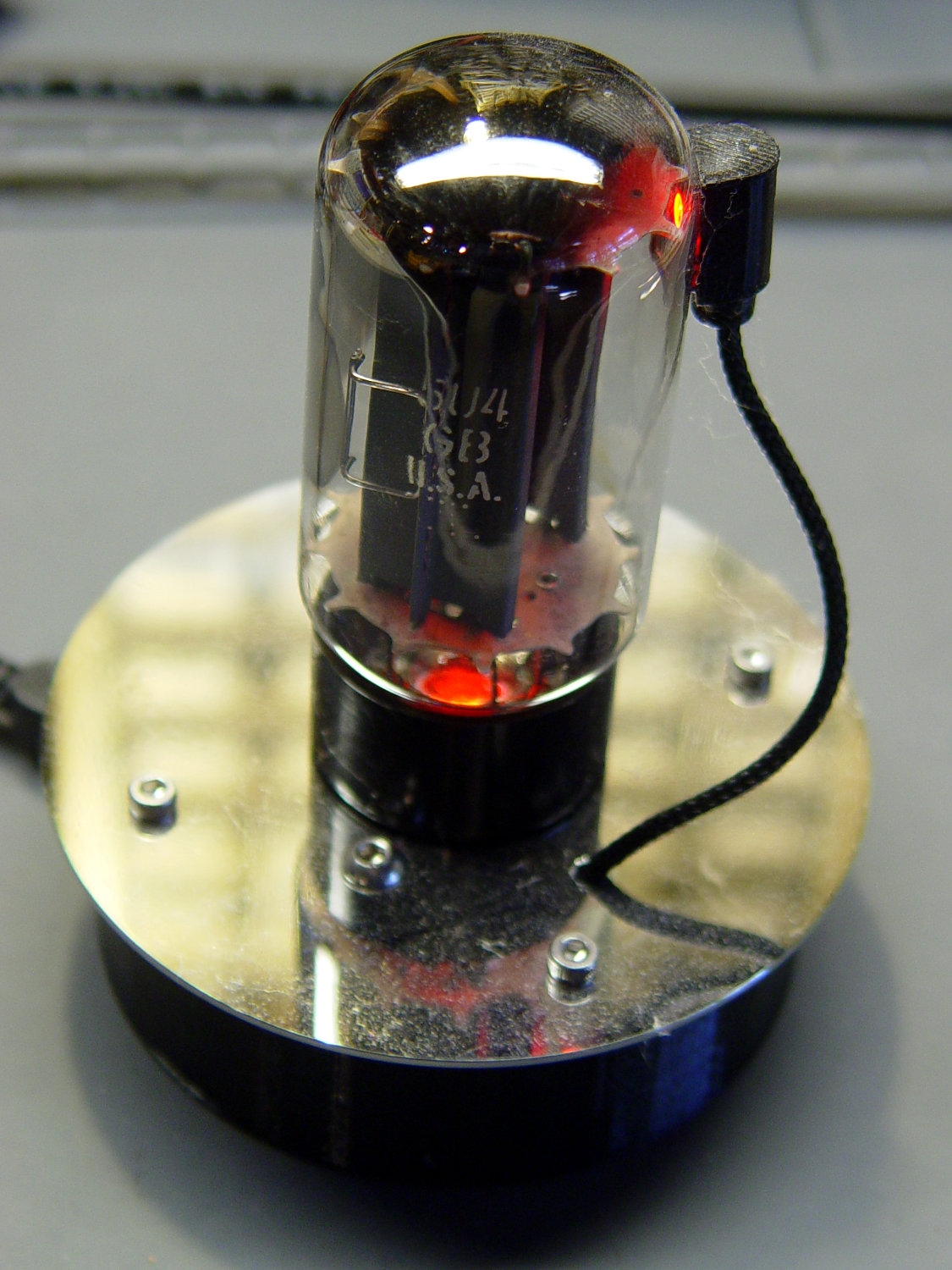
Unfortunately, I did a really good job of bonding the side light to the tube with epoxy:
Failed WS2812 – 5U4GB broken glass
The last tube manufacturing step involved flashing the getter onto the tube envelope, so as to remove the last vestige of air. Admitting air oxidizes the getter:
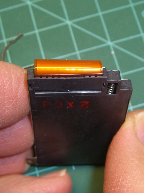
Gently pry the metal cover outward to clear the latches along the sides:
DSC-F717 – Memory Stick socket cover latches
The cover remains held in place by two tabs inside the holes on either side of the Memory Stick contacts, one of which is already free in the previous photo:
DSC-F717 – Memory Stick socket – bottom
The small spring on the left ejects the Memory Stick and will, if suitably provoked, launch itself across the bench. Be prepared!
Use a pointy instrument to ease those tabs away from their latches and pop the top:
DSC-F717 – opened Memory Stick socket
I cleaned the contacts, not that they appeared particularly filthy, gently bent them upward by three micro-smidgens to apply a bit more pressure to the card’s contacts, and reassembled the socket in reverse order.
I put a strip of Kapton tape on the back of the cable termination paddle (shown here during the previous repair) to ensure a snug fit:
DSC-F717 Memory Stick socket – cable entry
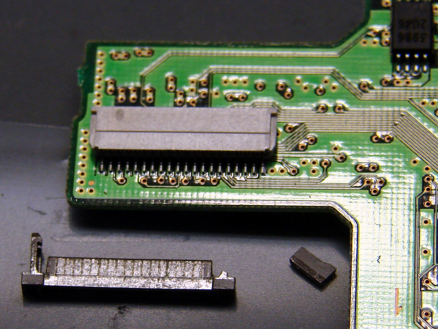
Unfortunately, I snapped off a locking tab on one of the ribbon cable connections to the main board:
DSC-F717 – broken cable clamp
The cable threads through the middle of the clamp, which then slides into the socket and applies pressure to the contacts through the cable: no clamp, no pressure, no good.
For lack of anything smarter, I tamped the clamp into the socket and applied a strip of Kapton tape to maintain everything in more-or-less the right position:
DSC-F717 – tape-anchored cable
Definitely unpretty, but better than nothing. While I was in there, I reinforced the other connections with similar clamps.
Reassemble the camera in reverse order and it’s all good:
DSC-F717 – repaired – first image
It probably won’t last another decade, but ya never know …
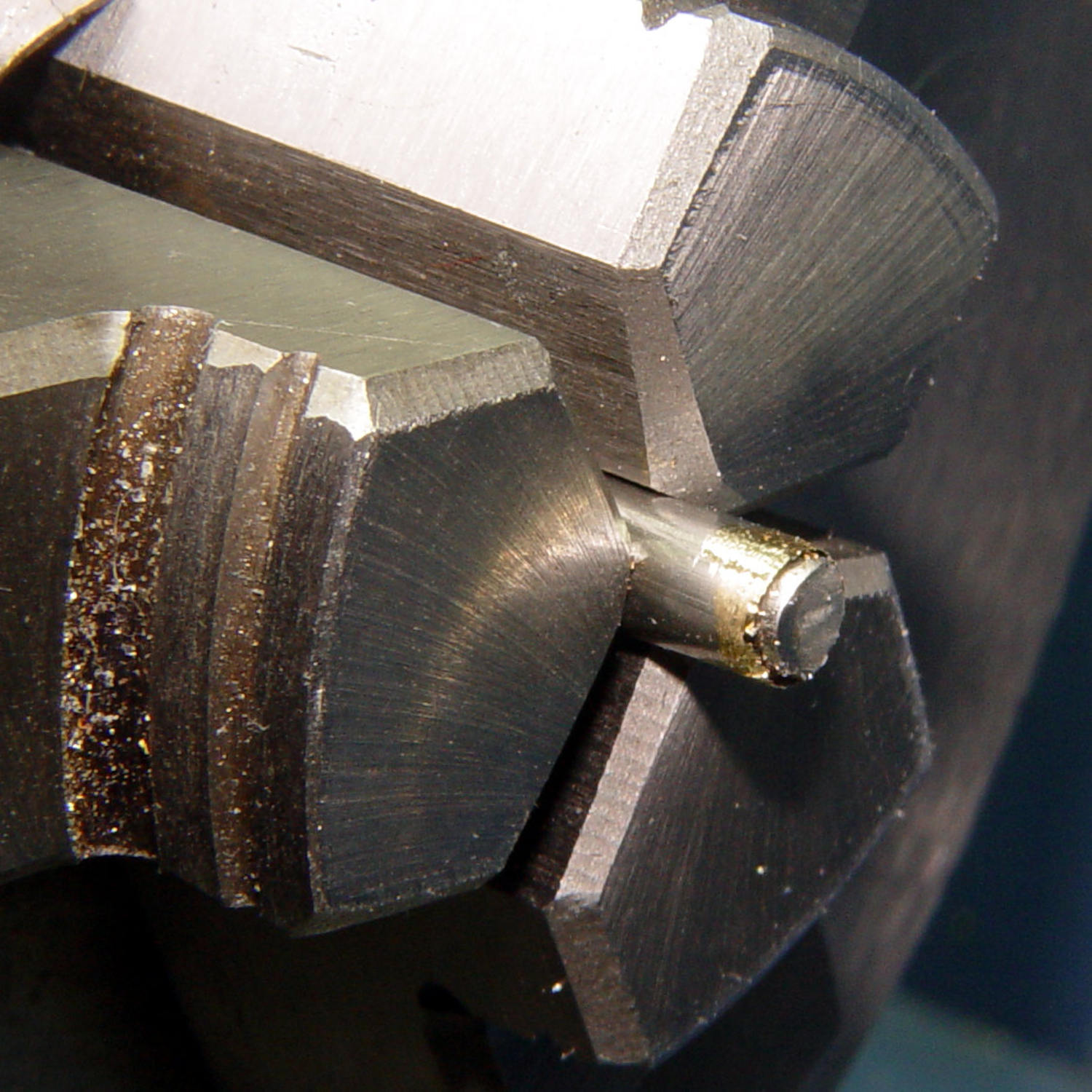
After considerable evaluation, the Customer decided the shoelaces were still too long and said the hex-crimped ferrules were entirely too rough and tended to snag on things. This time, I prepared the ferrules by chucking them in the lathe:
Ferrule – original flange
The steel rod inside the ferrule encourages it to remain round and not collapse while I’m filing off the flange that normally holds the plastic strain-relief doodad:
Ferrule – reshaped flange
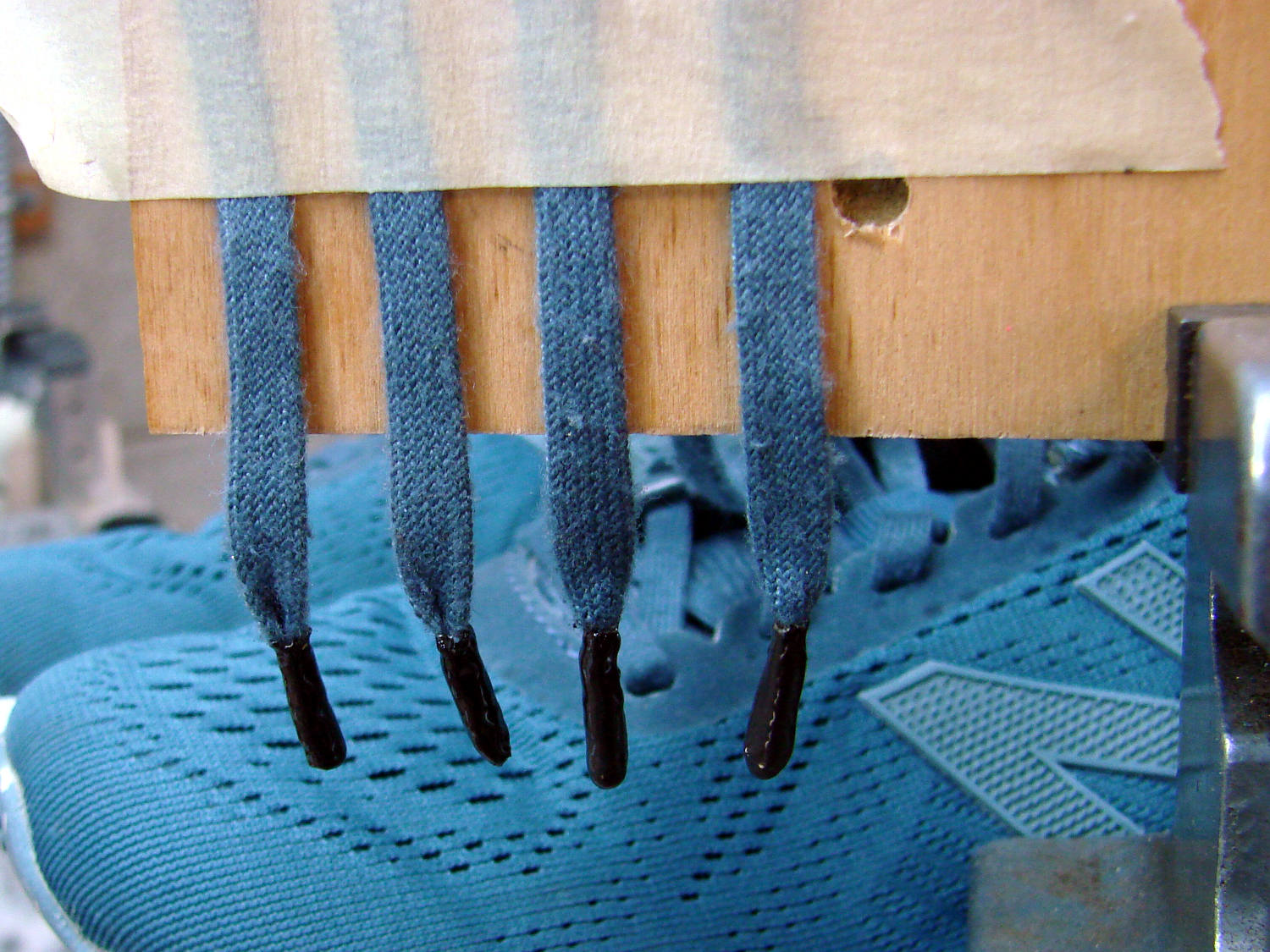
I snipped another half inch off each end of the laces and crimped on the prepared ferrules:
Shoelace ferrule aglets
Which were definitely too jaggy, so they now sport an epoxy coat:
Ferrule aglets – epoxy coat
Alas, JB Kwik epoxy has a pot life measured in minutes, so the last ferrule looks a bit lumpy. They seem to work fine and the Customer is happy with the results.
Memo to Self: Next time, dunk the ferrules in a pot of slow-curing JB Weld and let them drain overnight.
the random up and down movement doesnt make any sense
It’s what happens when a stepper is mechanically overloaded: the rotor can’t turn at the commanded rate.
Start by cleaning & lubing the Z axis guide rods and leadscrew. If that solves the problem, just clean and lube a bit more often. Which none of us do until there’s a problem, of course. [sigh]
If it continues to stall, reduce the Z axis speed by a factor of four. If that solves the problem, then perhaps you tweaked the speed while you were fixing other problems and never noticed.
the technical reason why the motor would move in the opposite direction
The windings set up a rotating magnetic field which, in normal operation, drags the rotor around with it. When the rotor stalls, it vibrates back-and-forth and may wind up synchronizing with the field in the wrong direction.
Old Western movies had a similar problem with wagon wheels turning faster than the frame rate and looking like their spokes rotated backwards.
The stepper may emit horrible sounds, but stalling doesn’t do any damage to the motor or its driver.
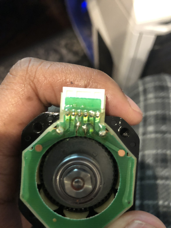
I took the bottom of the motor apart
No sugarcoating: disassembling a stepper demagnetizes the rotor. You must buy a new Z-axis motor.
The motor is assembled with the rotor demagnetized, then it’s magnetized in place. When you take it apart, the rotor smacks into the stator, which creates a localized high-density magnetic path between the rotor poles. The rotor poles can’t support the high flux and demagnetizes.
You can put the motor together and it will “work”, in the sense that the rotor will go around, but the decreased magnetic field reduces the torque for a given winding current. You can’t increase the winding current, because the motor will overheat.
The PCB traces look mangled and warped
There’s a conformal coating over the whole PCB to prevent corrosion, so what you see is perfectly normal.
Any analysis of the data from my previous posts?
You’ve been doing a lot of fiddling with the machinery as part of finding the extruder problem, so: did you, at any time, even once, unplug / disconnect the Z axis motor when the power was turned on?
If so, that likely killed a driver transistor in that channel. Order a new RAMBo board along with the new motor.
New Rambo board came today and the z axis is working properly now.
Moral of the story: never fiddle with the electronics with the power turned on!
As soon as my z endstop triggers, the firmware resets
The Z endstop cable is plugged backwards into the RAMBo socket.
The RAMBo socket has three pins: [+ – S].
The two-wire switch cable ends in a three pin connector shell (*) with one empty contact. Unfortunately, the cable connector is not symmetric, not keyed to fit the socket latch, and easily fits into the RAMBo socket either way.
Plugged correctly, the two switch wires go to the [- S] socket pins, putting the [+] socket pin in the empty contact.
If the cable is plugged backwards, the two switch wires go to the [+ -] pins, putting the [S] pin in the empty contact.
Plugged backwards, when the switch trips, it shorts the power supply to ground. Unpleasant consequences ensue.
(*) I’d be unsurprised to discover a machine with a two-wire switch cable ending in a two-pin connector shell. Those must plug into the [- S] pins, leaving the [+] pin waving in the breeze.