Mashing the LED PCB into place didn’t entirely solve the weak beam problem, so I unscrewed the tailcap holding the switch on the other end of the body:
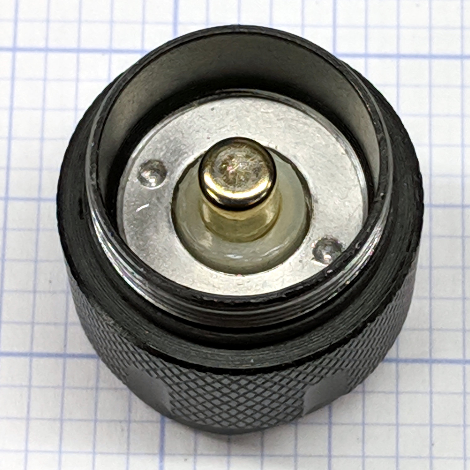
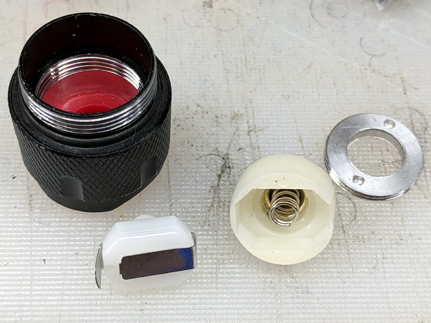
Unscrewing the lock ring releases the switch assembly:

I suspect the tab sticking out from the side of the switch doesn’t make / never made good contact with the aluminum tailcap body, but having gone this far there’s no reason to stop. The plastic housing around the spring-loaded brass battery contact pops off to reveal the actual switch:
The long tab on the front of the switch sits under the spring, so that’s the negative battery contact. The LED current goes through:
- battery negative to contact + spring
- switch tab + moving contact + tab
- tab to tailcap pressure fit
- tailcap threads
- front tube threads
- LED pill to PCB
- spring to battery positive
So. Many. Aluminum. Joints.
The switch body snaps apart to disgorge a remarkable number of parts:
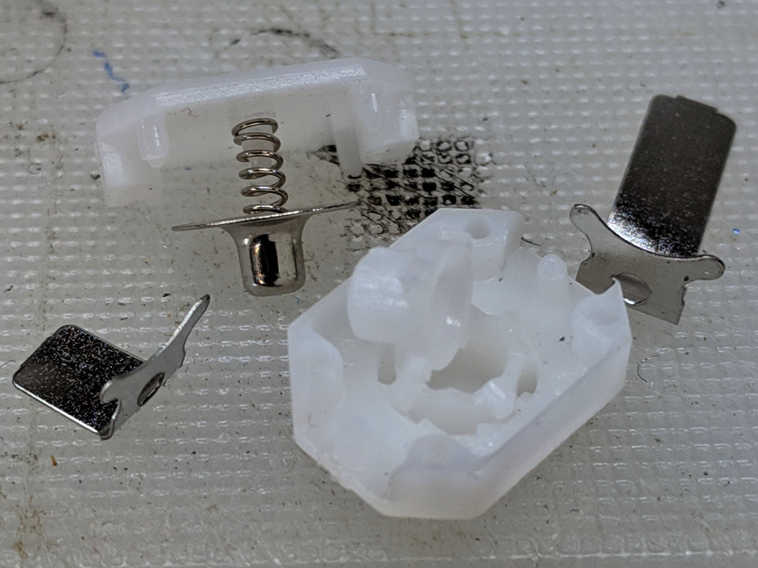
Nothing looked out of order, so I applied a thin layer of DeoxIT Red to all the contacting parts and reassembled everything.
For the record, the switch’s internal parts have many plausible assembly sequences; the workable one goes a little something like this:
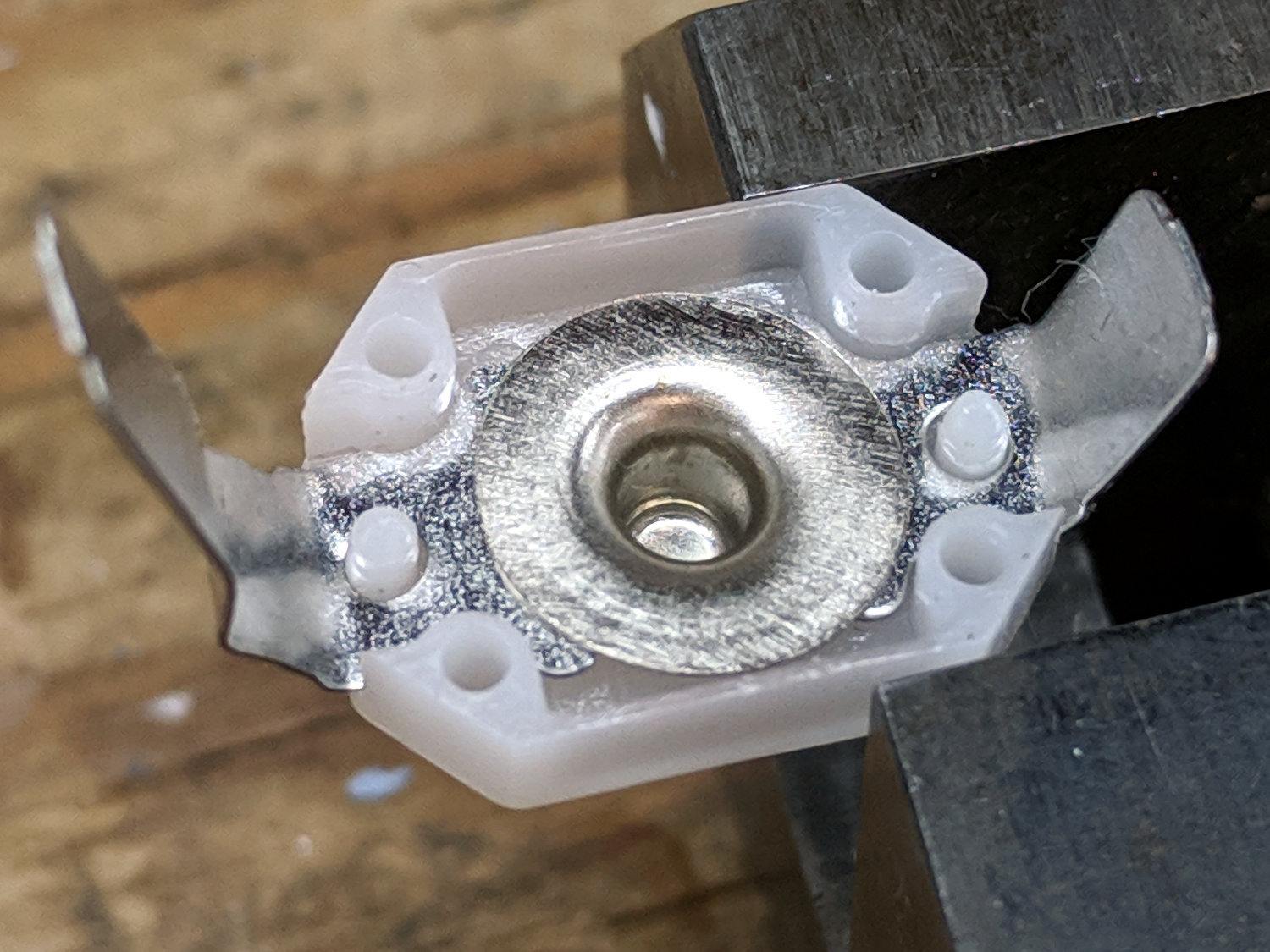
Contrary to what you (well, I) might think, the switch is off when the central contact is pushed forward, away from the side contacts.
I bent a slight angle into the tailcap contact (on the right in the picture) to make better / firmer contact with the tailcap body, cleaned all the threads with a cotton swab carrying a dab of DeoxIT, and screwed it all together.
With everything back together, the beam seems bright and steady again. We’ll see how long it lasts.
