Ed Nisley's Blog: Shop notes, electronics, firmware, machinery, 3D printing, laser cuttery, and curiosities. Contents: 100% human thinking, 0% AI slop.
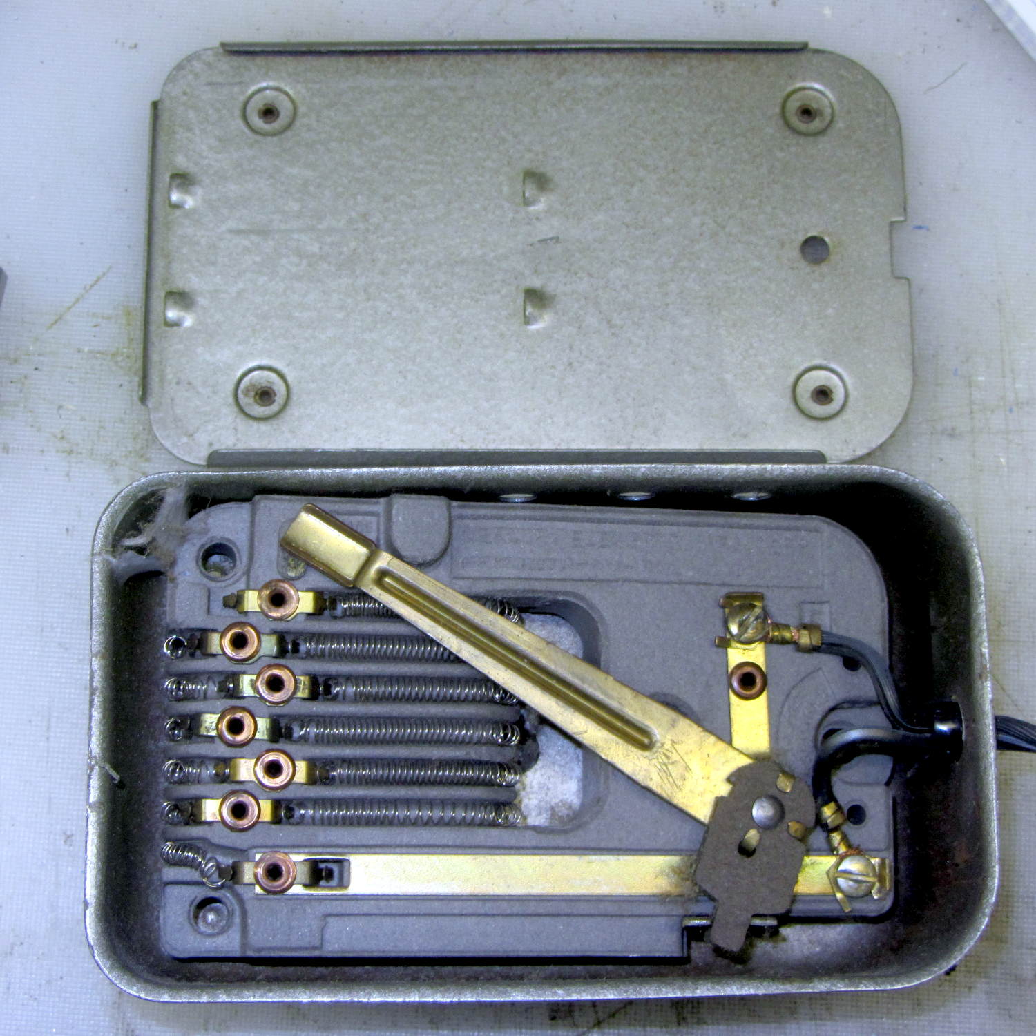
Based on the paperwork tucked into the sewing table, the most recent Kenmore Model 158 sewing machine in our stable dates to 1972, a bit earlier than the others, and has a metal-cased foot pedal with a wire-wound resistor:
Kenmore Model 158 – new-ish foot pedal resistor
The cord insulation stiffened up over the decades and I wanted to replace it, but the contacts in the sewing machine connector were spot-welded to the conductors with no room for teeny screws:
Kenmore Model 158 – new-ish foot pedal connector
I blew out the fuzz, put it back together, and it works pretty well, modulo the usual low torque at slow speeds issue.
The discrete resistor taps produce a somewhat stepped response, but early reports suggest it’s not enough to be annoying; it’s much more stable than the carbon disks in the more recent pedals.
The weakest fluorescent shop light fixtures always fail during cold weather (apart from the usual early tube failures) and this winter’s cold spells triggered the usual carnage, so I picked up half a dozen (cheap) 22 W LED T8 tubes and set about rewiring three defunct (cheap) fluorescent fixtures from the recycle heap. The new LED tubes run directly from the AC line; you must remove the fluorescent fixture’s ballasts / capacitors / starters and rewire the “tombstone” lampholders accordingly.
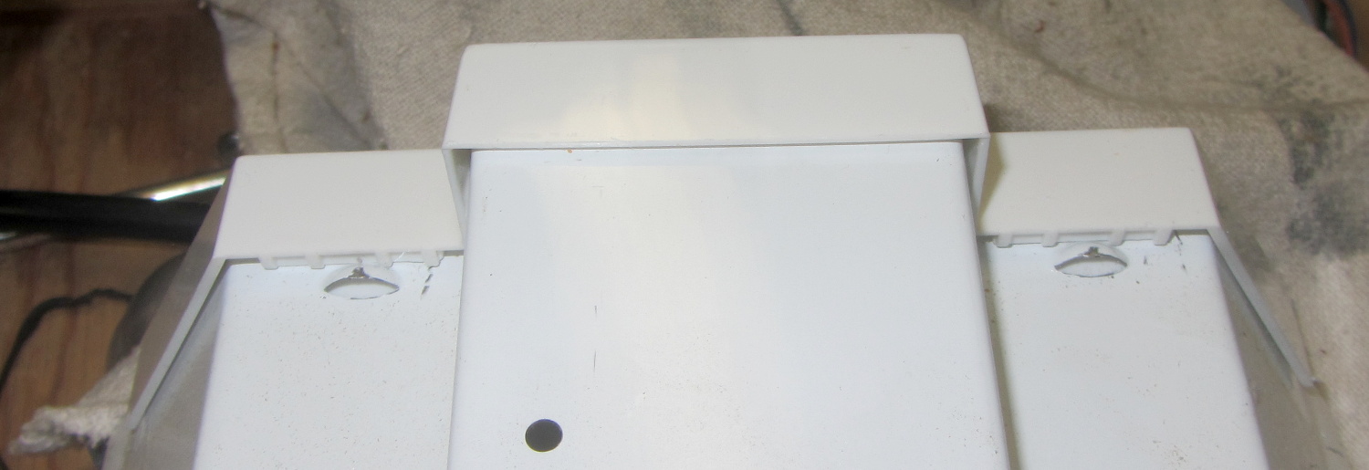
The first challenge, as always, involved taking the fixtures apart. Turns out prying the endcap away from the fixture enough to clear the pair of bumps punched into the metal does the trick:
Fluorescent Shoplights – endcap latches
Each endcap contains the ballast inductor / choke and power-factor correction capacitor for one tube. The inductors from one shoplight had a fancy plastic tab that might have held the capacitor in place, but that’s about the only difference:
Fluorescent Shoplights – ballasts
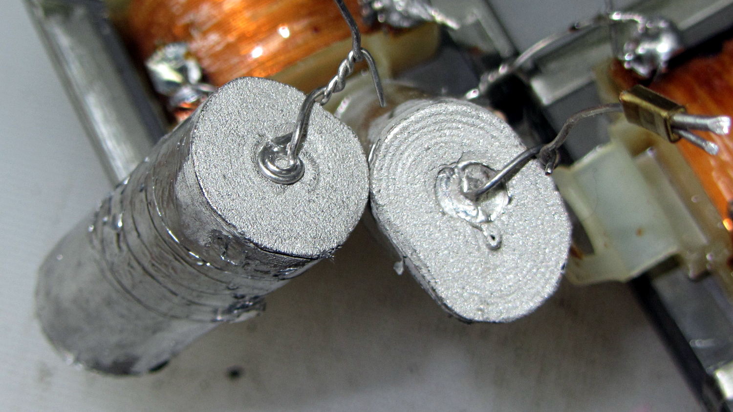
The 150 kΩ resistor has its leads twisted around the capacitor leads without benefit of that fancy solder stuff one might think necessary for a good connection.
The capacitor contacts use the minimum possible amount of material:
Fluorescent Shoplights – capacitor termination
I think the caps use metallized Mylar film, but who knows?
The inductors measure 280 mH and the caps a whopping 5 µF. I might trust the inductors in a low-voltage circuit, but the caps have no redeeming features and went directly to the trash.
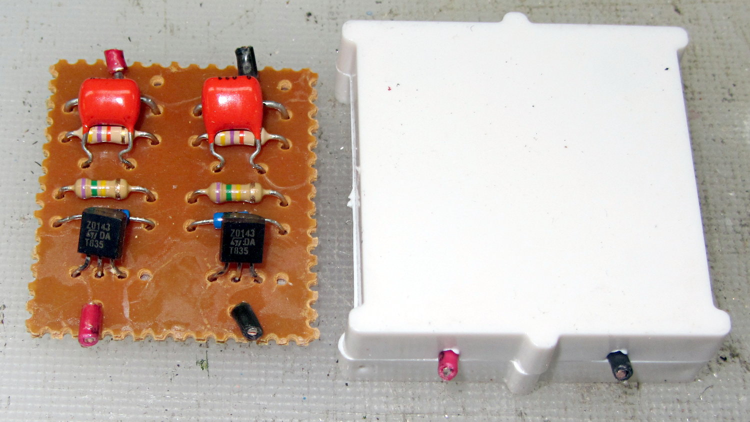
The starter PCB lived in the center of the fixture:
Fluorescent Shoplights – starter circuit
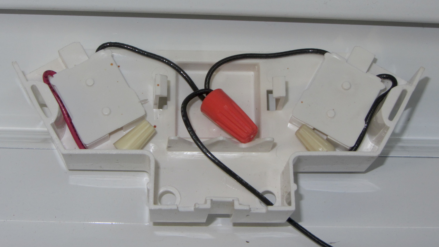
I deliberately picked LED tubes with the AC line contact on one end and the neutral contact on the other, so as to not put line and neutral contacts in the same tombstone. After rewiring, the neutral endcap looks like this:
Fluorescent Shoplights – neutral endcap
The other endcap holds the power cord and has a green earth ground wire snaking out to a little tab passed into a slot punched in the metal case. I replaced the tab with an actual screw / solderless connector / toothed washer, but have no pix to show for it.
The LED tubes run at 6500 K and contrast harshly with the warm-white tubes in the fluorescent shoplights. I went with the highest light output, because even the best (cheap) LED tubes produce barely half the output of the fluorescents: 2000-ish lumens vs 3900-ish.
For reasons that should not require explanation by now, Mary just acquired a large sewing table (along with a Sears Kenmore Model 158 sewing machine that’s slightly older and fancier than the three we already have). The table has an opening fitted to the machine base, but the rubber pads atop the leveling screws had long since stiffened up and two screws were frozen in place. A few drops of penetrating oil released the screws and, mirable dictu, they have ordinary 6-32 threads.
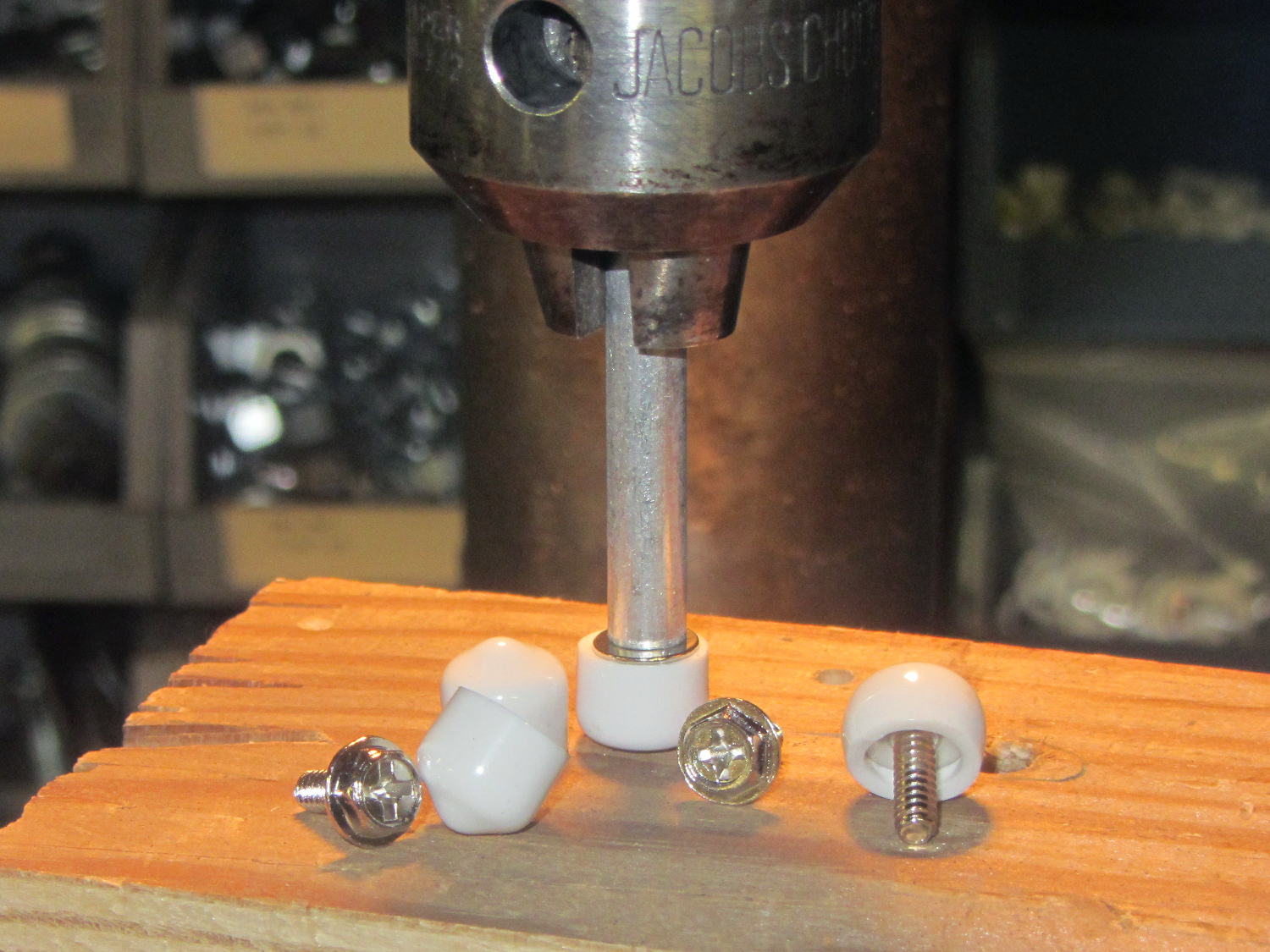
Some rummaging turned up four PC case screws and soft caps intended for wire shelves, which easily combined into replacement machine supports:
Sewing Machine Supports – inserting screws
Once again, I’m using the drill press as a low-force arbor press, with a chunk of aluminum tubing to shove the screw flange into the slightly smaller plastic cap.
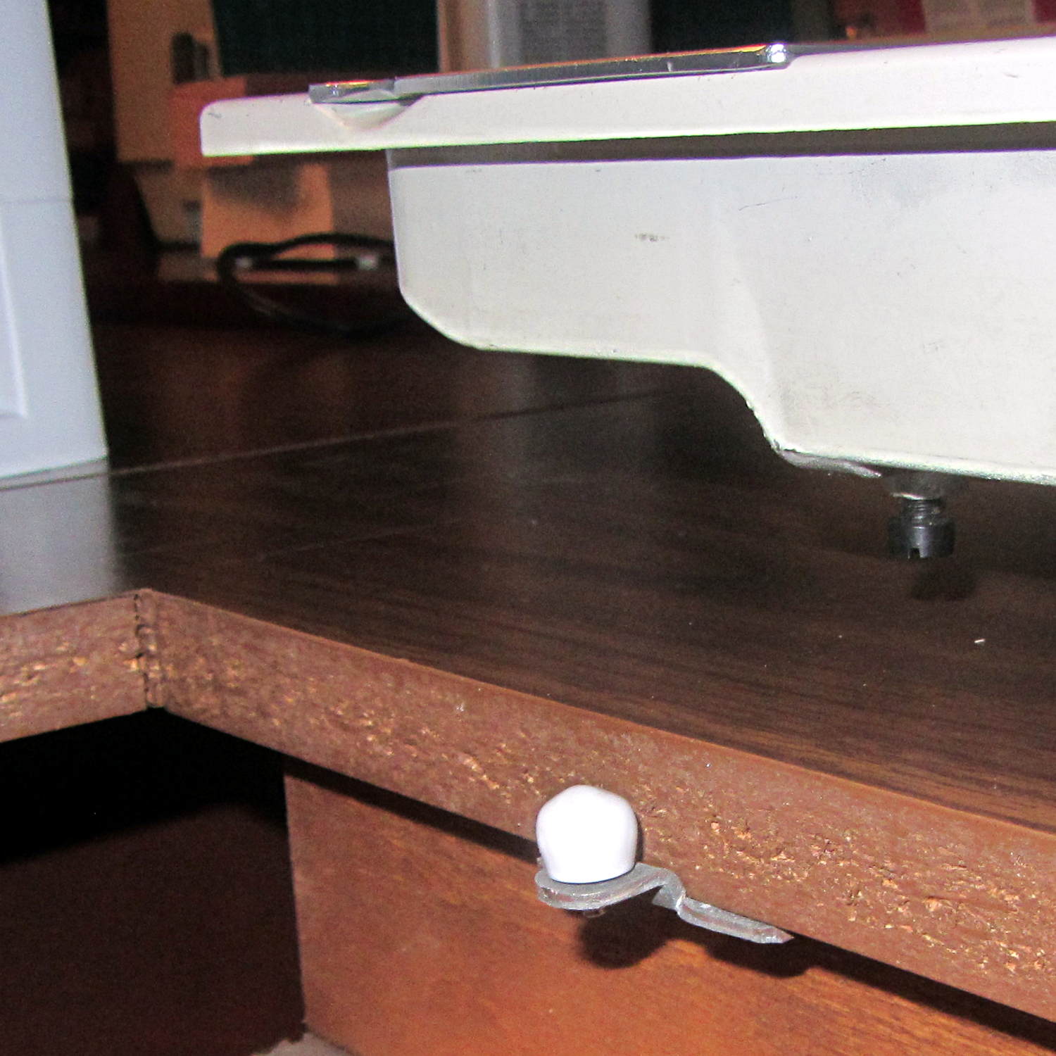
Spun into their brackets, they look quite nice, not that anybody will ever see them:
Sewing Machine Supports – installed
The new-to-us table replaces the incredible collection of junk previously supporting Machine #3. I tucked some plastic foam around the near and right edges to fill the small gaps and it fits well:
Sewing Machine Supports – machine installed
Obviously, the foam will fall out whenever Mary lifts the machine to tinker with machinery under the platform, so we’ll see how often pins & needles slip through the cracks without the foam.
The fourth Sony MicroSDXC card went into service in late September 2015 and has now failed after about 60 sessions in my Sony HDR-AS30 Action Camera. This one sported a U3 speed rating and I had hopes that would improve its longevity, but that doesn’t seem to be true.
The defunct Sony card (marked in red to avoid confusion) will join its defunct compadre and the Sandisk Extreme Pro card goes in the camera:
Sony 64 GB MicroSD SR-64UX – failure
The 16 bike rides in December added up to 220 GB; call it 13.75 GB/trip. January 2016 shows only three rides and it failed after two February rides: barely 60 rides for a total of 825-ish GB of video data. The three previous Sony cards failed after less than 1 TB of data, putting this one in the same ballpark.
I have no way to measure the actual write speed, but the camera shuts down after recording less than a minute of 1920×1080 @ 60 f/s video. Previous cards worked fine at lower video resolutions and recording speeds; I’ll assume this one behaves similarly. It might make a capacious “disk” for a Raspberry Pi.
When the previous card failed, Sony’s “customer support” decided that there might be something wrong with the camera’s firmware causing it to trash the cards, so there was no point in replacing the card under warranty and I should send the camera in for a checkup. When I pointed out that they’d strung me along for a year, until the camera was out of warranty, without mentioning even the possibility that the camera might be at fault and asked whether they’d pick up the $100+ bill for having the camera “examined”, the Nice Man said Level 2 would get back to me after “48 working hours”. When prodded, he agreed that “48 working hours” equaled “6 working days” and didn’t include weekends; when we had that settled, I knew they had no further interest in this matter.
Sony hasn’t called back and, by now, I don’t expect they ever will. It’s not worth my time to pursue this any further, but if you’re wondering how well Sony MicroSD cards work in Sony cameras and how well they support the failures, now you know.
So, starting with this riding season, we’ll see how long a Sandisk Extreme Pro card survives…
So, while printing the first pass of the halogen lamp base, this happened:
Lamp Base – wrecked print
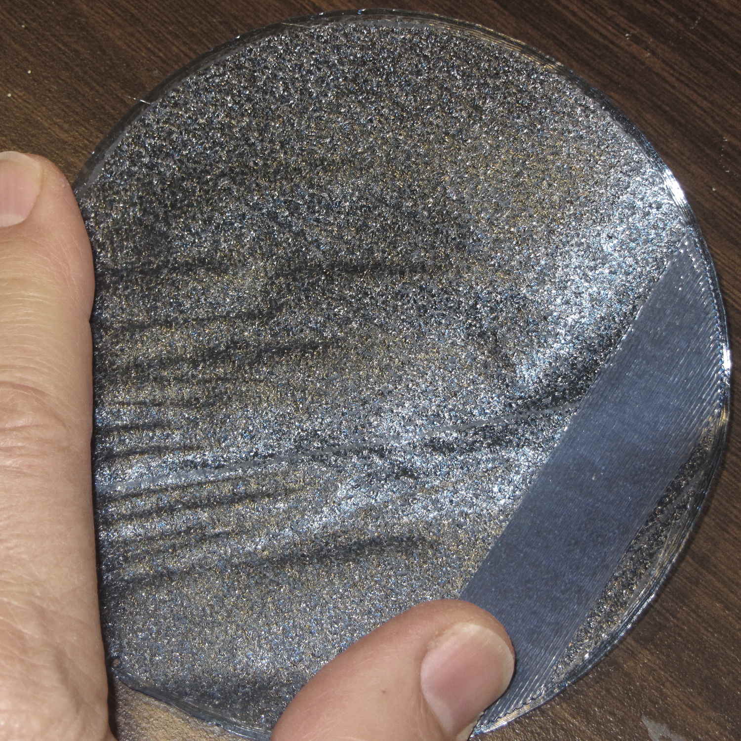
The first layer went down fine, but the filament stopped feeding after laying down the small linear patch along the right side. The wrinkles come from me peeling it off the platform while it was still hot and flexy.
Although feeding PETG at 75 mm/s for infill worked so far (I mean, sheesh, look at all the stuff I’ve made in the last year), this involved a fairly large expanse of filament and maybe, just maybe, the high flow rate cooled the nozzle enough to increase the extrusion pressure and eventually strip the filament.
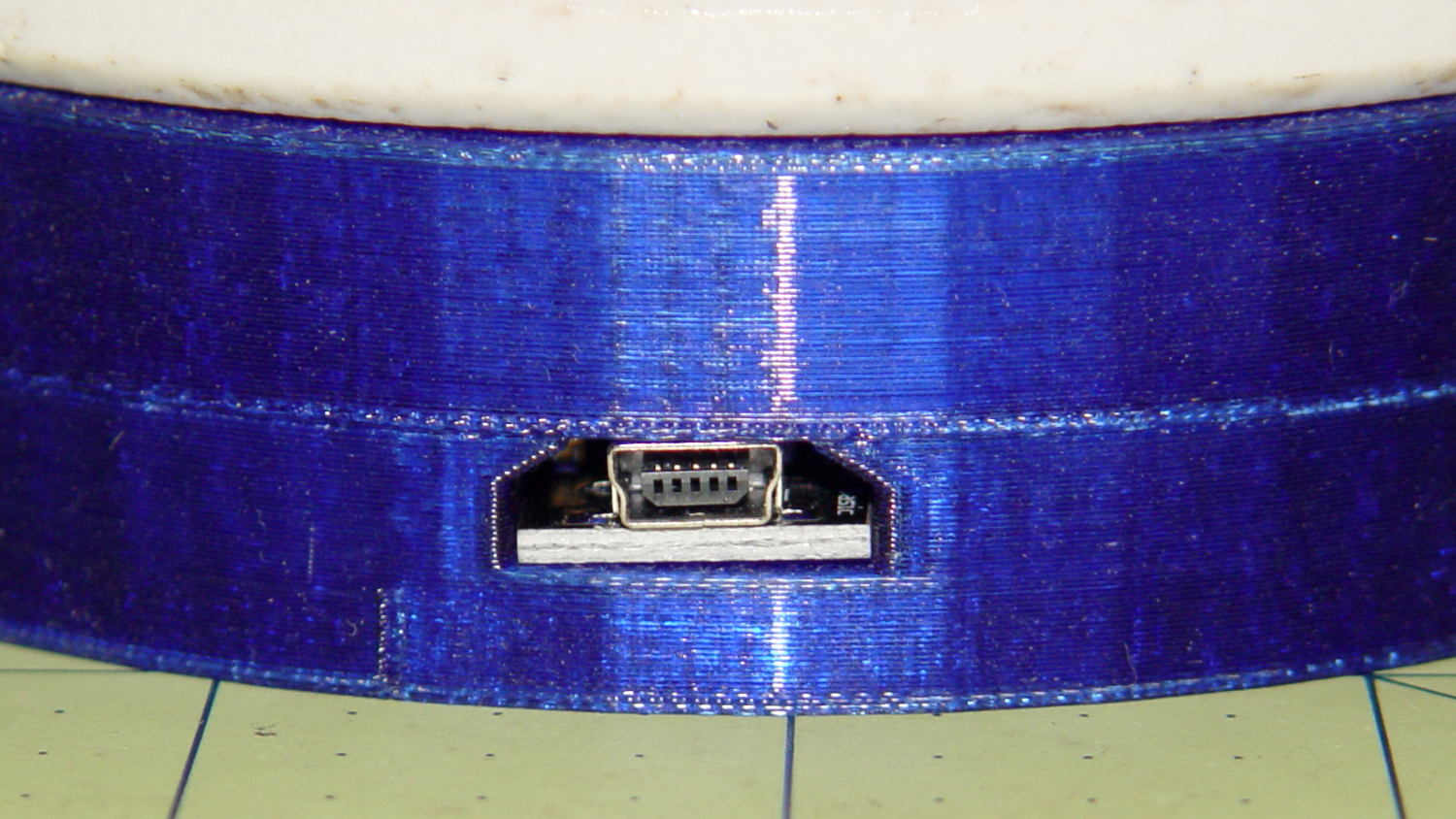
I shoved the filament hard enough to get it feeding again, bumped the extrusion temperature to 260 °C and started another print, whereupon things went swimmingly for the first 12.2 mm. Alas, the filament jammed again, just below the top of the hole for the USB adapter, where you see the odd line in the middle of the finished base:
Lamp Base – USB port
Because it’s now printing a relatively thin cylinder at relatively slow speeds (less infill per perimeter), the “feeding too fast” argument falls flat on its face: obviously, something else is wrong.
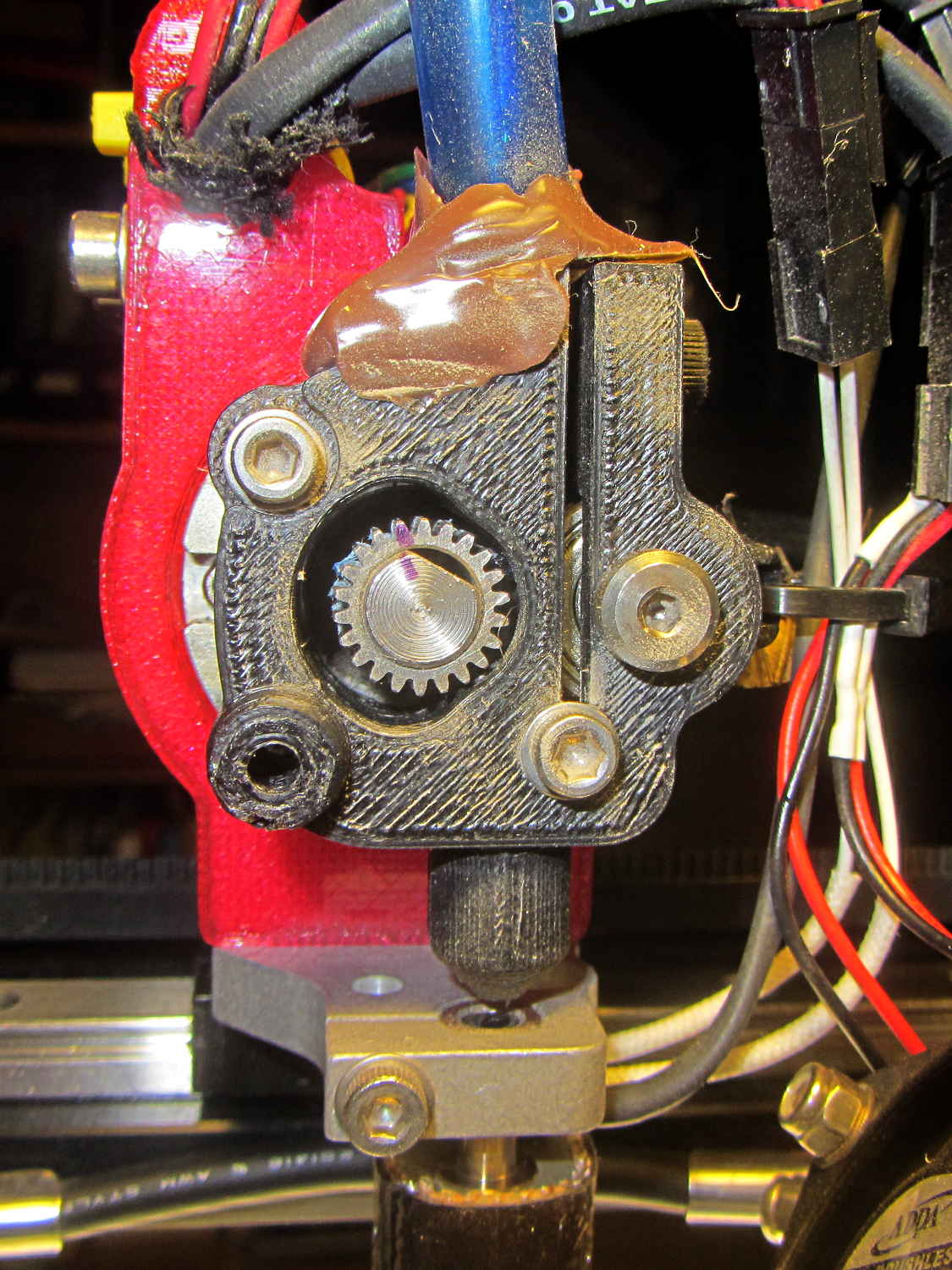
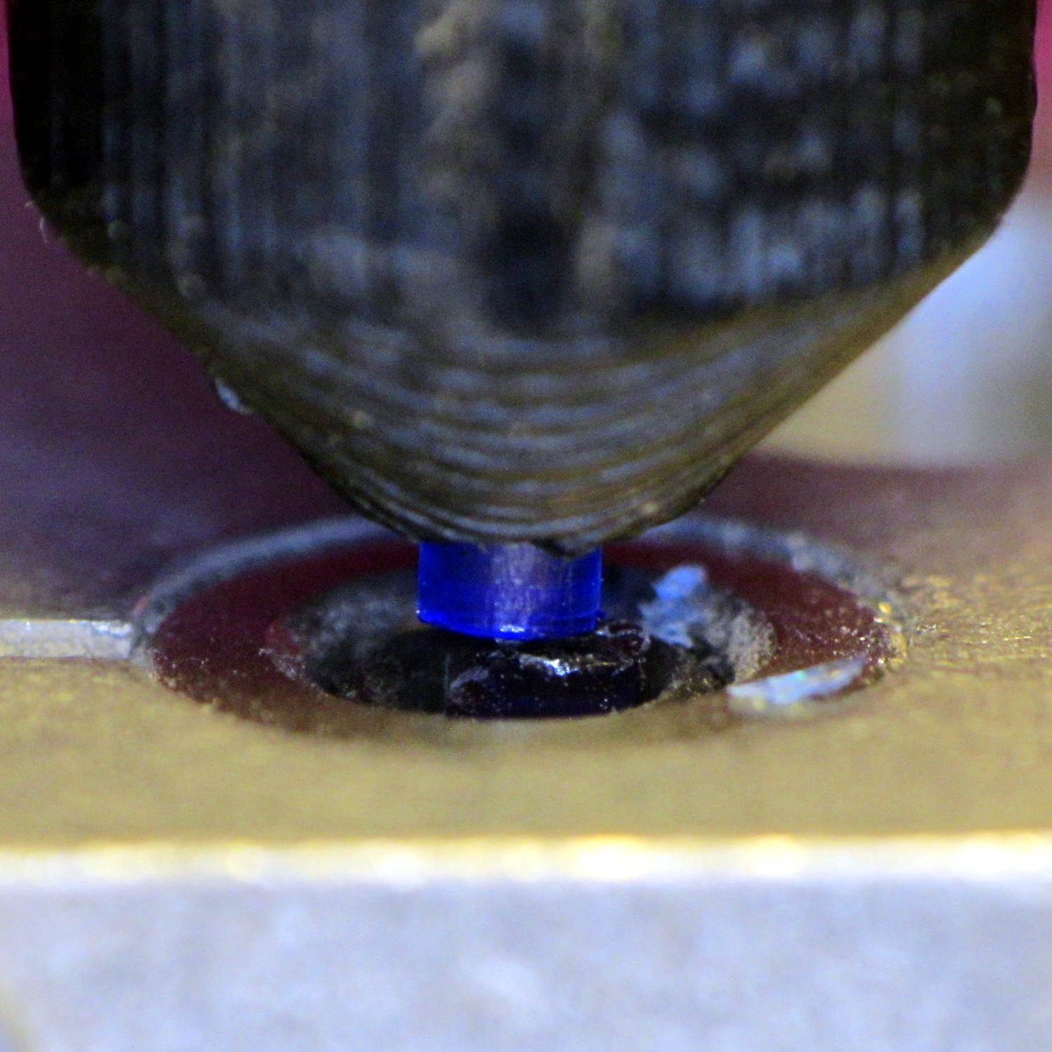
Removing the fans showed a bit of plastic on the drive gear teeth, but nothing too terrible:
M2 Filament Drive – jam front view
The witness mark on the planetary gearbox output shaft still lines up with the mark on the gear, so the tiny grub screw hasn’t come loose. Note the slight misalignment between the bottom of the filament drive and the hot end inlet; I’ve already snipped the filament and done some retraction.
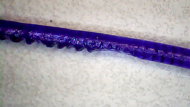
A small struggle involving needle nose pliers dragged this classic gouged filament from the drive:
Stripped PETG Filament
This spool of PETG filament started out at 1.70 mm, but this section measures 1.80 mm. That’s at the high end of the ±0.05 mm tolerance around the nominal 1.75 mm, but, frankly, I don’t take the tolerance too seriously.
Undamaged filament from the spool didn’t push smoothly through the drive, so I reamed out the entire path with a 2 mm drill (actually, a #46 drill = 2.05 mm). I don’t recall if I did that before mounting the drive, but even if I did, I’d expect some crud and distortion to accumulate after a while; it’s been running without much attention since last March.
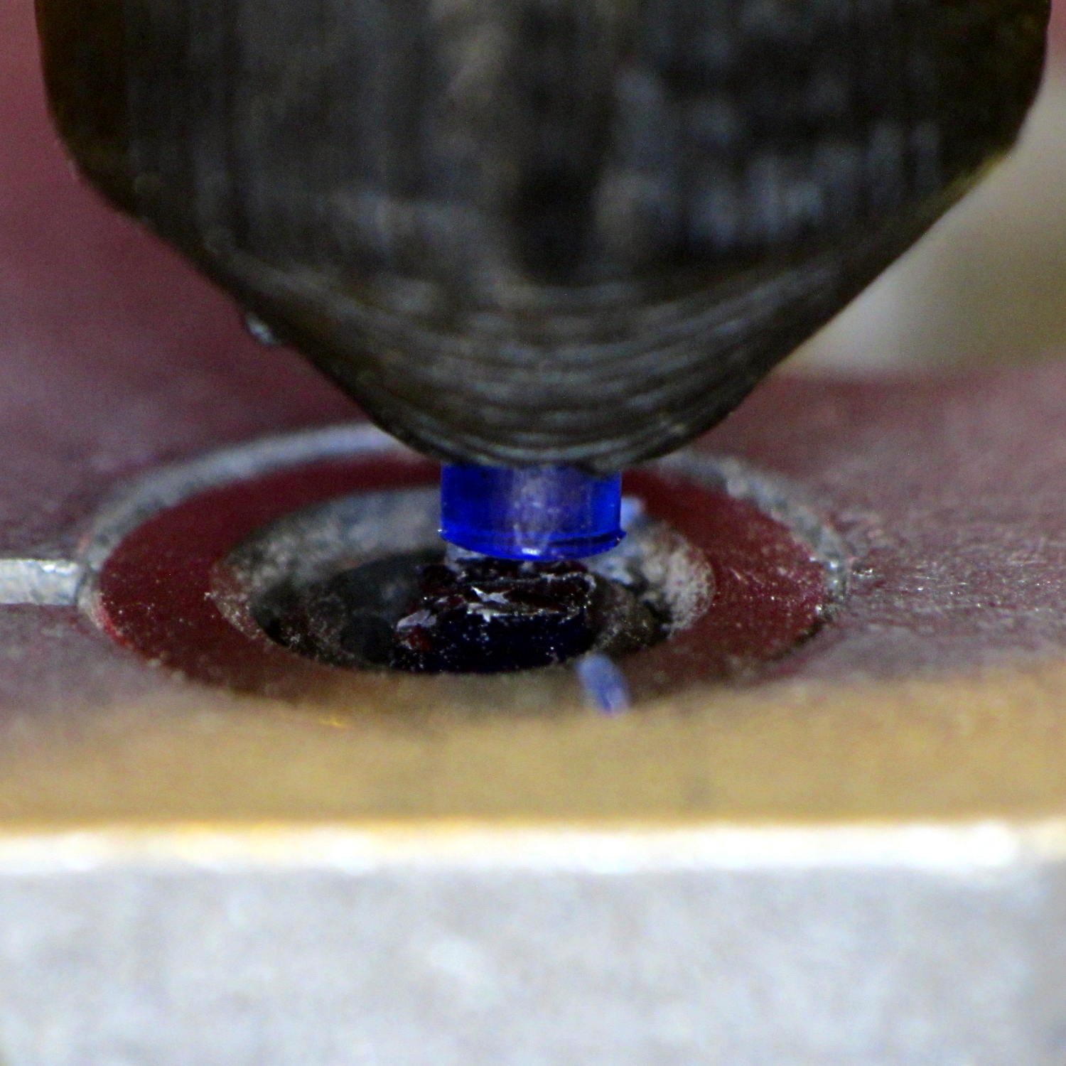
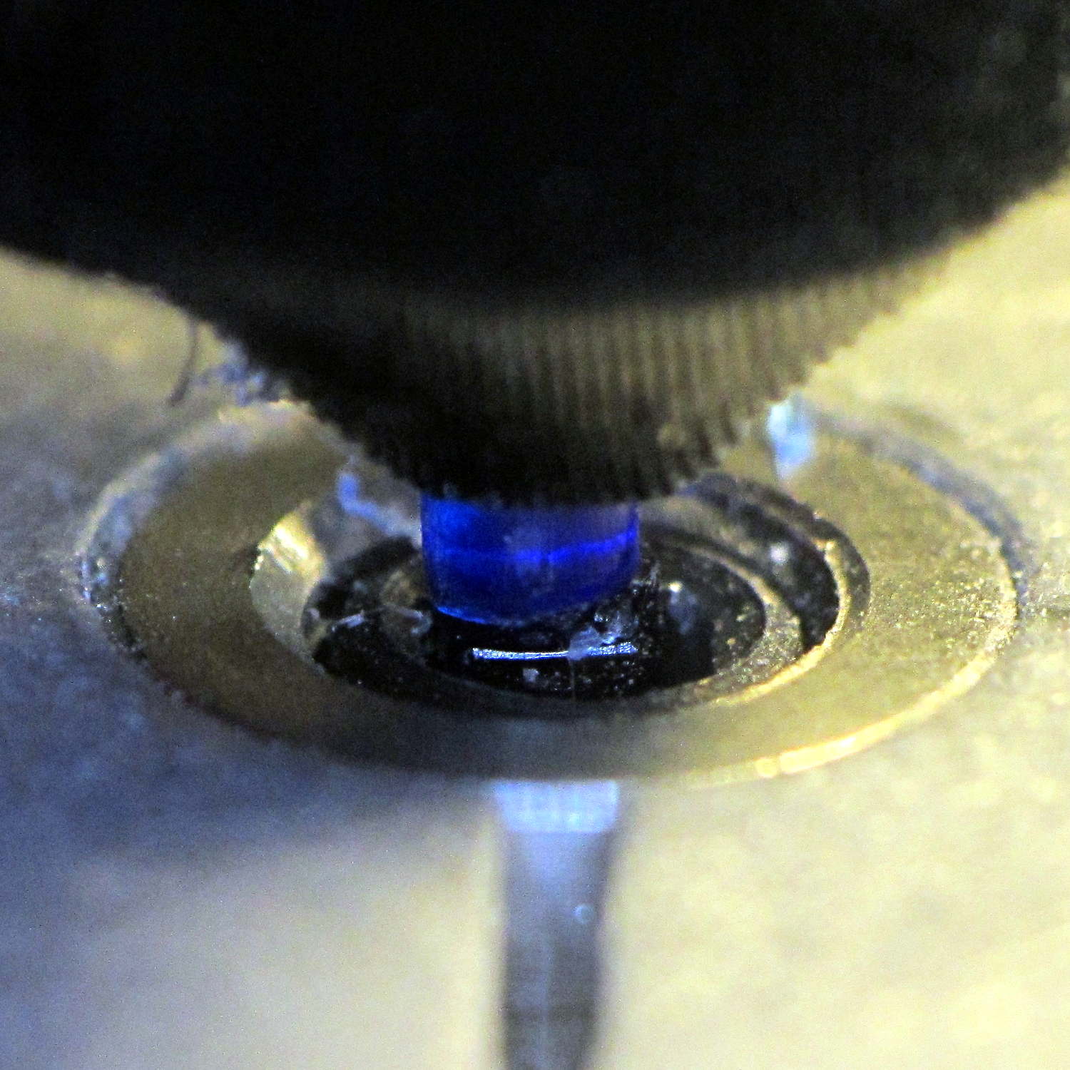
Reassembling the drive and feeding the filament to just above the hot end showed a slight misalignment:
M2 Filament Dive – misaligned front view
I cured that by loosening the screws and rotating the whole drive slightly clockwise:
M2 Filament Dive – realigned front view
Viewed from the side, the drive positions the filament slightly too far to the rear:
M2 Filament Dive – alignment side view
I didn’t (think to) check if the hole in the snout has become bellmouthed, but it wouldn’t take much. In any event, the filament fed into the hot end without incident, so maybe there’s enough slop to cover that misalignment. Maybe I should add a small shim behind the drive?
With the filament drive working again, I had Slic3r chop the bottom off the solid model of the lamp base and create the G-Code for just the top section, which printed without any problem at all.
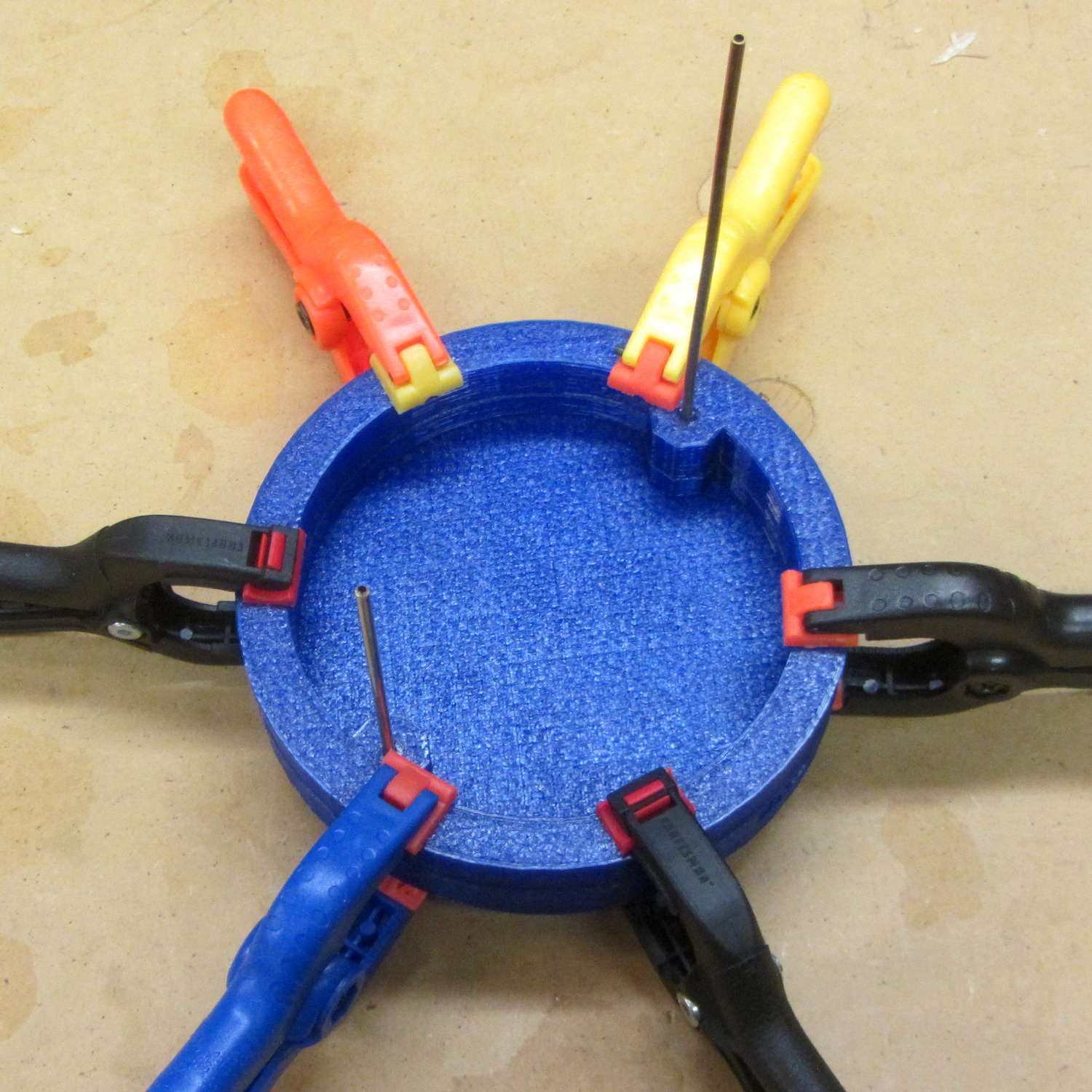
I drilled eight holes in the bottom surface of the new ring, slobbered epoxy around the ring and tucked it into the holes, used a pair of brass rods to align the two parts, and clamped them together while the epoxy cured:
Lamp Base – clamping
I should be using black PETG anyway, so we’ll call this one a prototype and move on.
For reasons not relevant here, I tore down a battery pack containing three 18650 lithium cells. After a major struggle that involved drilling access holes into the side of the case and hammering the cells free of their silicone potting restraint, I was confronted with this:
Li-ion cell – unwrapped
Battery may explode or fire if mistreated. Yeah, that could happen.
Having pretty well ignored all the warnings, the damaged cells spent two days in the cold on the patio:
Li-ion cells – safety layout
They seem unchanged, so I’ll dispose of them at the next electronics recycling event.
As it turns out, the gadget containing the pack subsequently died of a whoopise while trying to figure out how the pack’s boost regulator worked, so it joined the cells on the outgoing pile.
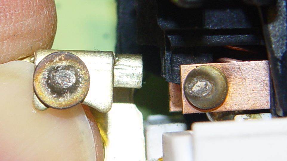
The dual switch controlling the bathroom lights began requiring some fiddling, which was not to be tolerated. After replacing the switch, I cracked the old one open to see what’s inside…
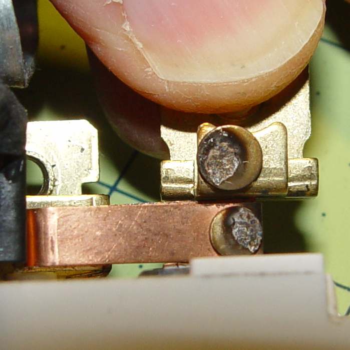
The failed side of the switch controlled the lights over the sink:
Light switch contacts – lights
The side for the ceiling vent fan + light got much less use, still worked, and look a bit less blasted.
Light switch contacts – ceiling fan
Not much to choose between the two. It’s been running for nigh onto two decades, so …