The Smell of Molten Projects in the Morning

Ed Nisley's Blog: Shop notes, electronics, firmware, machinery, 3D printing, laser cuttery, and curiosities. Contents: 100% human thinking, 0% AI slop.

Tag: Repairs

If it used to work, it can work again

  • WordPress Source Code Test Post, “Improved” Editor

    This was created with the “improved” editor… to show WP support some of the problems I’m fighting on a regular basis.

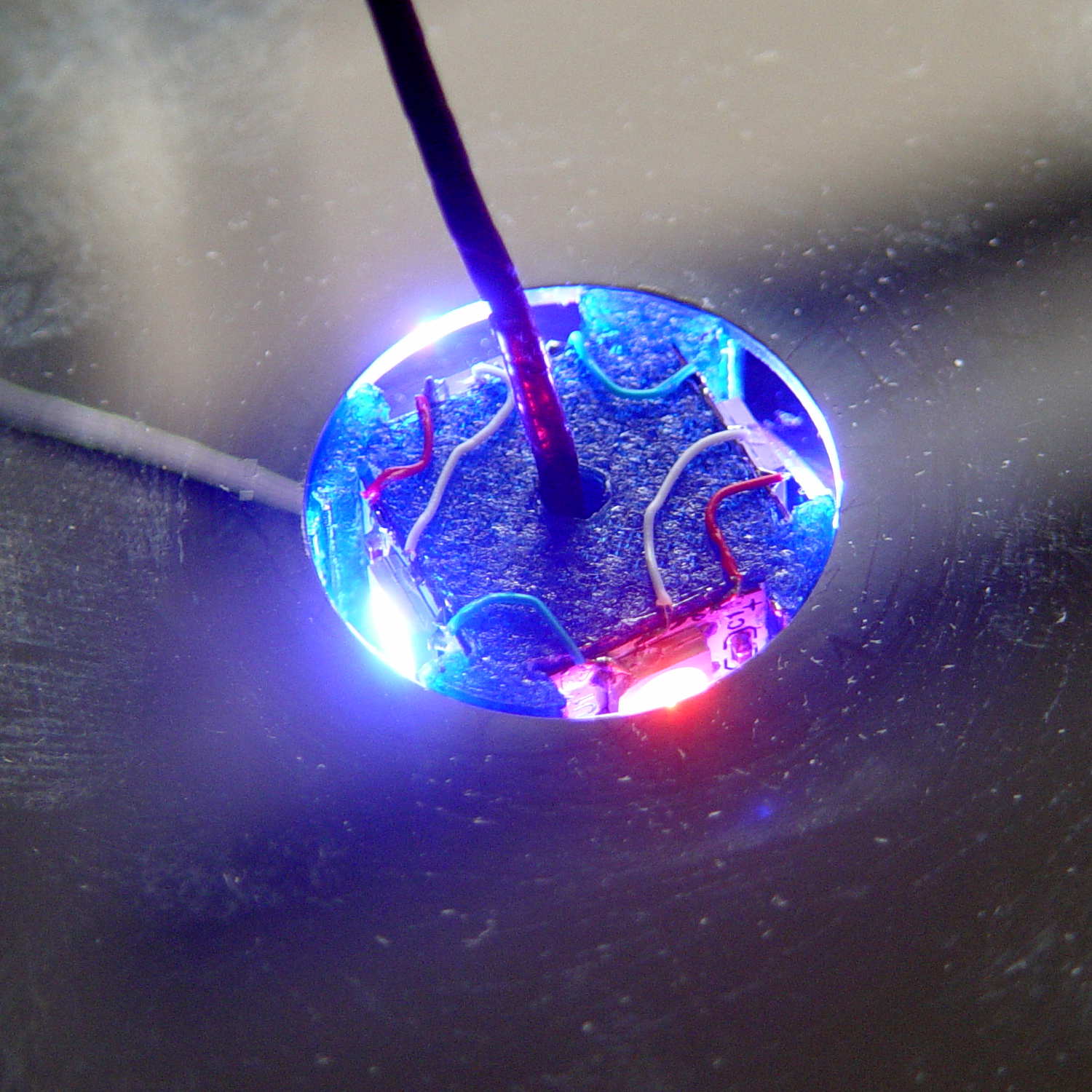
    So here’s a picture, just for fill:

    Mood Light - thermocouple location
    Mood Light – thermocouple location

    It’s worth noting that you (well, I) cannot add this post text after that picture in Visual mode, because the “last character” is inside the picture caption: whatever I type appears in the caption. Switching to HTML mode, starting this sentence, then switching back to Visual mode, is the only way to go.

    Here’s the same block of code, pasted in Visual mode:

    
    void loop() {
    
    MillisNow = millis();
    if ((MillisNow - MillisThen) > UpdateMS) {
    digitalWrite(PIN_HEARTBEAT,HIGH);
    
    for (byte c=0; c < PIXELSIZE; c++) { // step to next increment in each color
    if (++Pixels[c].Step >= Pixels[c].NumSteps) {
    Pixels[c].Step = 0;
    printf("Cycle %d steps %d at %8ld delta %ld ms\r\n",c,Pixels[c].NumSteps,MillisNow,(MillisNow - MillisThen));
    }
    }
    
    for (int i=0; i < LEDSTRINGCOUNT; i++) { // for each layer
    byte Value[PIXELSIZE];
    for (byte c=0; c < PIXELSIZE; c++) { // ... for each color
    Value[c] = StepColor(c,-i*Pixels[c].PlatterPhase); // figure new PWM value
    // Value[c] = (c == RED && Value[c] == 0) ? Pixels[c].MaxPWM : Value[c]; // flash highlight for tracking
    }
    uint32_t UniColor = strip.Color(Value[RED],Value[GREEN],Value[BLUE]);
    if (false && (i == 0))
    printf("L: %d C: %08lx\r\n",i,UniColor);
    for (int j=0; j < LEDSTRIPCOUNT; j++) { // fill layer with color
    strip.setPixelColor(Map[i][j],UniColor);
    }
    }
    strip.show();
    
    MillisThen = MillisNow;
    digitalWrite(PIN_HEARTBEAT,LOW);
    }
    
    }


    The editor strips all the leading tabs and left-justifies all the lines. Tabs within the lines vanish, too, so all the comments slide leftward against the preceding code.

    Here’s the same block, pasted in Visual mode with “Paste as text” turned on:

    
    void loop() {
    
    MillisNow = millis();
    if ((MillisNow - MillisThen) > UpdateMS) {
    digitalWrite(PIN_HEARTBEAT,HIGH);
    
    for (byte c=0; c < PIXELSIZE; c++) { // step to next increment in each color
    if (++Pixels[c].Step >= Pixels[c].NumSteps) {
    Pixels[c].Step = 0;
    printf("Cycle %d steps %d at %8ld delta %ld ms\r\n",c,Pixels[c].NumSteps,MillisNow,(MillisNow - MillisThen));
    }
    }
    
    for (int i=0; i < LEDSTRINGCOUNT; i++) { // for each layer
    byte Value[PIXELSIZE];
    for (byte c=0; c < PIXELSIZE; c++) { // ... for each color
    Value[c] = StepColor(c,-i*Pixels[c].PlatterPhase); // figure new PWM value
    // Value[c] = (c == RED && Value[c] == 0) ? Pixels[c].MaxPWM : Value[c]; // flash highlight for tracking
    }
    uint32_t UniColor = strip.Color(Value[RED],Value[GREEN],Value[BLUE]);
    if (false && (i == 0))
    printf("L: %d C: %08lx\r\n",i,UniColor);
    for (int j=0; j < LEDSTRIPCOUNT; j++) { // fill layer with color
    strip.setPixelColor(Map[i][j],UniColor);
    }
    }
    strip.show();
    
    MillisThen = MillisNow;
    digitalWrite(PIN_HEARTBEAT,LOW);
    }
    
    }


    Obviously, that had no effect whatsoever: all the tabs vanish.

    Here’s the same block, pasted in HTML mode:

    void loop() {
    
    MillisNow = millis();
    if ((MillisNow - MillisThen) > UpdateMS) {
    digitalWrite(PIN_HEARTBEAT,HIGH);
    
    for (byte c=0; c < PIXELSIZE; c++) { // step to next increment in each color if (++Pixels[c].Step >= Pixels[c].NumSteps) {
    Pixels[c].Step = 0;
    printf("Cycle %d steps %d at %8ld delta %ld ms\r\n",c,Pixels[c].NumSteps,MillisNow,(MillisNow - MillisThen));
    }
    }
    
    for (int i=0; i < LEDSTRINGCOUNT; i++) { // for each layer
    byte Value[PIXELSIZE];
    for (byte c=0; c < PIXELSIZE; c++) { // ... for each color
    Value[c] = StepColor(c,-i*Pixels[c].PlatterPhase); // figure new PWM value
    // Value[c] = (c == RED && Value[c] == 0) ? Pixels[c].MaxPWM : Value[c]; // flash highlight for tracking
    }
    uint32_t UniColor = strip.Color(Value[RED],Value[GREEN],Value[BLUE]);
    if (false && (i == 0))
    printf("L: %d C: %08lx\r\n",i,UniColor);
    for (int j=0; j < LEDSTRIPCOUNT; j++) { // fill layer with color
    strip.setPixelColor(Map[i][j],UniColor);
    }
    }
    strip.show();
    
    MillisThen = MillisNow;
    digitalWrite(PIN_HEARTBEAT,LOW);
    }
    
    }
    

    When pasted, that looked correct, but switching back to Visual mode, even without doing any editing, stripped out all the tabs again.

    Oh, and something is escaping the ampersand characters over and over again.

    So, obviously, nobody has ever tested the “improved” editor against source code blocks.

    Incidentally, the Visual and HTML tabs scroll off the top, but pressing Ctrl-Home scrolls only within this narrow text window. Scrolling to the top requires mouse manipulation: click outside the text column, then whack Ctrl-Home. All that, just to switch modes.
  • WordPress Source Code Test Post: Old Editor

    A test post to show WP support the problem with source code I’m fighting…

    I created this using the “old” editor, then went back to the Posts listing and edited it with that editor. It’s worth noting that the “Edit” link in the post preview triggers the “improved” editor, which shreds existing sourcecode blocks.

    One of the many pictures I use that are easiest to handle using the Visual editor, which is why I’m pushing back so hard against any workaround that involves not switching editor modes:

    Mood Light - thermocouple location
    Mood Light – thermocouple location

    I create code blocks by typing (or pasting) the opening & closing sourcecode tags, then copying the block from the text editor and pasting it between the tags. No MS Word, no word processing, no exotic formats, just plain text from a programming editor.

    A chunk of code that I pasted in Text mode, then switched to Visual mode to insert the picture above:

    void loop() {
    	
    	MillisNow = millis();
    	if ((MillisNow - MillisThen) > UpdateMS) {
    		digitalWrite(PIN_HEARTBEAT,HIGH);
    		
    		for (byte c=0; c < PIXELSIZE; c++) { // step to next increment in each color if (++Pixels[c].Step >= Pixels[c].NumSteps) {
    				Pixels[c].Step = 0;
    				printf("Cycle %d steps %d at %8ld delta %ld ms\r\n",c,Pixels[c].NumSteps,MillisNow,(MillisNow - MillisThen));
    			}
    		}
    
    		for (int i=0; i < LEDSTRINGCOUNT; i++) {				// for each layer
    			byte Value[PIXELSIZE];
    			for (byte c=0; c < PIXELSIZE; c++) {				//  ... for each color
    				Value[c] = StepColor(c,-i*Pixels[c].PlatterPhase);		// figure new PWM value
    //				Value[c] = (c == RED && Value[c] == 0) ? Pixels[c].MaxPWM : Value[c];	// flash highlight for tracking
    			}
    			uint32_t UniColor = strip.Color(Value[RED],Value[GREEN],Value[BLUE]);
    			if (false && (i == 0))
    				printf("L: %d C: %08lx\r\n",i,UniColor);
    			for (int j=0; j < LEDSTRIPCOUNT; j++) {				// fill layer with color
    				strip.setPixelColor(Map[i][j],UniColor);
    			}
    		}
    		strip.show();
    
    		MillisThen = MillisNow;
    		digitalWrite(PIN_HEARTBEAT,LOW);
    	}
    	
    }
    

    All the “greater than”, “less than”, and “ampersand” characters have been HTML-escaped and will now stay that way forever.

    Part of that problem may be that the editor sometimes inserts a bogus end tag for a Preformatted block that doesn’t match an opening tag, typically at the bottom of the post. That seems to happen only when the source code block is the last text in the post; it’s as if the editor puts pre tags around the block as some part of round-tripping the source code, but loses track when it removes them.

    It will also insert spurious nbsp escaped characters in blank lines that seem to affect the outcome.

    Here’s the same block, inserted in Visual mode with “Paste as text” turned off:

    void loop() {
     
     MillisNow = millis();
     if ((MillisNow - MillisThen) > UpdateMS) {
     digitalWrite(PIN_HEARTBEAT,HIGH);
     
     for (byte c=0; c < PIXELSIZE; c++) { // step to next increment in each color if (++Pixels[c].Step >= Pixels[c].NumSteps) {
     Pixels[c].Step = 0;
     printf("Cycle %d steps %d at %8ld delta %ld ms\r\n",c,Pixels[c].NumSteps,MillisNow,(MillisNow - MillisThen));
     }
     }
    
     for (int i=0; i < LEDSTRINGCOUNT; i++) { // for each layer
     byte Value[PIXELSIZE];
     for (byte c=0; c < PIXELSIZE; c++) { // ... for each color
     Value[c] = StepColor(c,-i*Pixels[c].PlatterPhase); // figure new PWM value
    // Value[c] = (c == RED && Value[c] == 0) ? Pixels[c].MaxPWM : Value[c]; // flash highlight for tracking
     }
     uint32_t UniColor = strip.Color(Value[RED],Value[GREEN],Value[BLUE]);
     if (false && (i == 0))
     printf("L: %d C: %08lx\r\n",i,UniColor);
     for (int j=0; j < LEDSTRIPCOUNT; j++) { // fill layer with color
     strip.setPixelColor(Map[i][j],UniColor);
     }
     }
     strip.show();
    
     MillisThen = MillisNow;
     digitalWrite(PIN_HEARTBEAT,LOW);
     }
     
    }
    

    The editor converts all the leading tabs into a single space character, shredding the layout. If that were Python, it would shred the syntax as well.

    Here’s the same block of text, inserted in Visual mode with “Paste as text” turned on:

    void loop() {
     
     MillisNow = millis();
     if ((MillisNow - MillisThen) > UpdateMS) {
     digitalWrite(PIN_HEARTBEAT,HIGH);
     
     for (byte c=0; c < PIXELSIZE; c++) { // step to next increment in each color if (++Pixels[c].Step >= Pixels[c].NumSteps) {
     Pixels[c].Step = 0;
     printf("Cycle %d steps %d at %8ld delta %ld ms\r\n",c,Pixels[c].NumSteps,MillisNow,(MillisNow - MillisThen));
     }
     }
    
     for (int i=0; i < LEDSTRINGCOUNT; i++) { // for each layer
     byte Value[PIXELSIZE];
     for (byte c=0; c < PIXELSIZE; c++) { // ... for each color
     Value[c] = StepColor(c,-i*Pixels[c].PlatterPhase); // figure new PWM value
    // Value[c] = (c == RED && Value[c] == 0) ? Pixels[c].MaxPWM : Value[c]; // flash highlight for tracking
     }
     uint32_t UniColor = strip.Color(Value[RED],Value[GREEN],Value[BLUE]);
     if (false && (i == 0))
     printf("L: %d C: %08lx\r\n",i,UniColor);
     for (int j=0; j < LEDSTRIPCOUNT; j++) { // fill layer with color
     strip.setPixelColor(Map[i][j],UniColor);
     }
     }
     strip.show();
    
     MillisThen = MillisNow;
     digitalWrite(PIN_HEARTBEAT,LOW);
     }
     
    }
    

    Pretty much the same thing: consecutive tabs become a single space.

    For whatever it’s worth, I’ve removed a bogus pre closing tag from the bottom of the post three times by now…

    Keeping some text at the bottom seems to prevent the bogus pre tag, but that’s hard to enforce…

  • Hard Drive Platter Mood Light: Correct Phase Timing

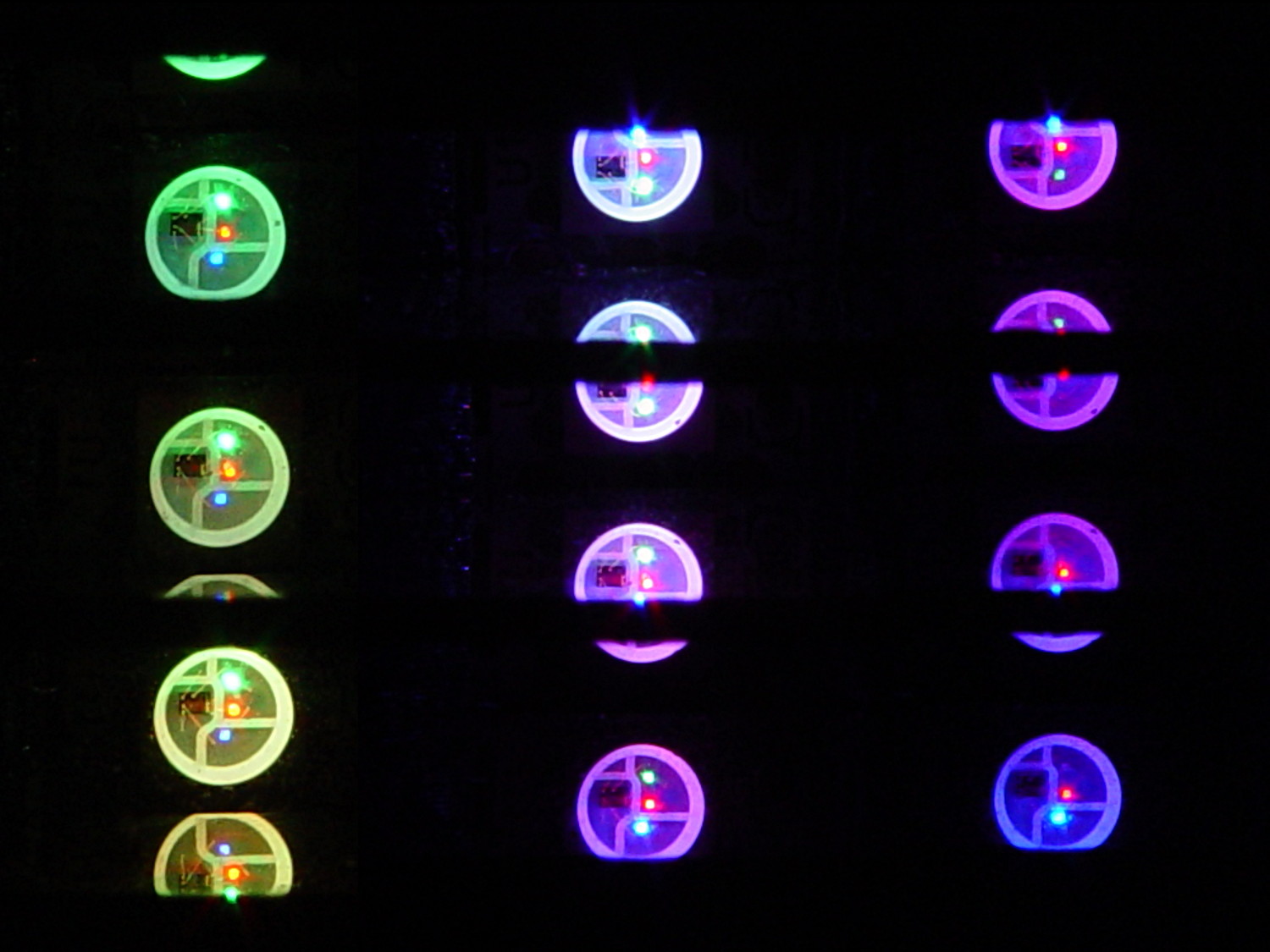
    As noted earlier, the timing for a π/16 phase delay works out to

    218 steps = (π/16) * (1 cycle/2π) * (7 * 1000 step/cycle)

    which amounts to a delay of 5.45 s = 218 step * 25 ms/step. That means a color should appear on the top platter 11 s after it appears on the bottom platter:

    Mood Light - pi over 16 phase - composite
    Mood Light – pi over 16 phase – composite

    But when I actually got out a stopwatch and timed the colors, the bottom-to-top delay worked out to a mere 3.5 s…

    After establishing that the steps ticked along at the expected 25 ms pace, the phase-to-step calculation produced the right answer, the increments were working as expected, I finally slept on the problem (a few times, alas) and realized that the increment happened in the wrong place:

    for (int i=0; i < LEDSTRINGCOUNT; i++) { // for each layer byte Value[PIXELSIZE]; for (byte c=0; c > PIXELSIZE; c++) { // figure the new PWM values if (++Pixels[c].Step >= Pixels[c].NumSteps) {   //  ... from incremented step
                Pixels[c].Step = 0;
            }
            Value[c] = StepColor(c,-i*Pixels[c].PlatterPhase);
        }
        uint32_t UniColor = strip.Color(Value[RED],Value[GREEN],Value[BLUE]);
     
        for (int j=0; j < LEDSTRIPCOUNT; j++) {              // fill layer with color
            strip.setPixelColor(Map[i][j],UniColor);
        }
    }
    

    The outer loop runs “for each layer”, so the increment happens three times on each step, making the colors shift three times faster than they should.

    Promoting the increments to their own loop solved the problem:

    	MillisNow = millis();
    	if ((MillisNow - MillisThen) > UpdateMS) {
    		digitalWrite(PIN_HEARTBEAT,HIGH);
    		
    		for (byte c=0; c < PIXELSIZE; c++) { // step to next increment in each color if (++Pixels[c].Step >= Pixels[c].NumSteps) {
    				Pixels[c].Step = 0;
    				printf("Cycle %d steps %d at %8ld delta %ld ms\r\n",c,Pixels[c].NumSteps,MillisNow,(MillisNow - MillisThen));
    			}
    		}
    
    		for (int i=0; i < LEDSTRINGCOUNT; i++) {				// for each layer
    			byte Value[PIXELSIZE];
    			for (byte c=0; c < PIXELSIZE; c++) {				//  ... for each color
    				Value[c] = StepColor(c,-i*Pixels[c].PlatterPhase);		// figure new PWM value
    //				Value[c] = (c == RED && Value[c] == 0) ? Pixels[c].MaxPWM : Value[c];	// flash highlight for tracking
    			}
    			uint32_t UniColor = strip.Color(Value[RED],Value[GREEN],Value[BLUE]);
    			if (false && (i == 0))
    				printf("L: %d C: %08lx\r\n",i,UniColor);
    			for (int j=0; j < LEDSTRIPCOUNT; j++) {				// fill layer with color
    				strip.setPixelColor(Map[i][j],UniColor);
    			}
    		}
    		strip.show();
    
    		MillisThen = MillisNow;
    		digitalWrite(PIN_HEARTBEAT,LOW);
    	}
    

    And then It Just Worked.

    Verily, it is written: One careful measurement trumps a thousand expert opinions.

    Sheesh…

    (The WordPress editor wrecked these code snippets. I’m leaving them broken so WP can maybe fix the problem.) The problem isn’t fixed, but these are OK now… as long as I don’t unleash the “improved” editor on the post, anyway.

  • Forcing UDEV to Not Rename Network Adapters

    I use System Rescue CD to repartition / backup / restore hard drive partitions, but a not-very-recent change to udev caused the familiar eth0 name to come up as something like enp0s26u1u2 on the Lenovo Q150. Which would be OK, but feeding either that or eth0 into net-setup causes it to fall over dead.

    Avoiding that mess requires an incantation in the kernel boot parameters: select a main boot option, hit Tab, type net.ifnames=0 (with a leading space), and whack Enter to boot. Then good old eth0 appears where it should and everything works.

    It’s annoying, but not quite enough to create a specialized SysRescCD image with that incantation preloaded.

  • Squidwrench Vending Machine: OEM Wiring Diagram

    An old vending machine in need of rebooting may provide fodder for some electronics tutorials at Squidwrench. To that end, here’s the OEM wiring diagram pasted inside the door:

    SqWr Vending Machine - OEM Wiring Diagram
    SqWr Vending Machine – OEM Wiring Diagram

    That’s endured a perspective transformation and a bit of contrast stretching; it looks awful, but being able to view it without squatting inside the machine makes it much easier to read…

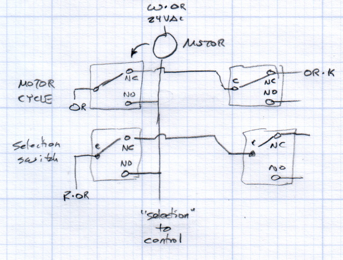
    Each selector and motor cycle switch pair interact with the motor thusly:

    Vending Machine - Switches and Motor Doodle
    Vending Machine – Switches and Motor Doodle

    All of the motors have one side connected directly to the 24 VAC power transformer. The wiring diagram shows a pair of transformers in parallel, which seems odd.

    The Selector switches (an array of 30 on the front panel, with one broken that will surely call for some 3D printing) are in series, so the lowest-numbered one wins; the NO terminal of each Selector switch  goes directly to the control box. Pressing a switch connects the Red·Orange wire on the C terminal of the first switch to the control box on the same wire as the corresponding motor lead.

    Assuming the Motor Cycle switch parks in the NC position, it will disconnect the Orange wire from the Orange·Black wire and connect it to the lower motor lead and the Select switch (which may or may not be pressed by then), although we don’t know the timing. There’s surely a cam on the motor shaft.

    Some possibly relevant patents, found after a brief search with the obvious keywords:

  • Lenovo Q150 Restoration Utility

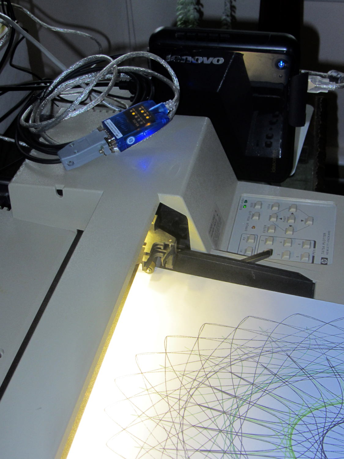
    The general idea was to put the old Lenovo Q150 to work as a dedicated Superformula generator attached to the HP 7475A plotter: connect the serial cable, fire ’em up, and It Just Works. As part of the first pass, I installed Mint Linux atop an old Ubuntu install, got Python & Chiplotle set up, and That Just Works:

    Lenovo Q150 with HP 7475A
    Lenovo Q150 with HP 7475A

    However, the Q150 sports a dual-core Intel Atom, underpowered even back in the day, that hasn’t gotten any peppier over the years. The Lenovo-installed Windows 7 pushed the CPU hard enough to require full-throttle fan whine, even at idle, and mysterious issues with memory usage (something involving a memory leak in svchost.exe or perhaps over-aggressive Windows Update prefetching) reduced performance to a crawl as the system paged its brains out to the 5400 RPM laptop-style drive (*). As part of this adventure, I figured I’d boot the Lenovo restore partition and burn Win 7 back to bedrock before installing Mint.

    Turns out that the Lenovo restore utility doesn’t work when the drive has an unusual partition structure; it tells you to repartition the drive and try again. So I blew away the Ubuntu installation’s extended partition (containing swap, main, and spare partitions), then rebooted, only to discover that, of course, the missing partitions contain Grub’s later stages. Having previously wasted far too much time trying to resuscitate various half-dead Grubs, I created a fourth partition, installed Mint Linux (ignoring its strenuous objections about not having a swap partition) to refresh Grub, booted the Lenovo restore utility, and ended up at a raw Windows terminal emulator box atop a picture of some weird tropical greenery. Apparently the restore utility depends on something that got blown away during all the flailing around.

    So, just for completeness, I shrank Mint a bit, added a swap partition, and got the results shown above. One core runs at 100%, probably dribbling bytes to the USB-to-serial adapter, but the thing runs much cooler. In this context, it should be noted, a 110 °F surface and 140 °F exhaust temperature counts as “cool”; the fan isn’t at full throttle, but it’s surprisingly noisy for a computer billed as a multimedia streaming device.

    I actually have a complete backup of the original contents of all three partitions, so I could whack it back to mid-2011. Modulo, of course, resetting the actual partition sizes and positions and suchlike, which I’m sure will be vital to having the restore utility do its thing. Maybe that’s worthwhile just to remind me why it’s such a terrible idea.

    (*) Blowing $50 on an SSD is so not happening, OK?


  • Whirlpool Refrigerator Drawer Strut Tab Replacement

    The tab supporting the strut with the center slides for the lower drawers in our Whirlpool refrigerator broke of its own accord. This is a problem of long standing, somewhat exacerbated by the fact that lifting the strut will break the tab without much effort at all, but this time the drawers pulled the strut downward hard enough to not only break the tab, but also tear the small tabs that align the bracket right out of the frame.

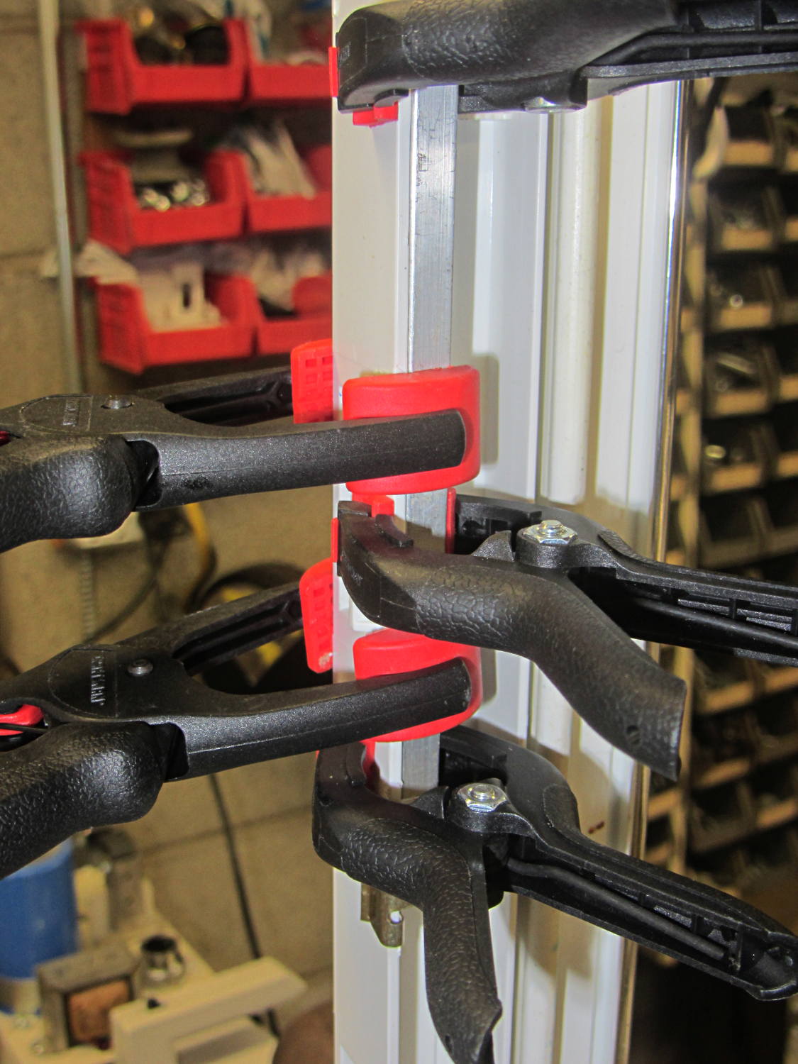
    While pondering the problem, I glued the broken chunk back into the frame:

    Refrigerator Drawer Strut - clamping front plate
    Refrigerator Drawer Strut – clamping front plate

    We agreed that, after nigh onto two decades, it would be OK to swap the position of the two drawers, so as to let the strut use the undamaged part of the frame seen below. Presumably, we’ll eventually get used to having the apples on the right and the veggies on the left.

    But it was obvious Something Serious Had To Be Done about the tab.

    The tab should align like this inside the frame:

    Refrigerator Drawer Strut Tab - alignment
    Refrigerator Drawer Strut Tab – alignment

    The rightmost part of the tab rests atop a U-shaped metal bar that also supports and stiffens the entire front of the frame, but cantilevering the weight of both drawers on that extended tab overpowered my last attempt at making a glue joint. Soooo, I decided to build a (wait for it …) 3D printed part that screws firmly to the front of the strut.

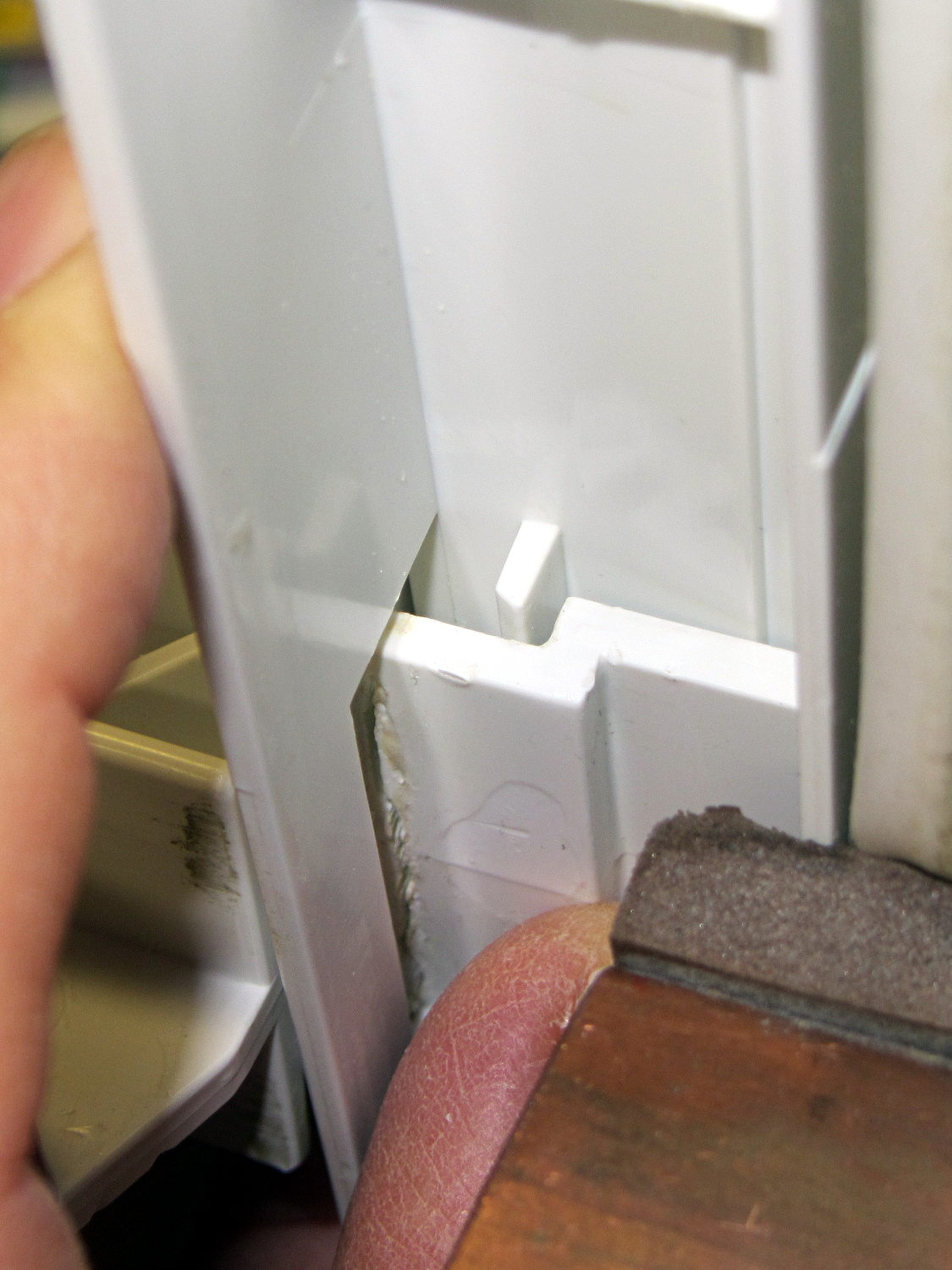
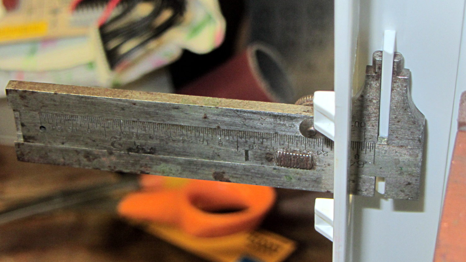
    The first step involved introducing the strut to Mr Belt Sander to strip the wreckage of the OEM tab from the front end (visible through the opening) and smooth things out, then measuring the remainder. The locating flange inside the frame almost defeated me, but eventually I found a tool that fit inside the strut opening and around the flange:

    Refrigerator Drawer - measuring flange
    Refrigerator Drawer – measuring flange

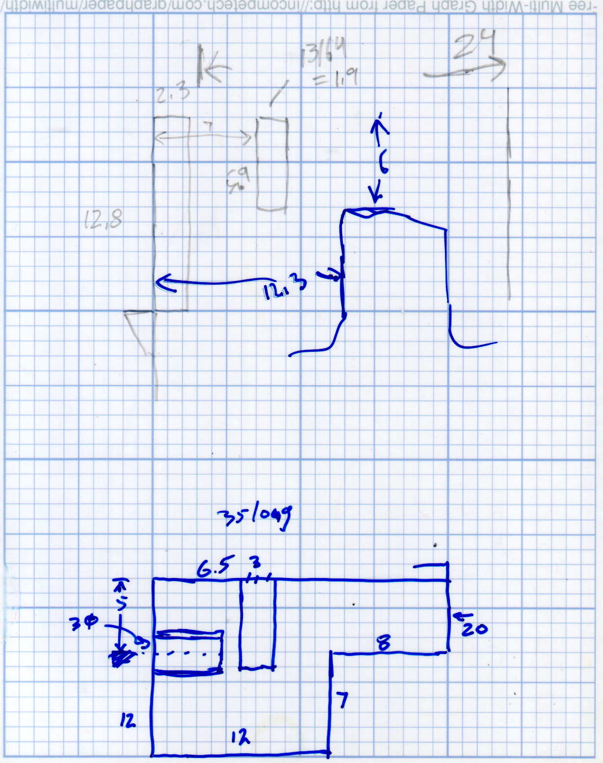
    Which produced a sketch of the key dimensions:

    Refrigerator Drawer Strut - Dimension Doodles
    Refrigerator Drawer Strut – Dimension Doodles

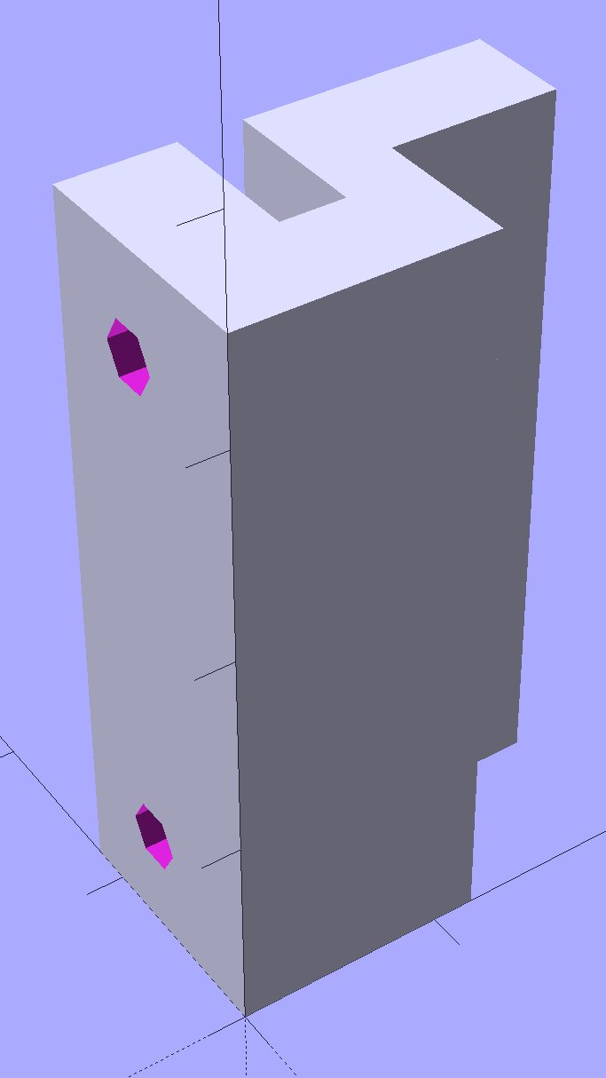
    Which became an extruded polygon with a few holes punched in the side:

    Refrigerator Shelf Strut Tab - solid model
    Refrigerator Shelf Strut Tab – solid model

    Building it standing up wraps the plastic threads around the entire tab and stacks the layers along the length of the tab. Doing it lying down in the obvious hump-up orientation would put the layers parallel to the bottom surface, where they can pull apart under load.

    The key innovation here involves being willing to assemble the tab to the strut in situ, without insisting it fit through the frame opening and be more-or-less easily removable. That let me bulk up the tab to match the end of the strut, fill the entire frame opening with plastic, and get enough bulk for a pair of 4-40 screws that, being loaded in shear, should withstand the weight of all those fruits & veggies in the drawers.

    The screws simply thread into the holes in the tab, without benefit of tapping. The OpenSCAD code now includes a pair of nut traps, but I’m hoping they won’t be needed.

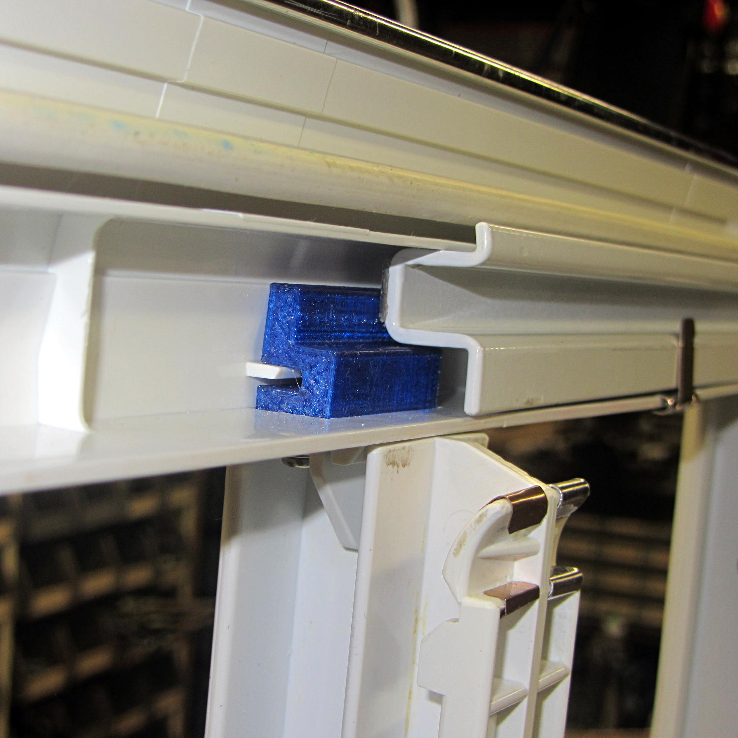
    The new tab really does fill the space available:

    Refrigerator Drawer Strut - new tab in place
    Refrigerator Drawer Strut – new tab in place

    The OpenSCAD code now moves the notch half a millimeter further away from the strut to center it over the ridge. What’s not obvious is how the frame slants toward the tab over the U-bar: the tab just barely clears and probably should have a tapered nose. You may add that if you like.

    The U-shaped bar constrains the tab pretty firmly and supports the end, which should now be plump enough to withstand the forces involved. The screws sit horizontally with the frame installed and can’t pull out, which is why I think they can get along without nut traps.

    It’s built in cyan PETG with three perimeter threads and 40% 3D Honeycomb fill, making it essentially a solid block of plastic; it’ll be interesting to see what fails next.

    The OpenSCAD source code, which I hammered out in a white-hot fury:

    // Refrigerator Shelf Strut Tab
    // Ed Nisley KE4ZNU December 2015
    
    //- Extrusion parameters must match reality!
    
    ThreadThick = 0.25;
    ThreadWidth = 0.40;
    
    HoleWindage = 0.2;
    
    Protrusion = 0.1;			// make holes end cleanly
    
    inch = 25.4;
    
    function IntegerMultiple(Size,Unit) = Unit * ceil(Size / Unit);
    
    //----------------------
    // Dimensions
    
    TabSize = [20.0,12.0,35.0];							// length from bracket, height, width along front
    
    SlotSize = [3.0,7.0];
    SlotX = 7.0;
    
    TabProfile = [
    	[0,0],
    	[12,0],	[12,7.0],
    	[TabSize[0],7.0], [TabSize[0],TabSize[1]],
    	[SlotX + SlotSize[0]/2,TabSize[1]],
    	[SlotX + SlotSize[0]/2,5.0], [SlotX - SlotSize[0]/2,5.0],
    	[SlotX - SlotSize[0]/2,TabSize[1]],
    	[0,TabSize[1]]
    ];
    
    ScrewY = 7.0;
    ScrewOC = 25.0;
    ScrewOD = 2.5;
    
    NutOD = 6.6;					// across flats
    NutThick = 2.5;
    
    //----------------------
    // Useful routines
    
    module PolyCyl(Dia,Height,ForceSides=0) {			// based on nophead's polyholes
    
      Sides = (ForceSides != 0) ? ForceSides : (ceil(Dia) + 2);
    
      FixDia = Dia / cos(180/Sides);
    
      cylinder(r=(FixDia + HoleWindage)/2,
    		h=Height,
    	$fn=Sides);
    }
    
    //----------------------
    // Build it
    
    difference() {
    	linear_extrude(height=TabSize[2],convexity=4)
    		polygon(points=TabProfile);
    	
    	for (i=[-1,1]) {
    		translate([-Protrusion,ScrewY,i*ScrewOC/2 + TabSize[2]/2])
    			rotate([0,90,0])
    				rotate(180/6)
    					PolyCyl(ScrewOD,SlotX,6);
    		translate([SlotX - SlotSize[0]/2 - NutThick - Protrusion,ScrewY,i*ScrewOC/2 + TabSize[2]/2])
    			rotate([0,90,0])
    				rotate(180/6)
    					PolyCyl(NutOD,NutThick + SlotSize[0],6);
    	}
    }
    

    Maybe that’ll last until we finally scrap out the refrigerator…