Ed Nisley's Blog: Shop notes, electronics, firmware, machinery, 3D printing, laser cuttery, and curiosities. Contents: 100% human thinking, 0% AI slop.
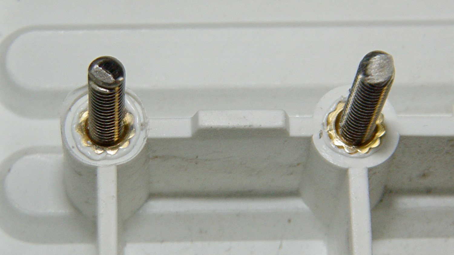
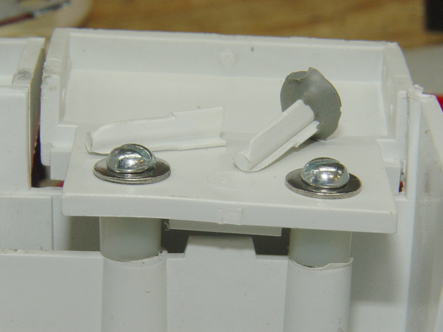
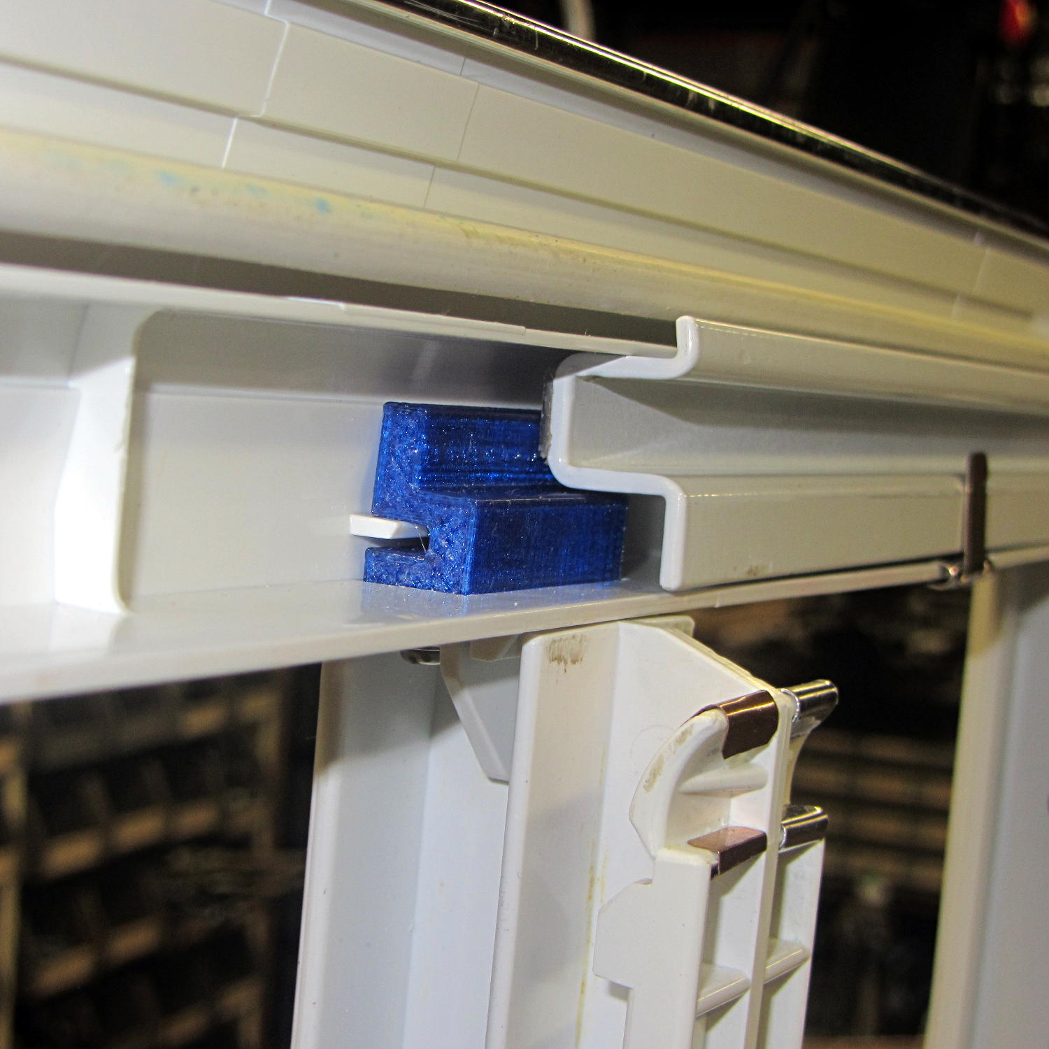
I discovered that 4-40 knurled inserts perfectly match the available space, so I drilled the 3D printed holes out to 11/16 inch (the OD of the smaller knurls) and rammed the inserts into place:
Looks much better, ought to work just as well, and will definitely outlive the refrigerator; if I never take that thing apart again, it’ll be fine with me.
This steel strip emerged from inside the arm of the Kenmore 158.17032 sewing machine that we’ve been reconditioning for one of Mary’s friends:
Kenmore 158.17032 – mystery spring
The ends show the granular fracture of hard steel:
Kenmore 158.17032 – mystery spring – end view
It’s 13.3 mm long, 1.0 mm thick, tapers slightly from 2.8 mm on the end that once said “Japan” to 2.76 mm on the other, and that’s all we know about it.
The sewing machine seems to work well enough without it (after some clean-and-lube action) and we haven’t found where the piece came from, but circumstantial evidence suggests it’s part of a spring somewhere inside the arm. It’s in a little bag with all the other random sewing machine parts I’ve collected along the way; perhaps some day we’ll know more and I can fabricate a replacement.
One of Mary’s friends asked us to take a look at her Kenmore 158.17032 sewing machine that suffered from a Showstopper Problem: the handwheel turned the main shaft, but the motor pulley spun freely. You could rev the motor to maximum speed without budging the shaft, which suggested something was wrong with the clutch joining the handwheel and the belt pulley to the main shaft. This being a slightly newer model than the others in our stable, I was mildly surprised to find a completely different clutch mechanism between the drive belt and the main shaft.
The plastic cover plate in the handwheel yielded to an old crochet hook:
Kenmore 158.17032 – Handwheel cap removal
Stick the hook into the tiny notch, engage hook with cover, pull outward, and it’ll fall into your other hand.
That exposes a simple screw holding the chromed plastic handwheel in place on the motor shaft. After taking the pulley and clutch off the Hard Way, I discovered the Right Way, which is hereby documented for The Next Time Around. In order to show what’s needed, I’ll start in the middle and work outward.
Pull the handwheel off and remove the machine’s end cover.
With the clutch assembly removed (which you can’t do yet), you can see a pair of pot metal bands that act as a brake when the bobbin winder snaps off a full bobbin. They look like this in the normal running position:
Kenmore 158.17032 – Clutch trip lever – normal position
The black bow-tie at 9 o’clock is vertical, holding the brake bands apart and clearing the tab on the clutch asembly (which you haven’t seen yet).
They look like this when the bobbin winder has just snapped:
Kenmore 158.17032 – Clutch trip lever – bobbin wind position
The Bobbin Winder Reset Button atop the machine (which our machines don’t have and this one does) presses on the tab sticking out toward you on the horizontal bar pivoting on the front of the machine:
Kenmore 158.17032 – Bobbin winder reset lever
In that position, the button is up, the bobbin is ready to load, the brake bands are off, and you can gently tap the clutch assembly off the main crankshaft:
Kenmore 158.17032 – Handwheel clutch assembly
The inner hub rotates very slightly with respect to the belt drive pulley (which has the grooves that drive the bobbin winder tire). That didn’t quite work on this machine, due to the usual lack of lubrication / mechanical wear / what-have-you.
The innermost part (with the notches for the pin visible at 2 o’clock on the main shaft) rotates with the handwheel. The belt pulley rotates with the motor belt. The clutch lets you turn the handwheel with the motor stopped. Normal rotation is clockwise in this view; on the machine, you turn the top of the wheel toward you.
Carefully remove the spring that retracts the clutch lever, remove both black screws, remove the big flat head screw, and slide the black lever out to the side.
Unscrew the two remaining flat-head screws holding the hub / lever in place. The one with the longer shoulder goes into the lever:
Kenmore 158.17032 – Handwheel clutch screws
Removing the hub reveals the pin that engages the clutch mechanism visible through the slot at 6 o’clock in the handwheel:
Kenmore 158.17032 – Handwheel clutch dog
Remove the fiber washer and the steel cover plate to expose the clutch mechanism:
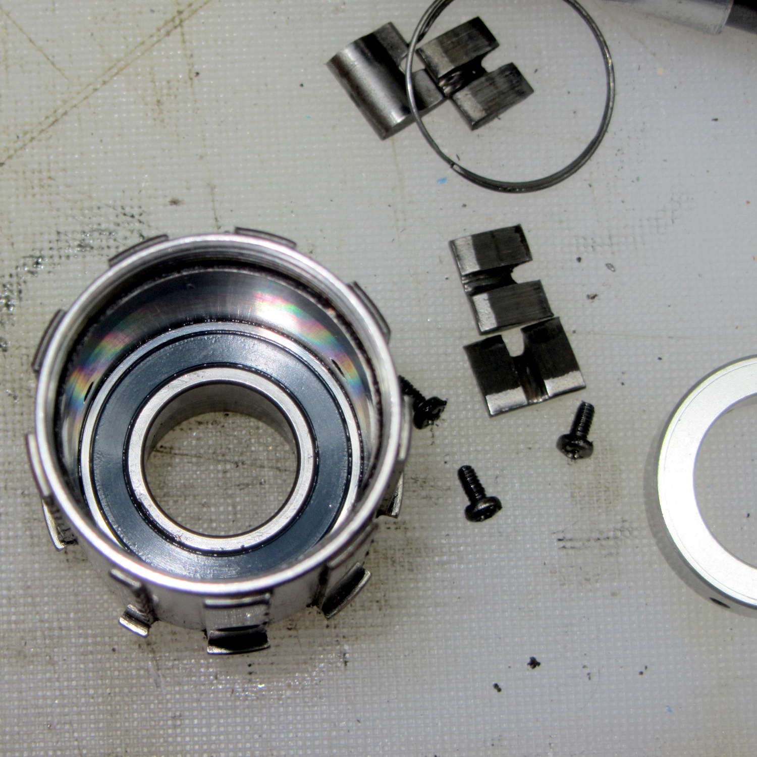
Kenmore 158.17032 – Handwheel clutch – detail
The pin pressing against the hollow cylinder (which is the actual clutch!) has a powerful spring:
Kenmore 158.17032 – Handwheel clutch interior
If you hold the cylinder in place, you can rotate the clutch body enough to unload the spring just enough to let you ease the cylinder out and gently release the spring. Good luck!
With all the parts on the bench, clean everything, lube only the parts that need it (like the spring-loaded pin, but not the clutch cylinder), put everything back together, and it should Just Work.
The screwdriver points out the tab engaging the black bow-tie doodad:
Kenmore 158.17032 – Handwheel clutch tab
The object of the games is to make the tab pivot smoothly around the large flat-head screw under the spring as you press the part that sticks out, so the clutch will be either completely disengaged or firmly engaged.
When you get it working smoothly, release the brake bands, slide the clutch assembly back on the shaft, reinstall the cover, install the handwheel, install the screw, pop the plastic hub back in, and you’re done!
Update:
Even though I write this stuff down to help me remember what I did, sometimes other folks find it useful:
Just read your article about Kenmore 158.17032 Handwheel clutch and was able to repair a machine because of you. I so appreciate that you take the time to post such things. I would not have taken the thing apart had I not found your article and I just wanted to say THANKS. I browsed some of your other projects also. Wow.
Thanks Again,
Donnie
… and …
I have spent weeks searching for how to fix the Kenmore 158.1703 clutch ( a very weird one) for a friend of mine. I was pointed to your post by the Vintage Kenmore sewing machine groups.io. I jumped up and down with joy to read and see the photos. Yes! I can fix this and get it back to her. THANK YOU! I will try later today with your post printed out. Thank you! Linda
More small victories in the struggle against entropy!
It seems that two years is about as long as the NP-FS11 batteries last, as shown by the two lower curves from the ones I rebuilt in December 2013 with cells from 2011:
Sony NP-FS11 2011-2016 Packs
The two middle curves with those same colors show the “back then” performance of those batteries: they’re shot in both total capacity and terminal voltage.
I bought enough cells back in 2011 to leave two cells unused until now, which I built into a pack and charged. The green curve in the middle shows the result: those cells haven’t lost anything over the last five (!) years, as their performance still matches the other two batteries when they were new.
The red curves come from a pair of batteries made with fresh new cells from batteryspace.com. They’re nominally 650 mA·h cells, so the NP-FS11 configuration (two parallel cells) should produce 1300 mA·h; surprisingly, they show 1500 mA·h with a nice voltage curve.
So, although the 2011 cells work as well as their (now defunct) siblings, that pack can’t deliver the same capacity as the new cells. I expect I’ll rebuild it with 2016 cells in about a year.
For whatever it’s worth, rebuilding these batteries goes much faster when I don’t have to saw them open. The Kapton tape wrapped around the case halves secures them well enough; there’s no need for fancy gluing.
NP-FS11 Battery Rebuilds – 2016-03
Yeah, I should make better labels. It’s hard to form a deep emotional attachment to the poor things, though.
Here’s a case where something performs better than expected; I don’t always buy cheap junk from the usual eBay vendor…
Although Mary liked the illumination from her OttLite (an old 13 W fluorescent Folding Task Lamp), neither of us liked its tiny base and tippy nature. It recently fell / was dropped / jumped to its doom, smashing the CFL tube and wreaking havoc on the tiny plastic studs holding its large cast-iron weight and steel base in position. Given that the CFL ballast had started humming a while ago, I took it apart to see whether I could salvage anything from the rubble.
Remove:
Four screws under the fuzzy felt feet
One screw under the label on the back
A final screw that becomes visible only after disemboweling the hinge assembly by unscrewing the obvious endcaps:
OttLite LED Conversion – hinge screw
Pull the hinge end of the white inside panel away from the outer stand at enough of an angle to disengage all three latches holding it to the base, then remove it just enough to let you start cutting wires around the ballast…
I rebuilt the thing with a pair of 24 V 150 mA warm-white LED panels (good industrial surplus, not the usual cheap eBay crap) powered by a 19 V laptop adapter (from IBM, no less) through a (cheap eBay) boost converter sticky-foam-taped where the fluorescent ballast used to live:
OttLite LED Conversion – boost supply wiring
The power supply had only two conductors, the central wire surrounded by twisted shielding, and didn’t require a fussy interface. Hooray for simple bulk power supplies; I lopped off the connector and soldered the wires directly to the boost converter.
The original lamp wiring has a 120 VAC switch inside the hinge that turned the lamp on as you raise the arm holding the CFL tube: exactly what I need for its new use. That eliminated figuring out how to crack the arm apart to rewire it.
I harvested the base from a(nother) defunct CFL bulb:
OttLite LED Conversion – harvested CFL base
By soldering wires directly into the pins, I could reuse the existing CFL socket in the lamp arm, the existing wiring, and the switch.
The LED panels dissipate 3-ish W each:
OttLite LED Conversion – LED panel layout
They’re mounted on a 0.1 inch aluminum sheet from the heap that required exactly one saw cut to fit into the space available, so I defined it to be perfect. The 4-40 screws holding the panels in place continue through the plate and 3/8 inch aluminum standoffs into a quartet of knurled inserts epoxied into eyeballometrically match-drilled holes in the lamp arm:
OttLite LED Conversion – epoxied threaded inserts
The faint yellowish discoloration from the CFL tube’s heat and UV is much more visible in real life, but nobody will ever see it again. The scrawled blue (+) and (-) marks give the socket polarity; it’s not mechanically polarized and a bit of care is in order. The black rectangle is actually a shiny metal sheet intended to reflect heat from the CFL tube’s base away from the plastic arm.
I set the boost converter to 23.5 V, at which point the LED panels draw about 100 mA each and get just over uncomfortably warm after an hour or two:
OttLite LED Conversion – in action
The panels run 120 °F = 50 °C and the SMD LEDs probably exceed 150 °F = 65 °C. The scant surplus doc touted “No heatsink required” and the single-sided FR4 PCB insulates the LEDs from the aluminum sheet, but I still smeared some heatsink compound behind the panels in the hopes of spreading the heat out a bit.
I glued the shattered base studs back in place with IPS #3, surrounded them with generous epoxy fillets, plunked the cast iron weight in place atop some waxed paper to mold the epoxy to fit (and let me remove it again, if needs be), screwed everything together, and stuck a foam sheet over the steel base plate. It’s as tippy as before, but at least the LEDs won’t shatter if when it falls. It really needs a larger base; a polycarbonate plate might work, if only I could figure out how to attach it.
All in all, the lamp looks good and the warm-white LEDs with DC drive don’t produce that horrible fluorescent flicker.
The lamp now sports a label identifying it as a NisLite; because P-Touch labeler.
A few months back, the 13-tooth sprocket on my Tour Easy started skipping, which reminded me that I planned to replace all the drivetrain components. Time passed, the winter remained unseasonably warm and sunny, we kept riding, the skipping got much worse, and I just shifted across that sprocket.
Finally, the rains returned, I heaved the bike up on the workstand, and started replacing things. Judging from the accumulated crud and severe wear, it’s been on there for quite a while:
Sprocket with broken teeth – as found
Here’s the offending 13-tooth sprocket, all shined up;
Sprocket with broken teeth – detail
I don’t recall a catastrophic failure that stripped all those teeth off in one shot. A closer look showed cracks in the few remaining teeth:
Sprocket with broken teeth – cracked teeth
Which explains why the skipping gradually got worse: the poor sprocket shed teeth as I rode blithely along.
Huh.
That’s what happens with a severely worn sprocket: the chain applies tension to just the topmost tooth, rather than distributing it on the teeth around a third (or more) of the sprocket, and, one by one, that force breaks the teeth. The top picture shows at least one other sprocket with a missing tooth; all display the shark-fin profile of heavy wear.
As you can tell from the other bike pix & repairs around here, I’d rather ride than mess around with cleaning and suchlike. We’re on our second set of drivetrain components in 15 years, so I’d say treating all that stuff as consumable seems a fair tradeoff…
It stopped changing colors and began blinking high-intensity bursts of the RGB LEDs. Which was interesting, I’ll grant you, but didn’t produce the desired, ah, mood.
It’s been plugged into a Kill-a-Watt meter that reports it ran for 415 hours and used 150 W·h of energy, for an average 360 mW dissipation. I think the actual power falls well below the meter’s lower limit, so I doubt the accuracy, but it’s a whole bunch less than a nightlight and much more interesting.
Now, to break that epoxy bond without breaking the bulb …