The Smell of Molten Projects in the Morning

Ed Nisley's Blog: Shop notes, electronics, firmware, machinery, 3D printing, laser cuttery, and curiosities. Contents: 100% human thinking, 0% AI slop.

Tag: Mini-lathe

Tweaking an LMS 5200 Mini-Lathe

  • MPCNC Drag Knife: PETG Linear Bearing

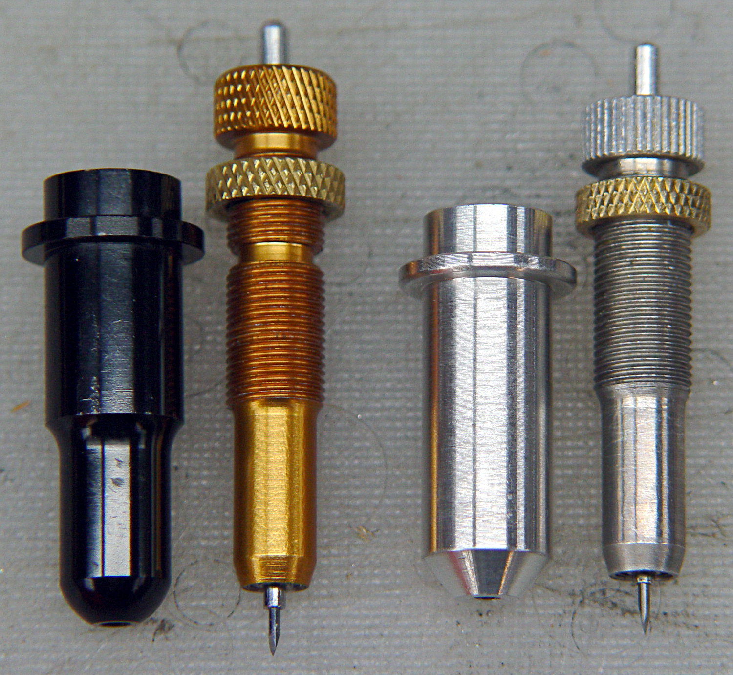
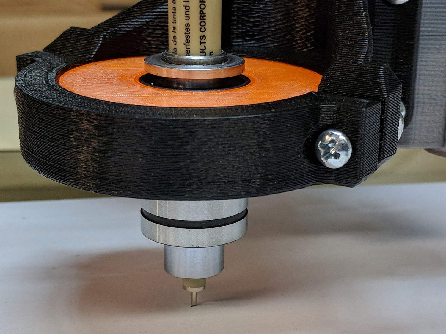
    Having reasonable success using a 12 mm hole bored in a 3D printed mount for the nice drag knife holder on the left, I thought I’d try the same trick for the raw aluminum holder on the right side:

    Drag Knife holders - detail
    Drag Knife holders – detail

    The 11.5 mm body is long enough to justify making a longer holder with more bearing surface:

    Drag Knife Holder - 11.5 mm body - Slic3r preview
    Drag Knife Holder – 11.5 mm body – Slic3r preview

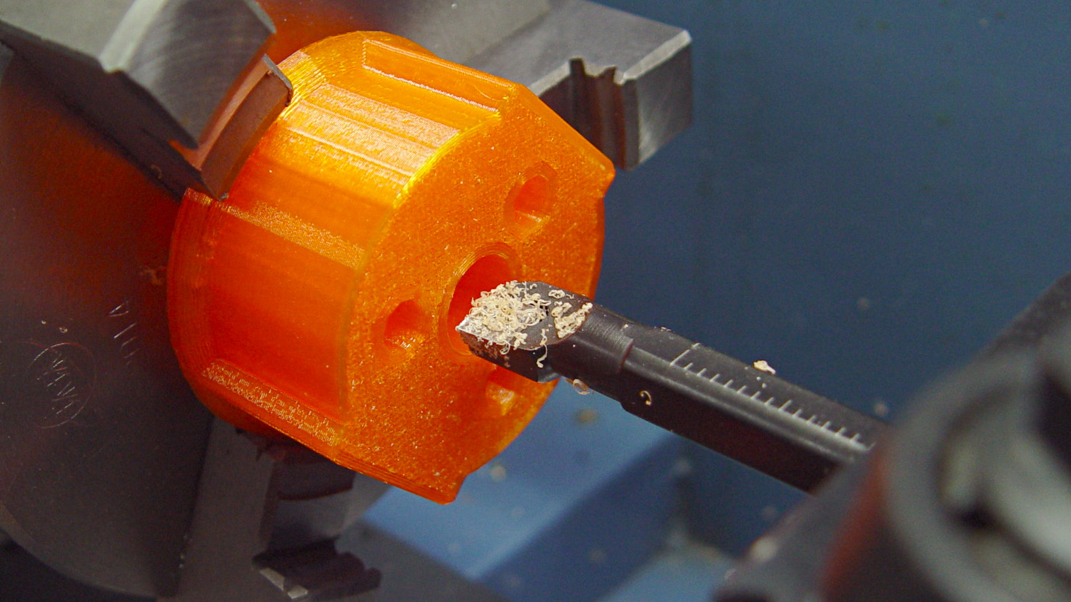
    Slicing with four perimeter threads lays down enough reasonably solid plastic to bore the central hole to a nice sliding fit:

    Drag Knife - 11.5 mm body - boring
    Drag Knife – 11.5 mm body – boring

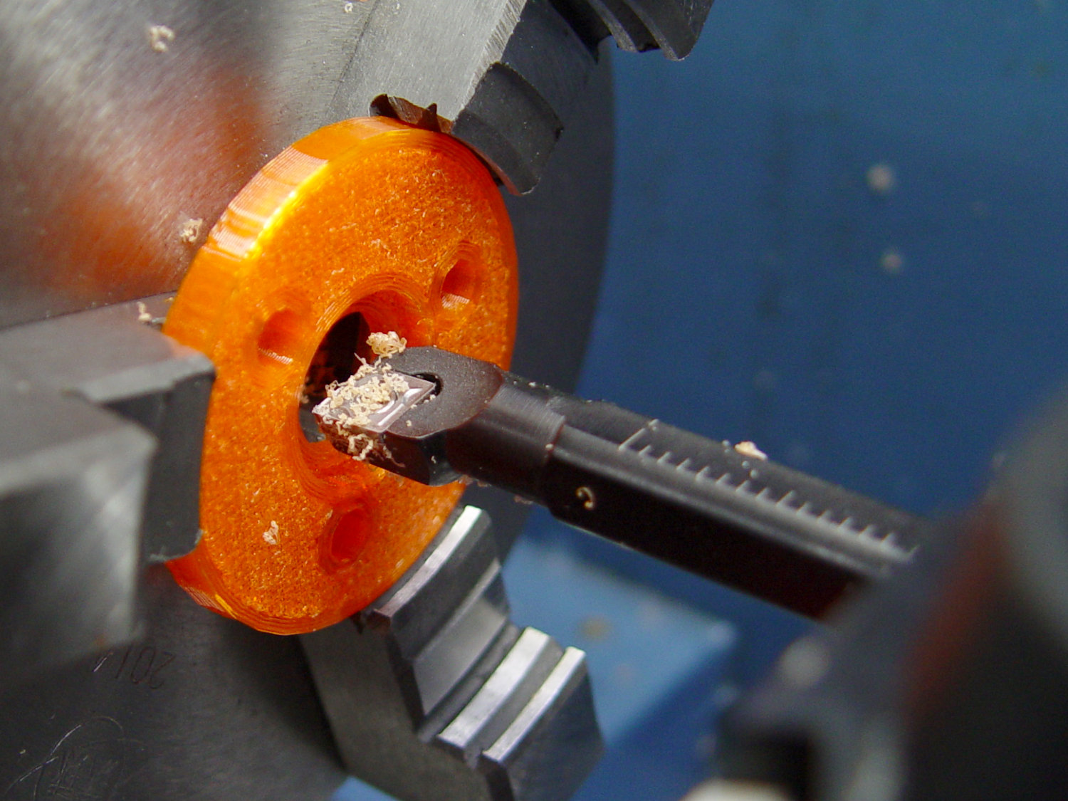
    The top disk gets bored to a snug press fit around the flange and upper body:

    Drag Knife - 11.5 mm body - flange boring
    Drag Knife – 11.5 mm body – flange boring

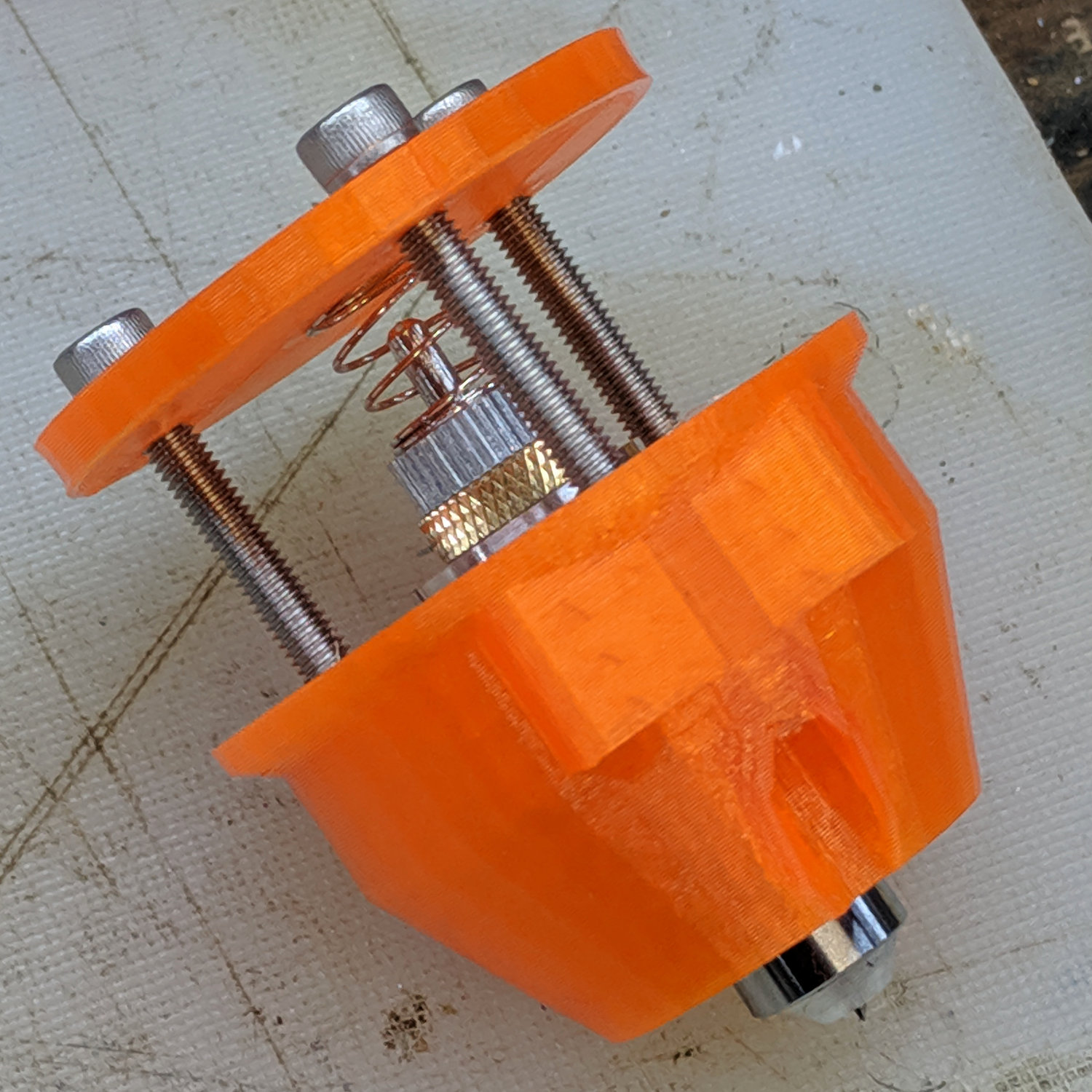
    Assemble with springs and it pretty much works:

    Drag Knife - hexagon depth setting
    Drag Knife – hexagon depth setting

    Unfortunately, it doesn’t work particularly well, because the two screws tightening the MPCNC’s DW660 tool holder (the black band) can apply enough force to deform the PETG mount and lock the drag knife body in the bore, while not being quite tight enough to prevent the mount from moving.

    I think the holder for the black knife (on the left) worked better, because:

    • The anodized surface is much smoother & slipperier
    • The body is shorter, so less friction

    In any event, I reached a sufficiently happy compromise for some heavy paper / light cardboard test shapes, but a PETG bearing won’t suffice for dependable drag knife cuttery.

    Back to the laboratory …

  • Improved Shoelace Ferrule Aglets

    After considerable evaluation, the Customer decided the shoelaces were still too long and said the hex-crimped ferrules were entirely too rough and tended to snag on things. This time, I prepared the ferrules by chucking them in the lathe:

    Ferrule - original flange
    Ferrule – original flange

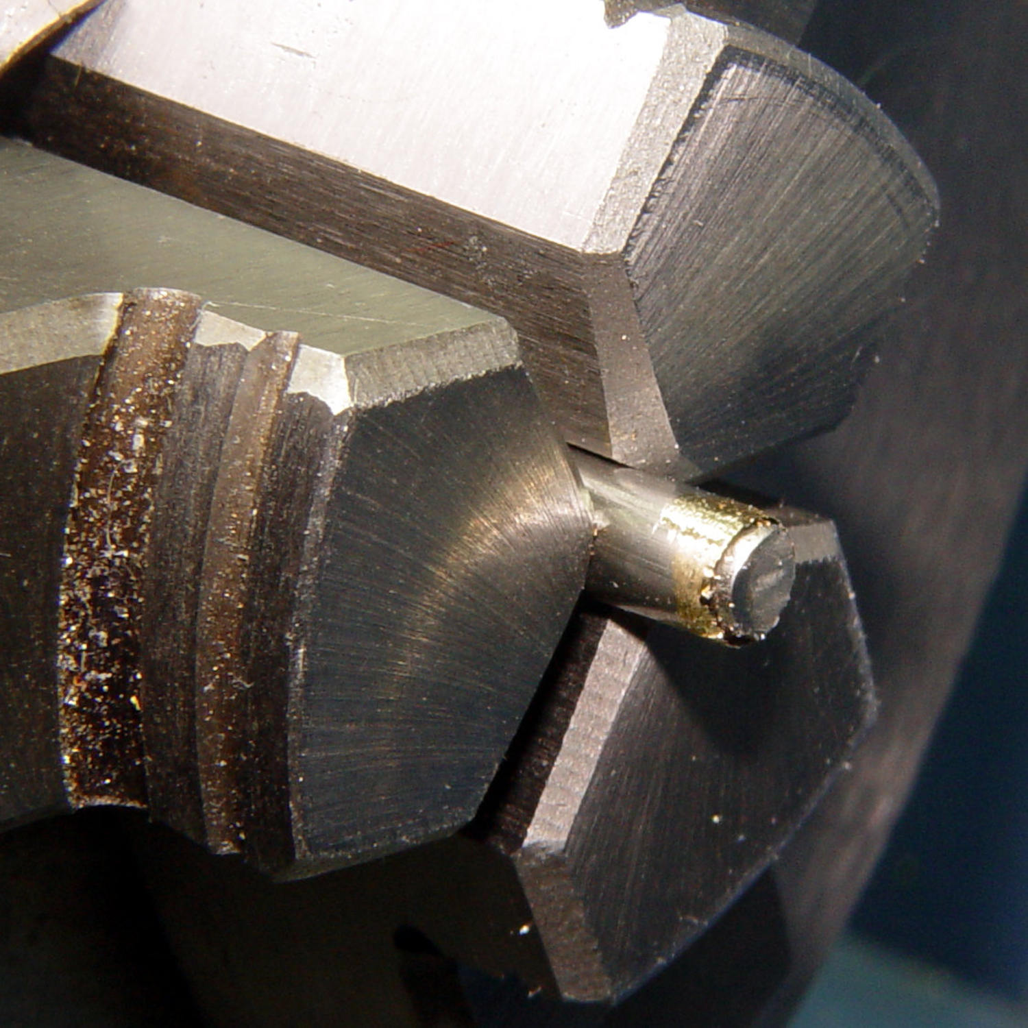
    The steel rod inside the ferrule encourages it to remain round and not collapse while I’m filing off the flange that normally holds the plastic strain-relief doodad:

    Ferrule - reshaped flange
    Ferrule – reshaped flange

    I snipped another half inch off each end of the laces and crimped on the prepared ferrules:

    Shoelace ferrule aglets
    Shoelace ferrule aglets

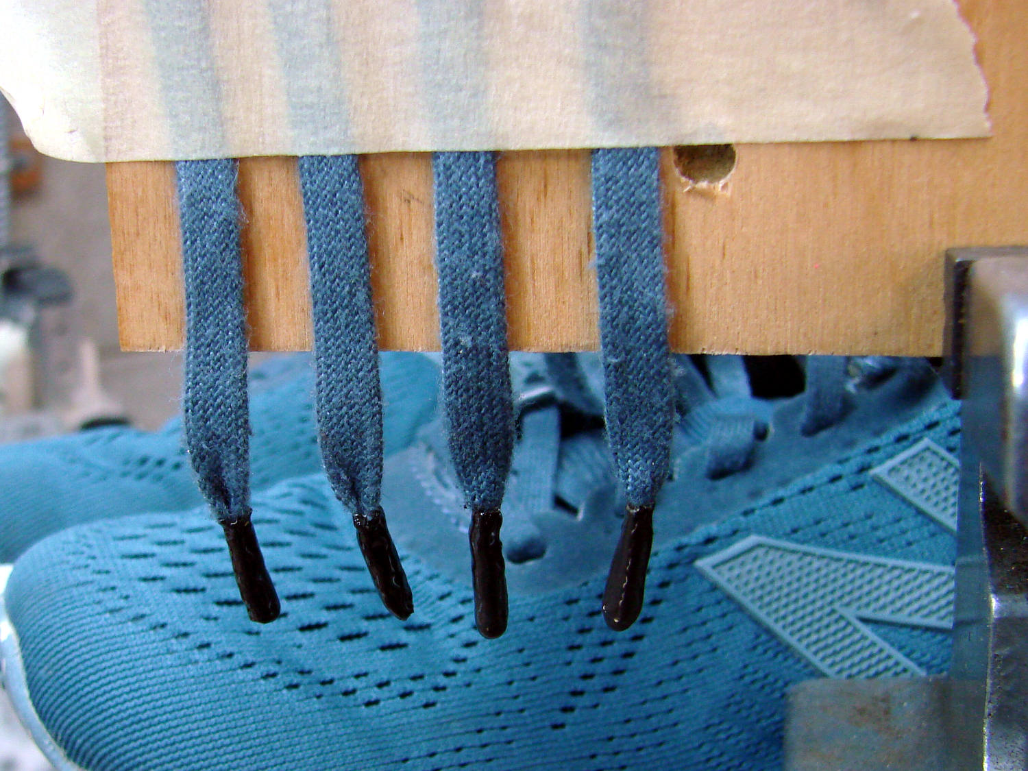
    Which were definitely too jaggy, so they now sport an epoxy coat:

    Ferrule aglets - epoxy coat
    Ferrule aglets – epoxy coat

    Alas, JB Kwik epoxy has a pot life measured in minutes, so the last ferrule looks a bit lumpy. They seem to work fine and the Customer is happy with the results.

    Memo to Self: Next time, dunk the ferrules in a pot of slow-curing JB Weld and let them drain overnight.

  • Minilathe MT3 Spindle Collet Fitting

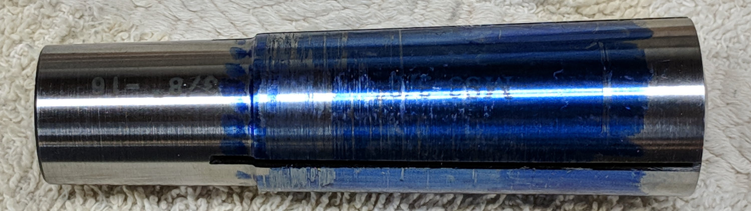
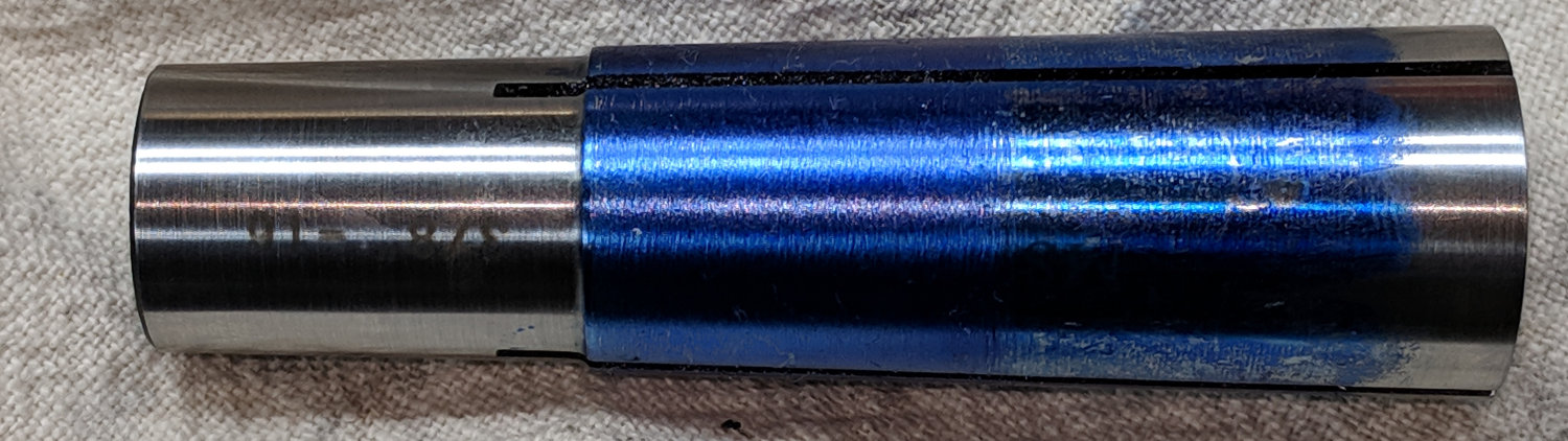
    I’ve used the LMS set of inch-size MT3 spindle collets on occasion, but releasing them required an unseemly amount of drawbar battering. It recently occurred to me to check their fit in the spindle taper:

    Minilathe - MT3 collet - taper test
    Minilathe – MT3 collet – taper test

    Huh.

    The only place they touch the spindle is right around the base, so it’s no wonder they clamp poorly and release grudgingly. I tried several others with the same result.

    Cross-checking shows a much closer fit along the entire length of the dead center, so it’s not the spindle’s fault:

    Minilathe - Dead Center - MT3 taper check
    Minilathe – Dead Center – MT3 taper check

    Stipulated: we’re not talking toolroom precision here

    I set the collets on centers:

    Minilathe - MT3 collet - drive setup
    Minilathe – MT3 collet – drive setup

    And proceeded to file away the offending section to move the clamping force closer to the business end of the collet:

    Minilathe - MT3 collet - filed result
    Minilathe – MT3 collet – filed result

    I did the small collets, the ones I’m most likely to need, and left the big ones for another rainy day.

    They don’t have much clamping range and seem good only for exact-inch-size rods.

    I should lay in a stock of ER16 and maybe ER32 collets for small stuff.


  • Bird Feeder Unbending

    At some point in its history, the left rail holding the wood perch on our industrial-strength “squirrel proof” seed feeder took a hit, most likely from being dropped:

    Squirrel on bird feeder
    Squirrel on bird feeder

    I finally got a Round Tuit and un-bent the poor thing:

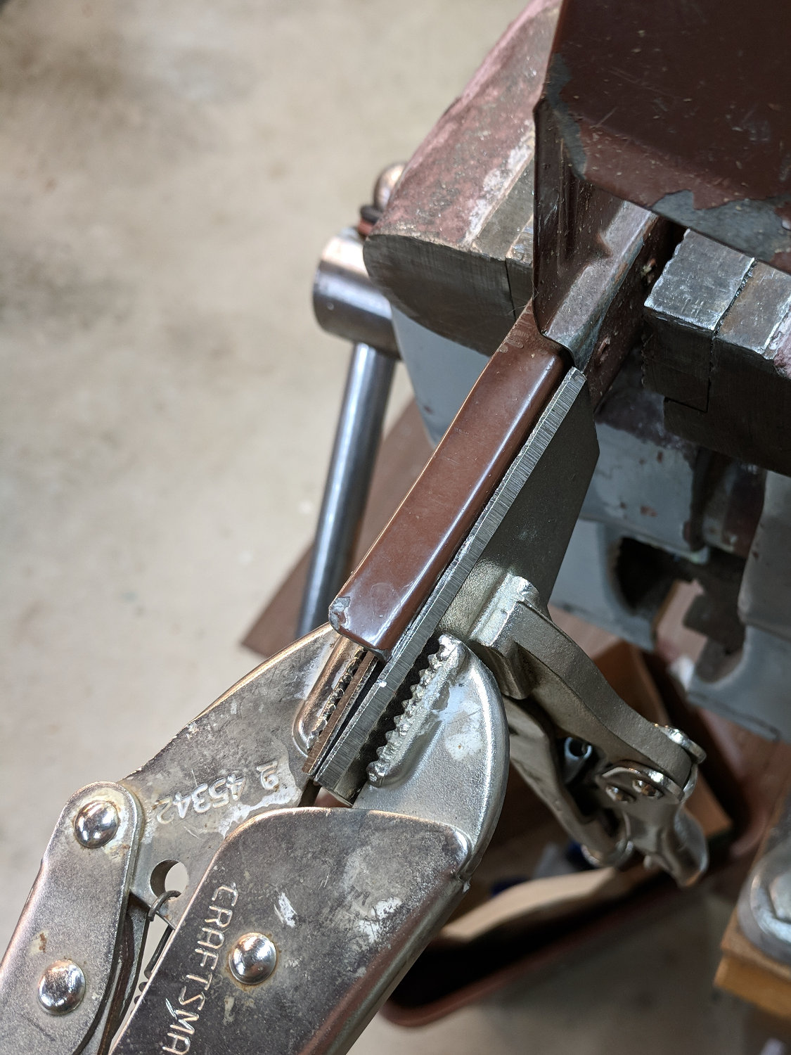
    Bird feeder - rail un-bending
    Bird feeder – rail un-bending

    Because the bend happened at the base of the vertical strut holding the shutter, I clamped a Genuine Vise-Grip sheet metal pliers along the straight section. The Craftsman knock-off Vise-Grip then applied torque at the bend, rather than just making things worse, and some two-axis tweakage lined up the rail pretty well.

    With the bend taken care of, I clamped the rail in the bench vise with some scrap wood around the strut:

    Bird feeder - warped rail
    Bird feeder – warped rail

    A percussive adjustment jam session flattened the top flange, leaving both sections as flat as they’re gonna get.

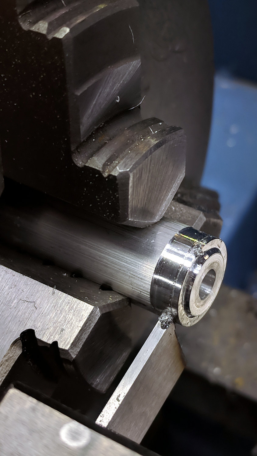
    While I was at it, I turned a pair of stepped aluminum washers for the new wood rod:

    Bird feeder - parting off washer
    Bird feeder – parting off washer

    Which looked about like you’d expect, including a little chatter from the cut off tool:

    Bird feeder - perch hardware
    Bird feeder – perch hardware

    Yeah, I drilled the wood rod on the lathe, too; I loves me some simple lathe action.

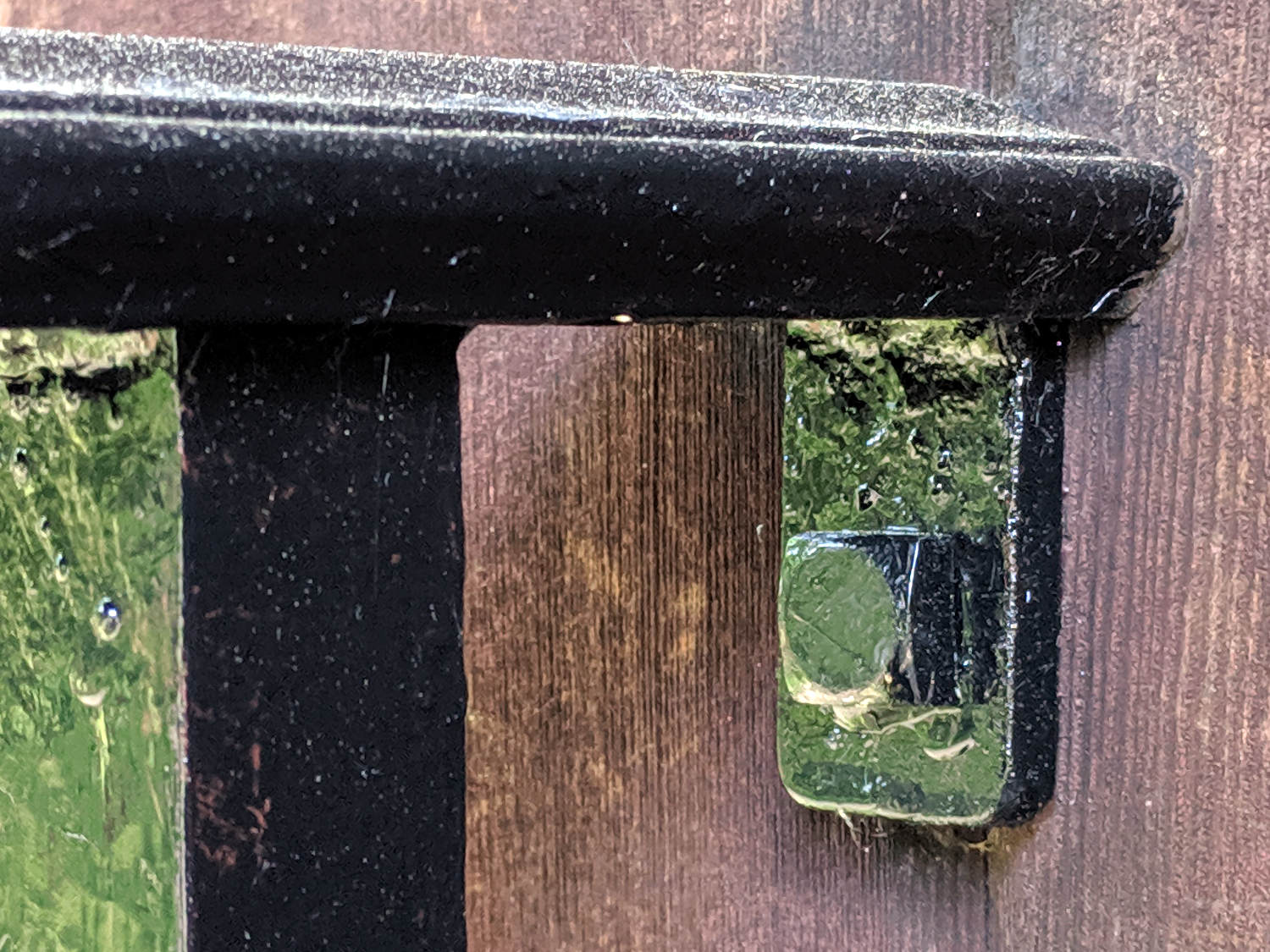
    Reassemble in reverse order and it’s all good:

    Bird feeder - perch installed
    Bird feeder – perch installed

    We’re supposed to bleach the feeder every week to kill off the bacteria causing House Finch Eye Disease and, while I can’t promise a weekly schedule, we’ll (try to) reduce the amount of crud on the feeder this year.

    If you’ve got a feeder, sign up for Project Feederwatch and do some citizen science!

  • Kenmore Progressive Vacuum Tool Adapters: Third Failure

    The adapter for an old Electrolux crevice tool (not the dust brush) snapped at the usual stress concentration after about three years:

    Crevice tool adapter - broken vs PVC pipe
    Crevice tool adapter – broken vs PVC pipe

    The lower adapter is the new version, made from a length of 1 inch PVC pipe (that’s the ID, kinda-sorta) epoxied into a revised Kenmore adapter fitting.

    The original OpenSCAD model provided the taper dimensions:

    Electrolux Crevice Tool Adapter - PVC taper doodles
    Electrolux Crevice Tool Adapter – PVC taper doodles

    The taper isn’t quite as critical as it seems, because the crevice tool is an ancient molded plastic part, but a smidge over half a degree seemed like a good target.

    Start by boring out the pipe ID until it’s Big Enough (or, equally, the walls aren’t Scary Thin) at 28 mm:

    Crevice tool adapter - boring PVC
    Crevice tool adapter – boring PVC

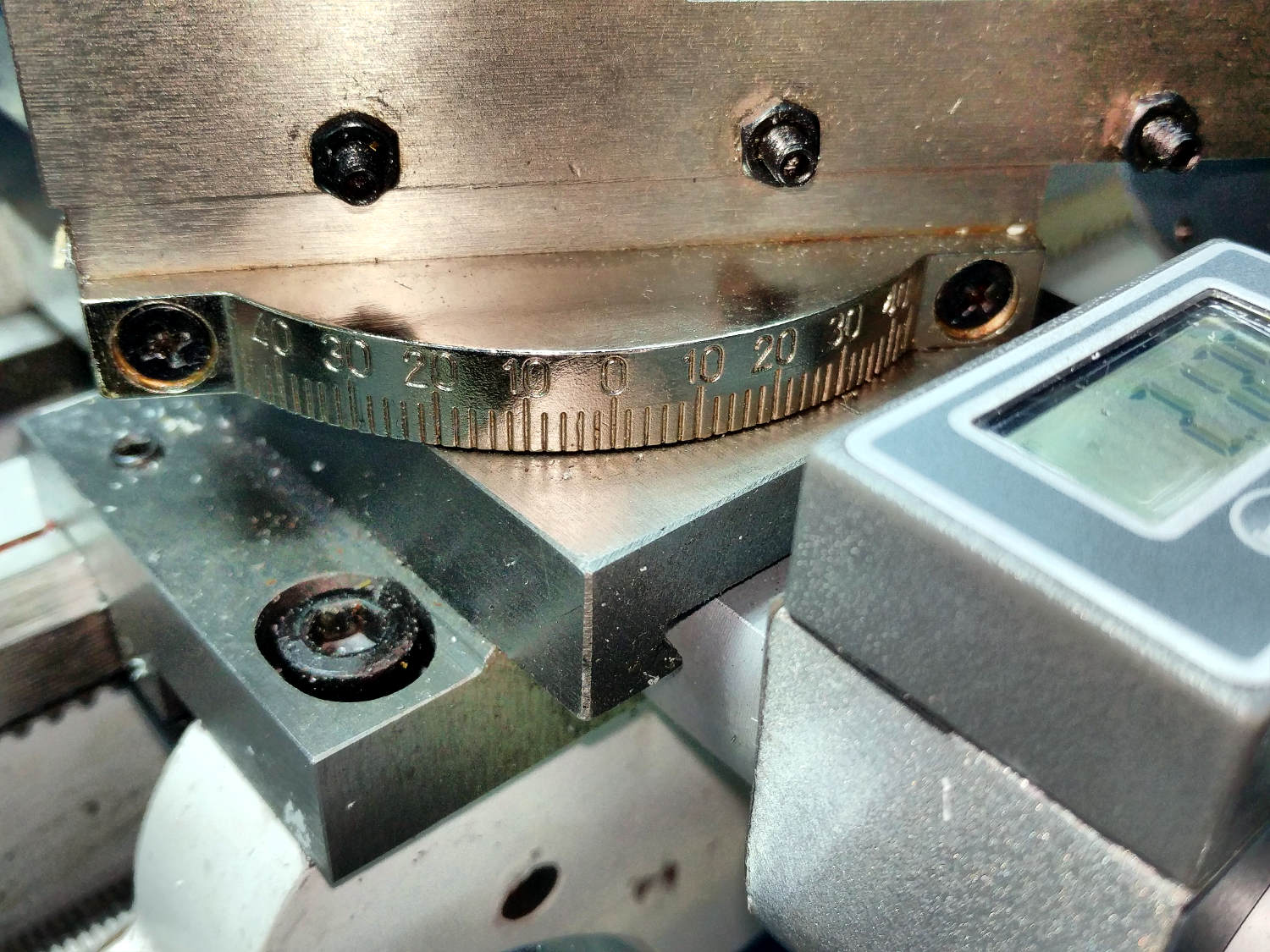
    Alas, the mini-lathe’s craptastic compound has 2° graduations:

    Minilathe compound angle scale
    Minilathe compound angle scale

    So I set the angle using a somewhat less craptastic protractor and angle gauge:

    Crevice tool adapter - compound angle
    Crevice tool adapter – compound angle

    The little wedge of daylight near the gauge pivot is the difference between the normal perpendicular-to-the-spindle axis setting and half-a-degree-ish.

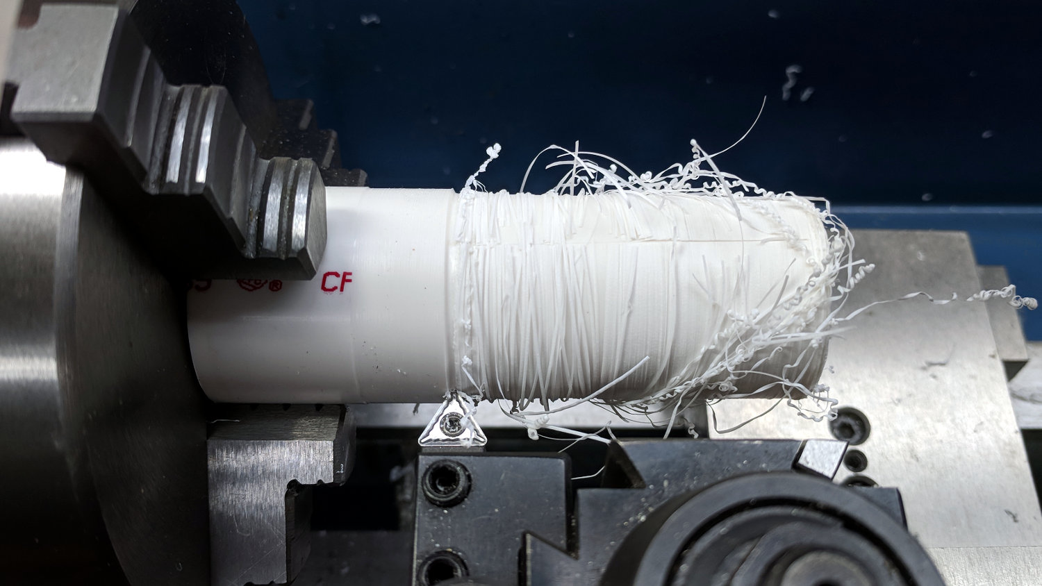
    Turning PVC produces remarkably tenacious swarf:

    Crevice tool adapter - PVC swarf
    Crevice tool adapter – PVC swarf

    The gash along the top comes from a utility knife; just pulling the swarf off didn’t work well at all.

    The column of figures down the right side of the doodles shows successive approximations to the target angle, mostly achieved by percussive adjustment, eventually converging to about the right taper with the proper dimensions.

    Cutting off the finished product with the (newly angled) cutoff bit:

    Crevice tool adapter - cutoff
    Crevice tool adapter – cutoff

    And then It Just Worked™.

    The OpenSCAD source code for all the adapters as a GitHub Gist:

    // Kenmore vacuum cleaner nozzle adapters
    // Ed Nisley KE4ZNU November 2015 and ongoing
    // Layout options
    Layout = "CrevicePipe"; // MaleFitting CoilWand FloorBrush
    // CreviceTool Crevice Pipe ScrubbyTool LuxBrush DustBrush
    //- Extrusion parameters must match reality!
    // Print with +1 shells and 3 solid layers
    ThreadThick = 0.25;
    ThreadWidth = 0.40;
    HoleWindage = 0.2;
    function IntegerMultiple(Size,Unit) = Unit * ceil(Size / Unit);
    Protrusion = 0.1; // make holes end cleanly
    //———————-
    // Dimensions
    ID1 = 0; // for tapered tubes
    ID2 = 1;
    OD1 = 2;
    OD2 = 3;
    LENGTH = 4;
    OEMTube = [35.0,35.0,41.7,40.5,30.0]; // main fitting tube
    EndStop = [OEMTube[ID1],OEMTube[ID2],47.5,47.5,6.5]; // flange at end of main tube
    FittingOAL = OEMTube[LENGTH] + EndStop[LENGTH];
    $fn = 12*4;
    //———————-
    // Useful routines
    module PolyCyl(Dia,Height,ForceSides=0) { // based on nophead's polyholes
    Sides = (ForceSides != 0) ? ForceSides : (ceil(Dia) + 2);
    FixDia = Dia / cos(180/Sides);
    cylinder(r=(FixDia + HoleWindage)/2,h=Height,$fn=Sides);
    }
    //——————-
    // Male fitting on end of Kenmore tools
    // This slides into the end of the handle or wand and latches firmly in place
    module MaleFitting() {
    Latch = [40,11.5,5.0]; // rectangle latch opening
    EntryAngle = 45; // latch entry ramp
    EntrySides = 16;
    EntryHeight = 15.0; // lower edge on *inside* of fitting
    KeyRadius = 1.0;
    translate([0,0,6.5])
    difference() {
    union() {
    cylinder(d1=OEMTube[OD1],d2=OEMTube[OD2],h=OEMTube[LENGTH]); // main tube
    hull() // insertion guide
    for (i=[-(6.0/2 – KeyRadius),(6.0/2 – KeyRadius)],
    j=[-(28.0/2 – KeyRadius),(28.0/2 – KeyRadius)],
    k=[-(26.0/2 – KeyRadius),(26.0/2 – KeyRadius)])
    translate([(i – (OEMTube[ID1]/2 + OEMTube[OD1]/2)/2 + 6.0/2),j,(k + 26.0/2 – 1.0)])
    sphere(r=KeyRadius,$fn=8);
    translate([0,0,-EndStop[LENGTH]]) // wand tube butts against this
    cylinder(d=EndStop[OD1],h=EndStop[LENGTH] + Protrusion);
    }
    translate([0,0,-OEMTube[LENGTH]]) // main bore
    cylinder(d=OEMTube[ID1],h=2*OEMTube[LENGTH] + 2*Protrusion);
    translate([0,-11.5/2,23.0 – 5.0]) // latch opening
    cube(Latch);
    translate([OEMTube[ID1]/2 + EntryHeight/tan(90-EntryAngle),0,0]) // latch ramp
    translate([(Latch[1]/cos(180/EntrySides))*cos(EntryAngle)/2,0,(Latch[1]/cos(180/EntrySides))*sin(EntryAngle)/2])
    rotate([0,-EntryAngle,0])
    intersection() {
    rotate(180/EntrySides)
    PolyCyl(Latch[1],Latch[0],EntrySides);
    translate([-(2*Latch[0])/2,0,-Protrusion])
    cube(2*Latch[0],center=true);
    }
    }
    }
    //——————-
    // Refrigerator evaporator coil wand
    module CoilWand() {
    union() {
    translate([0,0,50.0])
    rotate([180,0,0])
    difference() {
    cylinder(d1=EndStop[OD1],d2=42.0,h=50.0);
    translate([0,0,-Protrusion])
    cylinder(d1=35.0,d2=35.8,h=100);
    }
    translate([0,0,50.0 – Protrusion])
    MaleFitting();
    }
    }
    //——————-
    // Samsung floor brush
    module FloorBrush() {
    union() {
    translate([0,0,60.0])
    rotate([180,0,0])
    difference() {
    union() {
    cylinder(d1=EndStop[OD1],d2=32.4,h=10.0);
    translate([0,0,10.0 – Protrusion])
    cylinder(d1=32.4,d2=30.7,h=50.0 + Protrusion);
    }
    translate([0,0,-Protrusion])
    cylinder(d1=28.0,d2=24.0,h=100);
    }
    translate([0,0,60.0 – Protrusion])
    MaleFitting();
    }
    }
    //——————-
    // Crevice tool
    module CreviceTool() {
    union() {
    translate([0,0,60.0])
    rotate([180,0,0])
    difference() {
    union() {
    cylinder(d1=EndStop[OD1],d2=32.0,h=10.0);
    translate([0,0,10.0 – Protrusion])
    cylinder(d1=32.0,d2=30.4,h=50.0 + Protrusion);
    }
    translate([0,0,-Protrusion])
    cylinder(d1=28.0,d2=24.0,h=100);
    }
    translate([0,0,60.0 – Protrusion])
    MaleFitting();
    }
    }
    //——————-
    // Crevice tool
    // Hacked for 1 inch Schedule 40 PVC pipe stiffening tube
    module CrevicePipe() {
    PipeOD = 33.5;
    union() {
    translate([0,0,10.0])
    rotate([180,0,0])
    difference() {
    cylinder(d1=EndStop[OD1],d2=PipeOD+2*8*ThreadWidth,h=10.0);
    translate([0,0,-Protrusion])
    cylinder(d=PipeOD,h=100);
    }
    translate([0,0,10.0])
    MaleFitting();
    }
    }
    //——————-
    // Mystery brush
    module ScrubbyTool() {
    union() {
    translate([0,0,60.0])
    rotate([180,0,0])
    difference() {
    union() {
    cylinder(d1=EndStop[OD1],d2=31.8,h=10.0);
    translate([0,0,10.0 – Protrusion])
    cylinder(d1=31.8,d2=31.0,h=50.0 + Protrusion);
    }
    translate([0,0,-Protrusion])
    cylinder(d1=26.0,d2=24.0,h=100);
    }
    translate([0,0,60.0 – Protrusion])
    MaleFitting();
    }
    }
    //——————-
    // eBay horsehair dusting brush
    // Hacked for 3/4" Schedule 40 PVC stiffening tube
    // eBay: 30.0 32.0 30.0
    // Shopvac: 30.3 31.0 25.0
    // Must build snout down with brim to avoid support
    module DustBrush() {
    PipeOD = 27.0; // stiffening pipe
    Snout = [0,0, 31.0, 30.3, 25.0];
    TaperLength = 10.0; // transition cone from fitting to snout
    union() {
    translate([0,0,Snout[LENGTH] + TaperLength])
    rotate([180,0,0])
    difference() {
    union() {
    cylinder(d1=EndStop[OD1],d2=Snout[OD1],h=TaperLength);
    translate([0,0,TaperLength – Protrusion])
    cylinder(d1=Snout[OD1],d2=Snout[OD2],h=Snout[LENGTH] + Protrusion);
    }
    translate([0,0,-Protrusion]) // 3/4 inch Sch 40 PVC
    PolyCyl(PipeOD,100);
    }
    translate([0,0,Snout[LENGTH] + TaperLength – Protrusion])
    MaleFitting();
    }
    }
    //——————-
    // Electrolux brush ball
    module LuxBrush() {
    union() {
    translate([0,0,30.0])
    rotate([180,0,0])
    difference() {
    union() {
    cylinder(d1=EndStop[OD1],d2=30.8,h=10.0);
    translate([0,0,10.0 – Protrusion])
    cylinder(d1=30.8,d2=30.0,h=20.0 + Protrusion);
    }
    translate([0,0,-Protrusion])
    cylinder(d1=25.0,d2=23.0,h=30 + 2*Protrusion);
    }
    translate([0,0,30.0 – Protrusion])
    MaleFitting();
    }
    }
    //———————-
    // Build it!
    if (Layout == "MaleFitting")
    MaleFitting();
    if (Layout == "CoilWand")
    CoilWand();
    if (Layout == "FloorBrush")
    FloorBrush();
    if (Layout == "CreviceTool")
    CreviceTool();
    if (Layout == "CrevicePipe")
    CrevicePipe();
    if (Layout == "DustBrush")
    DustBrush();
    if (Layout == "ScrubbyTool")
    ScrubbyTool();
    if (Layout == "LuxBrush")
    LuxBrush();

  • Modifying a 2.5 mm Collet Pen Holder for a 3 mm Diamond Engraver

    Of course, the diamond engraving points have a 3 mm shaft that doesn’t fit in the 2.5 mm Collet Pen Holder, but making a hole bigger isn’t much of a problem …

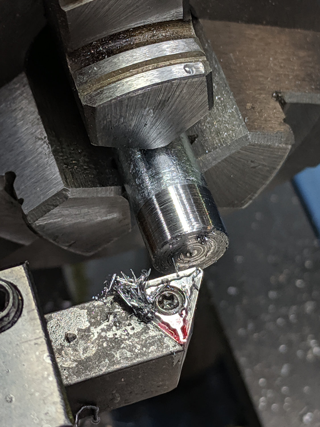
    Commence by drilling out the collet closer nut:

    Collet Holder - closer nut drilling
    Collet Holder – closer nut drilling

    The hole didn’t start out on center and I didn’t improve it in the least. A touch of the lathe bit and a little file work eased off the razor edge around the snout.

    The knurled ridges at the top are larger than the threaded body, which requires a shim around the threads to fit them into the lathe chuck. Start by cutting a slightly larger ID brass tube to the length of the threaded section:

    Collet Holder - brass shim cutoff
    Collet Holder – brass shim cutoff

    I finally got a Round Tuit and ground opposing angles on the cutoff tool ends, so I can choose which side of the cut goes through first. In this case, the left side cuts cleanly and the scrap end carries the thinned slot into the chip tray.

    Grab the tube in a pair of machinist vises and hacksaw a slot:

    Collet Holder - brass shim slitting
    Collet Holder – brass shim slitting

    Apply a nibbler to embiggen the slot enough to leave an opening when it’s squashed around the threads:

    Collet Holder - brass shim around threads
    Collet Holder – brass shim around threads

    Put a nut on the collet threads in an attempt to keep them neatly lined up while drilling:

    Collet Holder - collet drilling
    Collet Holder – collet drilling

    Drill the hole to a bit over 3 mm in small steps, because it’s not the most stable setup you’ve ever used. Eventually, the diamond point just slips right in:

    Collet Holder - 3 mm scribe test fit
    Collet Holder – 3 mm scribe test fit

    Reassemble in reverse order and It Just Works:

    Collet Holder - finished
    Collet Holder – finished

    Now, to scratch up some acrylic!

  • Cheese Slicer Rebuild

    Cheese Slicer Rebuild

    The cheese slicer frame looked much better after sandblasting with 220 aluminum oxide grit:

    Cheese slicer - sandblasted
    Cheese slicer – sandblasted

    The flower bed outside the Basement Laboratory door seems a bit dusty, though.

    Slathering it with JB Weld steel-filled epoxy went reasonably well:

    Cheese slicer - JB Weld curing
    Cheese slicer – JB Weld curing

    JB Weld is much much more viscous than the clear XTC-3D I used last year and the final coating, while smoother than what you see here, has too many sags and dents to say “good job”. I didn’t bother coating the upper tips, because the epoxy will wear off from my morning KP.

    The aluminum roller turned on those bare stainless steel screws in the tray, with the threads chewing into the roller bore. While the epoxy was curing, I drilled out the roller to remove most of the ridges:

    Cheese slicer - drilling roller
    Cheese slicer – drilling roller

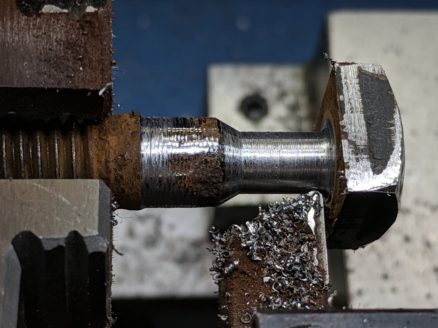
    Cut a pair of stainless screws slightly longer than the old screws, then turn the threads off to make a shaft:

    Cheese slicer - screw reshaping
    Cheese slicer – screw reshaping

    The lathe spindle runs in reverse, so the cutting force tends to tighten the screw in the nuts. The big old South Bend lathe had a screw-on chuck and didn’t really like turning backwards.

    The new screws won’t win any beauty prizes, but they get the job done:

    Cheese slicer - screw shafts
    Cheese slicer – screw shafts

    Turn a Delrin rod to a press fit in the drilled-out roller:

    Cheese slicer - turning Delrin bearing
    Cheese slicer – turning Delrin bearing

    Part it off, repeat, ram them into the roller, then drill to a loose fit around the smooth-ish screw shafts:

    Cheese slicer - drilling Delrin bearing
    Cheese slicer – drilling Delrin bearing

    Reassemble in reverse order:

    Cheese slicer - rebuilt
    Cheese slicer – rebuilt

    Looks downright industrial, it does.

    Stipulated: this makes no economic sense, absent the simple fact we appreciate utensils that just work.