The Smell of Molten Projects in the Morning

Ed Nisley's Blog: Shop notes, electronics, firmware, machinery, 3D printing, laser cuttery, and curiosities. Contents: 100% human thinking, 0% AI slop.

Tag: Mini-lathe

Tweaking an LMS 5200 Mini-Lathe

  • Shower Curtain Magnet Anchors

    Back in the day, bathtubs had a porcelain coating over a cast-iron carcass, so embedding little magnets in shower curtains worked perfectly to keep the loose ends from billowing out of the tub. Surprisingly, even here in the future, with plastic bathtubs ruling the land, some shower curtains still have magnets. The mud-job tile walls of shower stall in the Black Bathroom have nary a trace of iron, but we though I could add ferrous targets for a new shower curtain, thusly:

    Shower Curtain Anchor - installed
    Shower Curtain Anchor – installed

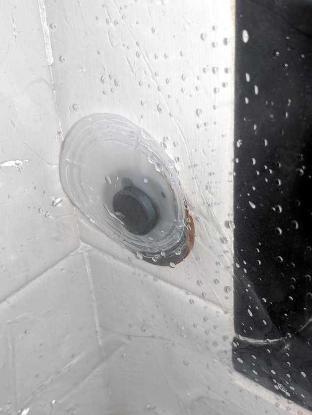
    The magnet lives inside a heat-sealed disk, so it’s (more-or-less) isolated from the water. As you’d expect, it’s a cheap ceramic magnet, not a high-performance neodymium super magnet, with no more strength than absolutely necessary to work under the most ideal of conditions.

    My anchors must also be waterproof, firmly attached, non-marking, easily removable, and no more ugly than absolutely necessary. The general idea is to slice the bottom from a pill bottle, entomb a thin steel disk in epoxy, and attach to the tile with a patch of outdoor-rated foam tape.

    So, we begin …

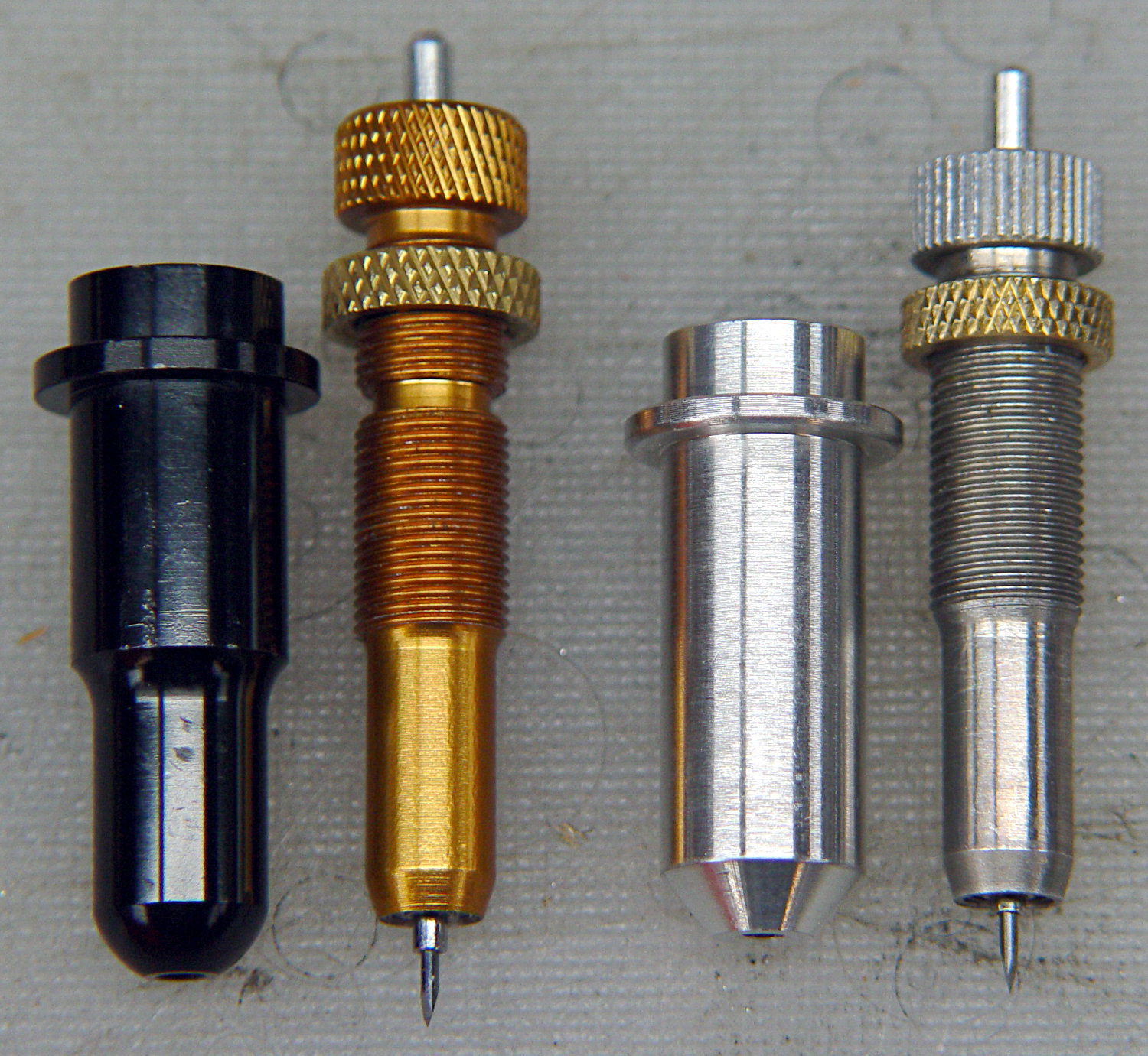
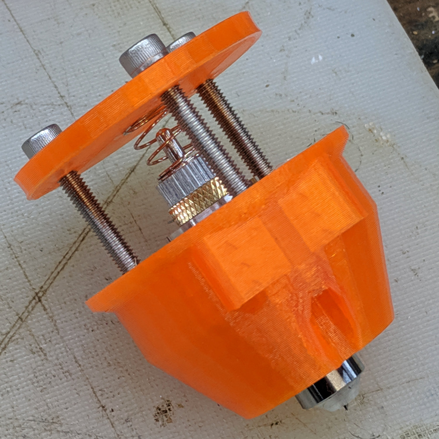
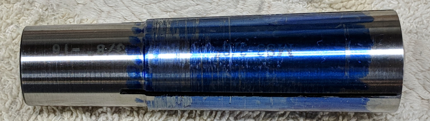
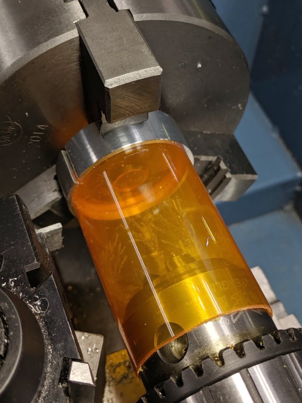
    Cutting a narrow ring from a pill bottle requires a collet around the whole circumference, which started life as some sort of stout aluminum pole:

    Shower Curtain Anchor - cutting tube stock
    Shower Curtain Anchor – cutting tube stock

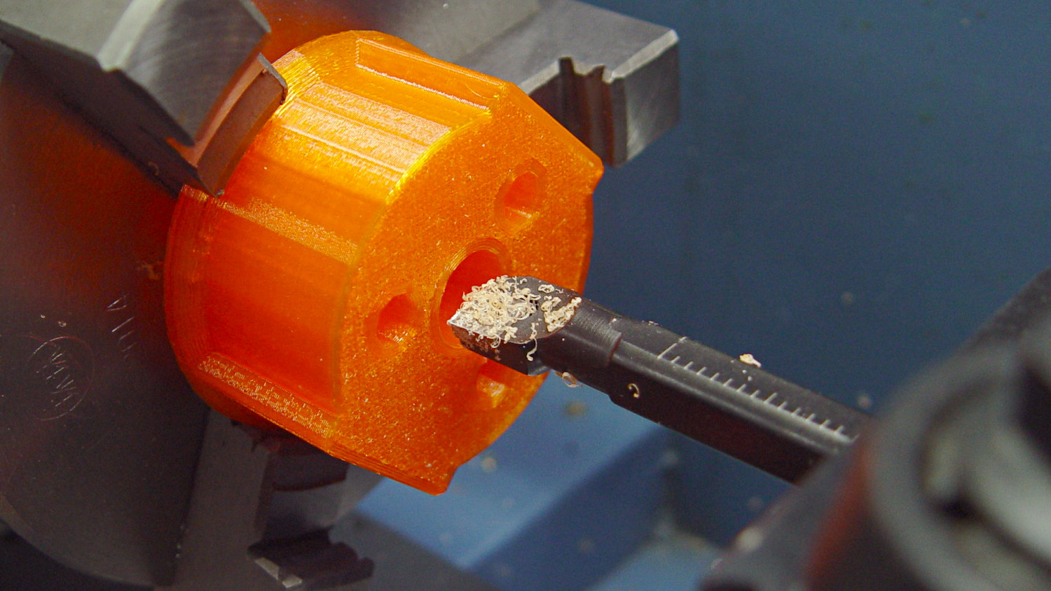
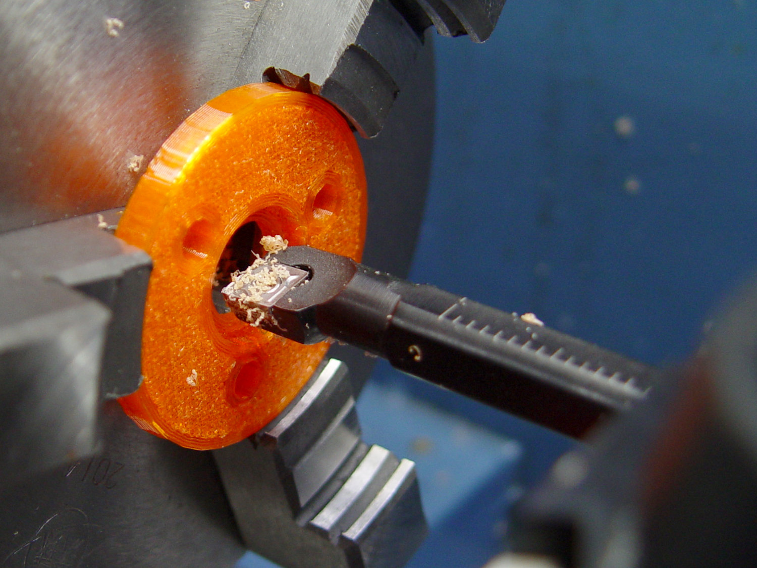
    Bore out the inside, with a small step to locate the bottle:

    Shower Curtain Anchor - boring fixture
    Shower Curtain Anchor – boring fixture

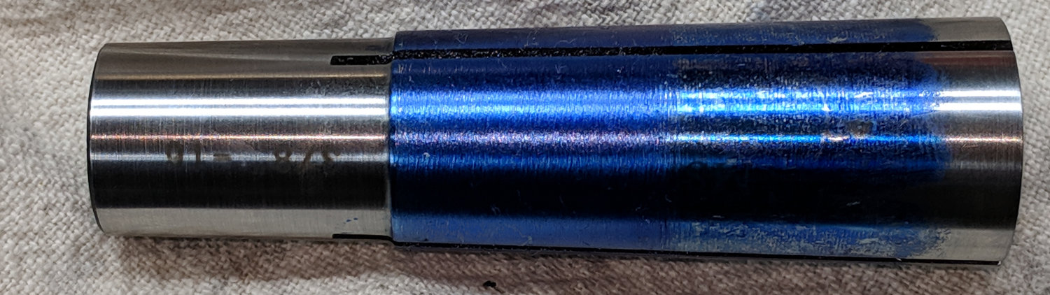
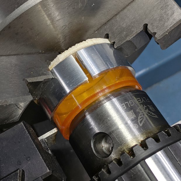
    Clean up the outside, just for pretty:

    Shower Curtain Anchor - turning fixture OD
    Shower Curtain Anchor – turning fixture OD

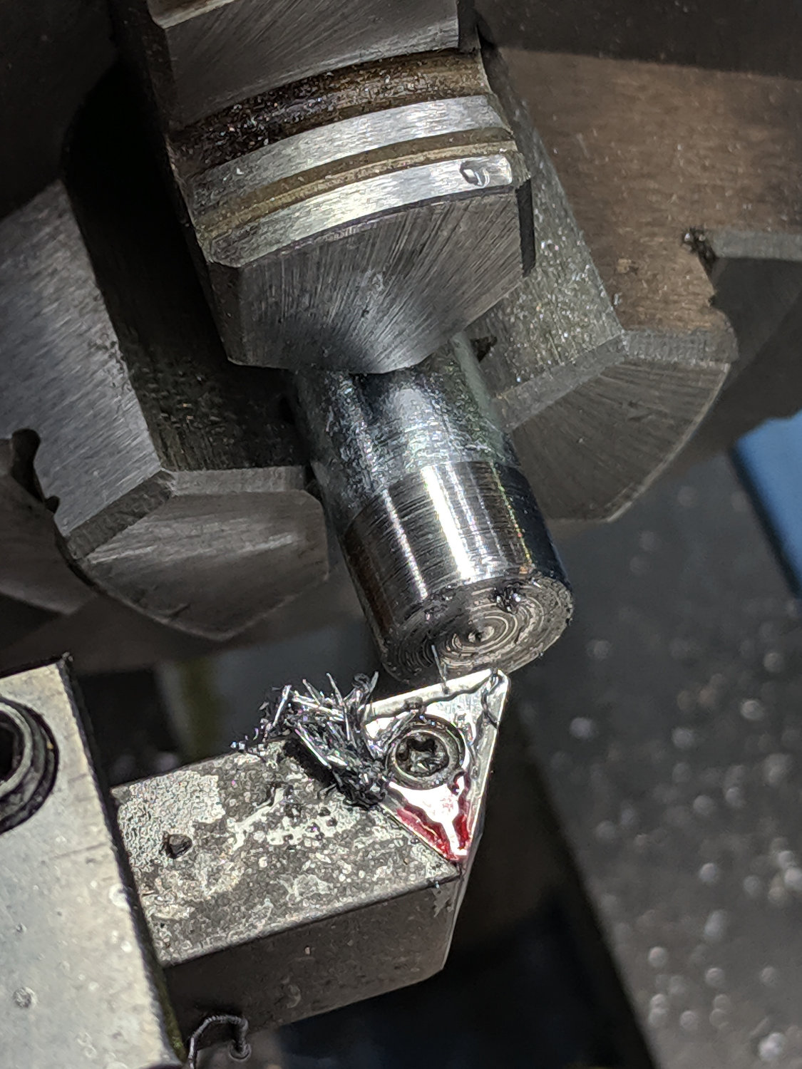
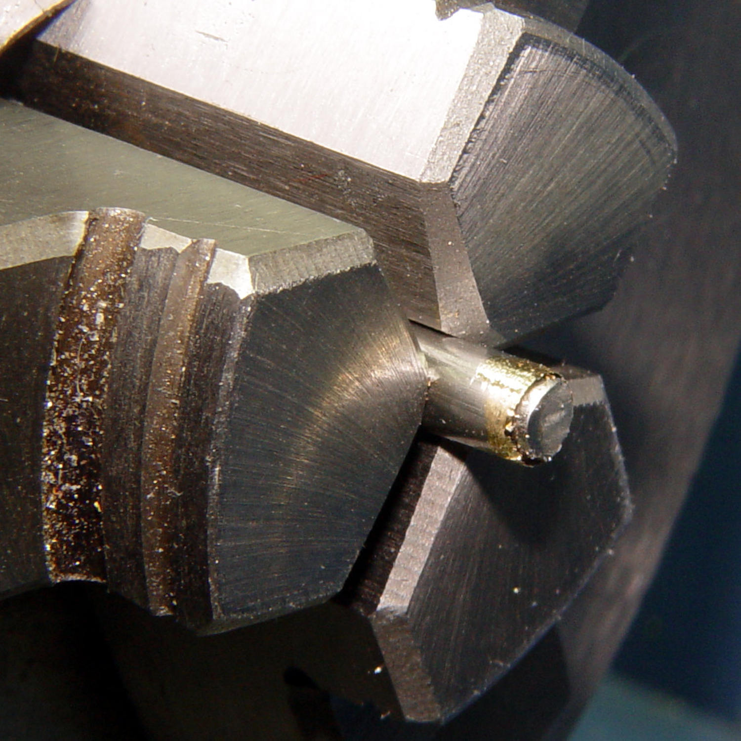
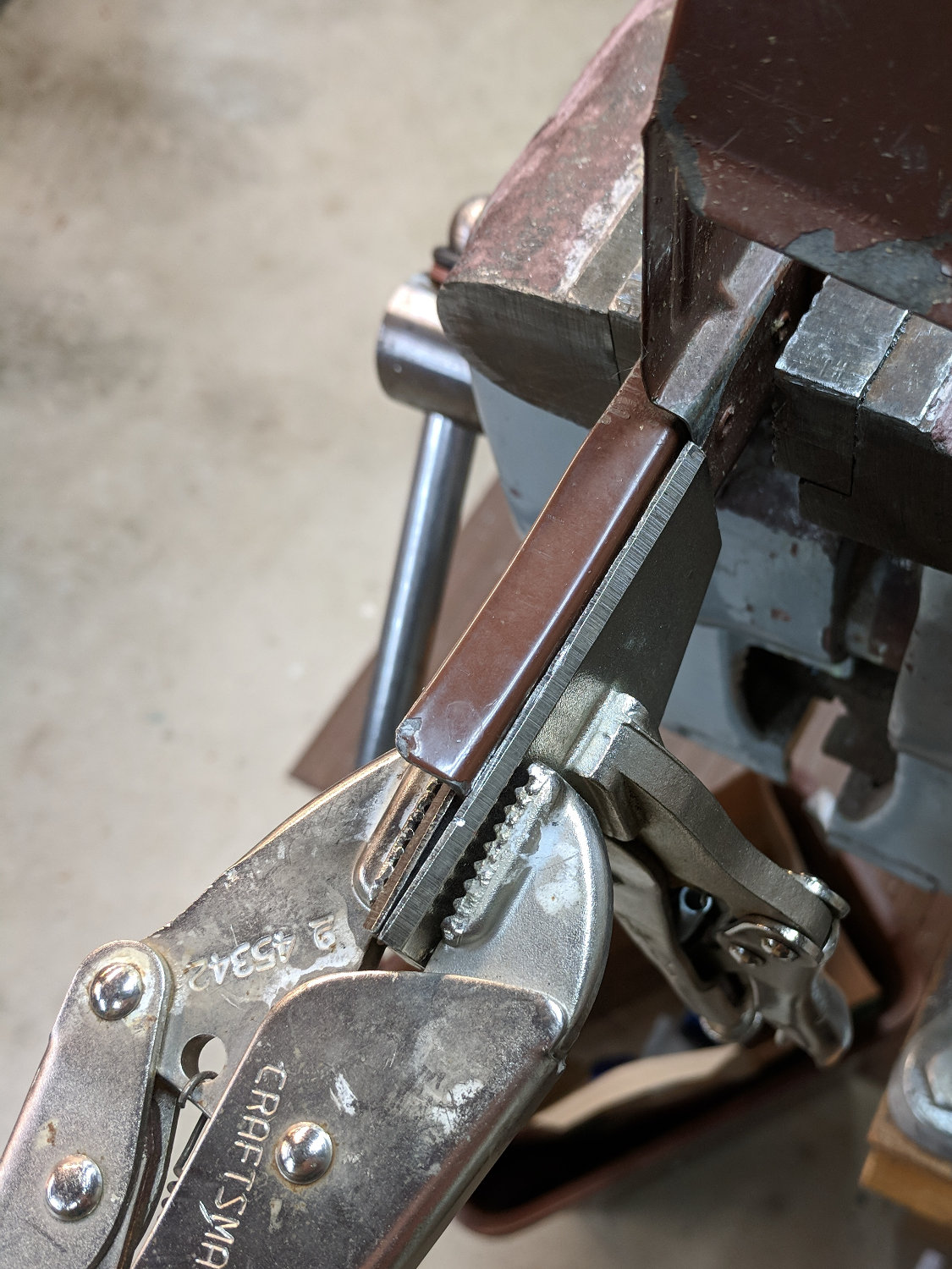
    Slit the fixture to let it collapse around the bottle, then chuck up the first victim with support from a conveniently sized drill chuck in the tailstock:

    Shower Curtain Anchor - cutting bottle
    Shower Curtain Anchor – cutting bottle

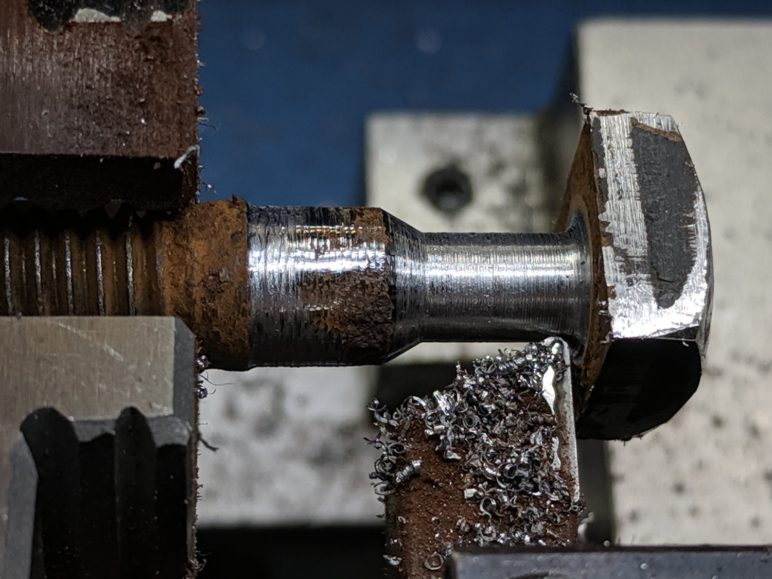
    I did a better job of cutting the second bottle to the proper length:

    Shower Curtain Anchor - parting base
    Shower Curtain Anchor – parting base

    Nibble disks from sheet metal, half-fill the bottle bottoms with steel-filled (and, thus, magnetic!) JB Weld epoxy, insert disks, add sufficient epoxy to cover the evidence:

    Shower Curtain Anchor - epoxy curing
    Shower Curtain Anchor – epoxy curing

    Fast-forward to the next day, punch out two disks of double-sided foam tape:

    Shower Curtain Anchor - adhesive foam
    Shower Curtain Anchor – adhesive foam

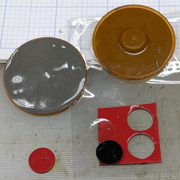
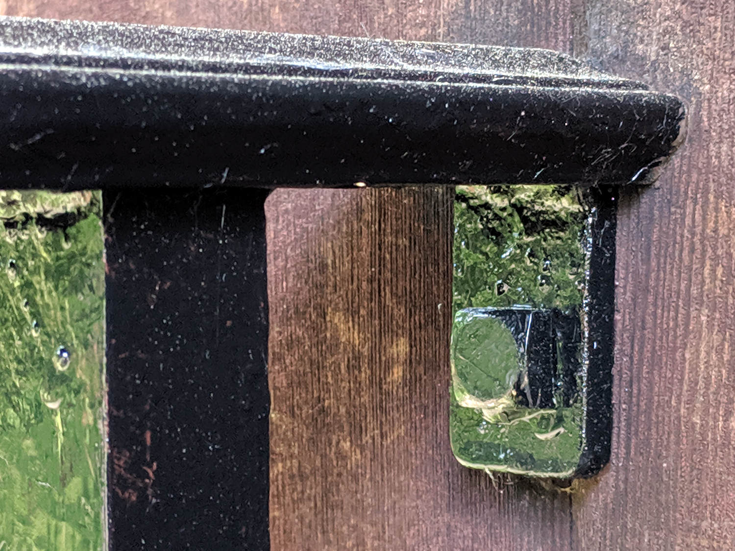
    Affix, install, and it’s all good.

    Actually, it’s not. The ceramic magnets are so weak they don’t hold the curtain nearly well enough to satisfy me. The next anchor iteration should have embedded neodymium magnets to attract the curtain’s crappy ceramic magnets, but this is Good Enough™ for now.

  • Primitive Screwheads

    Painting the patio railing required removing the short section on the garage, which stalled with a thoroughly galled / corroded nut on the 2 inch bolt going through the wall. Deploying a Dremel slitting wheel and bashing the slit open with a cold chisel saved the day, as shown in this staged reenactment:

    Patio railing - square head bolt - extraction
    Patio railing – square head bolt – extraction

    It seems square head bolts have gone out of fashion, at least in the 3/8-16 size seen here, over the last half century:

    Patio railing - square head bolts
    Patio railing – square head bolts

    I reused the lag screw with no qualms at all.

    The local fastener emporium had square bolts ranging upward from 3/4-10, which wasn’t much help. Amazon has ’em, if you spend enough time rummaging around in the debris from its search engine, at a buck apiece in lots of ten. Fortunately, a local big-box home repair store had 3/8-16 hex head steel bolts and square nuts, so I needn’t start from scratch.

    Start by turning off the hex head:

    Patio railing - square head bolt - removing hex head
    Patio railing – square head bolt – removing hex head

    Thread the end, starting in the lathe and ending with a die turned just barely enough to accept the nut:

    Patio railing - square head bolt - threading
    Patio railing – square head bolt – threading

    Epoxy the nut in place and sand it to rough up the surface finish enough to hold the primer:

    Patio railing - square head bolt - lineup
    Patio railing – square head bolt – lineup

    Yeah, that’s a nasty little zit. Fortunately, nobody will ever notice.

    Prime & paint the railing, affix it to the garage wall, then prime & paint the bolt:

    Patio railing - square head bolt - installed
    Patio railing – square head bolt – installed

    Thing looks like it grew there; tell nobody about the zit.

    The yellow blotches decorating the shiny black paint come from the pine trees across the driveway. The first day of pine pollen season corresponded to the second day I intended to paint; the dust clouds were a wonder to behold.

    Bonus Quality Shop Time!

    The far end of the railing around the patio has a bracket against the house siding with a hole intended for a 1/4 inch bolt they never installed, perhaps because there’s no way to maneuver a bolt into the space available.

    The threads on the 3/8-16 bolt may be wrecked, but turning the shank down to 1/4 inch isn’t any big deal:

    Patio railing - fake bolt - thinning shank
    Patio railing – fake bolt – thinning shank

    Part off the head with a stub just long enough to fit into the bracket, epoxy that sucker into the hole, and paint it black:

    Patio railing - fake bolt - installed
    Patio railing – fake bolt – installed

    The square post on the left goes down to an anchor in the concrete patio, the railing is welded to a 4 inch column a foot away, and the end of the railing isn’t going anywhere; the fake bolt is purely for show.

    And, yes, the dust atop the railing is more pollen from the pine trees responsible for the weird green-yellow reflections on the vertical surfaces.

    No boomstick required!

  • MPCNC Drag Knife: Ground Shaft in LM12UU Bearing

    The 12 mm drag knife holder on the left slides nicely in an LM12UU bearing:

    Drag Knife holders - detail
    Drag Knife holders – detail

    However, its aluminum body isn’t really intended as a bearing surface and it extends only halfway through the LM12UU, so I finally got around to modifying the 11.5 mm body on the right to fit into a section of 12 mm ground shaft:

    Drag Knife - turning 11.5 mm body to 10 mm
    Drag Knife – turning 11.5 mm body to 10 mm

    The general idea is to turn the body down to 10 mm OD; the picture shows the first pass over the nose after turning the far end down and removing the flange in the process. Exact concentricity of both ends isn’t important (it gets epoxied into a 10 mm hole through the 12 mm ground shaft), but it came out rather pretty:

    Drag Knife - 11.5 mm body - turned to 10 mm
    Drag Knife – 11.5 mm body – turned to 10 mm

    The ground shaft started as a pen holder:

    DW660 Pen Holder - ground shaft
    DW660 Pen Holder – ground shaft

    I knocked off the ring and bored the interior to fit the 10 mm knife body. The large end of the existing bore came from a 25/64 inch = 9.92 mm drill, so it was just shy of 10.0 mm, and I drilled the small end upward from 0.33 inch = 8.4 mm.

    The smallest trio of a new set of cheap carbide boring bars allegedly went into a 5/16 inch = 7.9 mm bore, but I had to file the bar body down and diamond-file more end relief into the carbide for clearance inside the drilled hole:

    Modified boring bar vs original
    Modified boring bar vs original

    I blued the bit, kissed it against the drilled bore, filed off whatever wasn’t blued, and iterated until the carbide edge started cutting. Sissy cuts all the way, with no pix to show for all the flailing around.

    Epoxying the turned-down drag knife body into the shaft: anticlimactic.

    The solid model features a stylin’ tapered snout:

    Drag Knife LM12UU holder - tapered end
    Drag Knife LM12UU holder – tapered end

    Which gets an LM12UU bearing rammed into place:

    Drag Knife - LM12UU holder - inserting bearing
    Drag Knife – LM12UU holder – inserting bearing

    The steel block leaves the bearing flush with the plastic surface, rather than having it continue onward and indent itself into the wood; I can learn from my mistakes.

    The new idea: a single spring pressing the knife holder downward, reacting against a fixed plastic plate:

    Drag Knife - LM12UU ground shaft - assembled
    Drag Knife – LM12UU ground shaft – assembled

    Unlike the previous design, the upper plate doesn’t move, so there’s no problem caused by sliding along the screw threads. I should run nylock nuts up against the plate to keep it in place, stiffen the structure, and provide some friction to keep the screws from loosening.

    The top of the knife holder now has a boss anchoring the spring:

    Drag Knife - turning spring recess
    Drag Knife – turning spring recess

    As you’d expect, the ground shaft slides wonderfully in the bearing, because that’s what it’s designed to do, and the knife has essentially zero stiction and friction at any point along the bearing, which is exactly what I wanted.

    The spring, from the same assortment as all the others, has a 48 g/mm rate.

    The OpenSCAD source code as a GitHub Gist:

    // Drag Knife Holder using LM12UU linear bearing
    // Ed Nisley KE4ZNU – 2019-04-26
    // 2019-06-01 Taper the nose
    Layout = "Build"; // [Build, Show, Puck, Mount, Plate]
    /* [Extrusion] */
    ThreadThick = 0.25; // [0.20, 0.25]
    ThreadWidth = 0.40; // [0.40]
    /* [Hidden] */
    Protrusion = 0.1; // [0.01, 0.1]
    HoleWindage = 0.2;
    inch = 25.4;
    function IntegerMultiple(Size,Unit) = Unit * ceil(Size / Unit);
    ID = 0;
    OD = 1;
    LENGTH = 2;
    //- Adjust hole diameter to make the size come out right
    module PolyCyl(Dia,Height,ForceSides=0) { // based on nophead's polyholes
    Sides = (ForceSides != 0) ? ForceSides : (ceil(Dia) + 2);
    FixDia = Dia / cos(180/Sides);
    cylinder(r=(FixDia + HoleWindage)/2,h=Height,$fn=Sides);
    }
    //- Dimensions
    // Basic shape of DW660 snout fitting into the holder
    // Lip goes upward to lock into MPCNC mount
    Snout = [44.6,50.0,9.6]; // LENGTH = ID height
    Lip = 4.0; // height of lip at end of snout
    // Knife holder & suchlike
    KnifeBody = [12.0,18.0,2.0]; // body OD, flange OD, flange thickness
    Spring = [9.5,10.0,3*ThreadThick]; // compression spring loading knife blade
    PinAccess = 4.0; // hole to reach knife ejection pin
    WallThick = 4.0; // minimum thickness / width
    Screw = [4.0,8.5,25.0]; // thread ID, washer OD, length
    Insert = [4.0,6.0,10.0]; // brass insert
    Bearing = [12.0,21.0,30.0]; // linear bearing body
    Plate = [PinAccess,Snout[OD] – WallThick,WallThick]; // spring reaction plate
    echo(str("Plate: ",Plate));
    SpringSeat = [0.56,7.2,2*ThreadThick]; // wire = ID, coil = OD, seat depth = length
    PuckOAL = max(Bearing[LENGTH],(Snout[LENGTH] + Lip)); // total height of DW660 fitting
    echo(str("PuckOAL: ",PuckOAL));
    Key = [Snout[ID],25.7,(Snout[LENGTH] + Lip)]; // rectangular key
    NumScrews = 3;
    //ScrewBCD = 2.0*(Bearing[OD]/2 + Insert[OD]/2 + WallThick);
    ScrewBCD = (Snout[ID] + Bearing[OD])/2;
    NumSides = 9*4; // cylinder facets (multiple of 3 for lathe trimming)
    module DW660Puck() {
    translate([0,0,PuckOAL])
    rotate([180,0,0]) {
    cylinder(d=Snout[OD],h=Lip/2,$fn=NumSides);
    translate([0,0,Lip/2])
    cylinder(d1=Snout[OD],d2=Snout[ID],h=Lip/2,$fn=NumSides);
    cylinder(d=Snout[ID],h=(Snout[LENGTH] + Lip),$fn=NumSides);
    translate([0,0,(Snout[LENGTH] + Lip) – Protrusion])
    cylinder(d1=Snout[ID],d2=2*WallThick + Bearing[OD],h=PuckOAL – (Snout[LENGTH] + Lip),$fn=NumSides);
    intersection() {
    translate([0,0,0*Lip + Key.z/2])
    cube(Key,center=true);
    cylinder(d=Snout[OD],h=Lip + Key.z,$fn=NumSides);
    }
    }
    }
    module MountBase() {
    difference() {
    DW660Puck();
    translate([0,0,-Protrusion]) // bearing
    PolyCyl(Bearing[OD],2*PuckOAL,NumSides);
    for (i=[0:NumScrews – 1]) // clamp screws
    rotate(i*360/NumScrews)
    translate([ScrewBCD/2,0,-Protrusion])
    rotate(180/8)
    PolyCyl(Insert[OD],2*PuckOAL,8);
    }
    }
    module SpringPlate() {
    difference() {
    cylinder(d=Plate[OD],h=Plate[LENGTH],$fn=NumSides);
    translate([0,0,-Protrusion]) // ejection pin hole
    PolyCyl(PinAccess,2*Plate[LENGTH],NumSides);
    translate([0,0,Plate[LENGTH] – Spring[LENGTH]]) // spring retaining recess
    PolyCyl(Spring[OD],Spring[LENGTH] + Protrusion,NumSides);
    for (i=[0:NumScrews – 1]) // clamp screws
    rotate(i*360/NumScrews)
    translate([ScrewBCD/2,0,-Protrusion])
    rotate(180/8)
    PolyCyl(Screw[ID],2*PuckOAL,8);
    if (false)
    for (i=[0:NumScrews – 1]) // coil positioning recess
    rotate(i*360/NumScrews)
    translate([ScrewBCD/2,0,-Protrusion])
    rotate(180/8)
    PolyCyl(SpringSeat[OD],SpringSeat[LENGTH] + Protrusion,8);
    }
    }
    //—–
    // Build it
    if (Layout == "Puck")
    DW660Puck();
    if (Layout == "Plate")
    SpringPlate();
    if (Layout == "Mount")
    MountBase();
    if (Layout == "Show") {
    MountBase();
    translate([0,0,1.6*PuckOAL])
    rotate([180,0,0])
    SpringPlate();
    }
    if (Layout == "Build") {
    translate([0,Snout[OD]/2,PuckOAL])
    rotate([180,0,0])
    MountBase();
    translate([0,-Snout[OD]/2,0])
    SpringPlate();
    }

  • MPCNC Drag Knife: PETG Linear Bearing

    Having reasonable success using a 12 mm hole bored in a 3D printed mount for the nice drag knife holder on the left, I thought I’d try the same trick for the raw aluminum holder on the right side:

    Drag Knife holders - detail
    Drag Knife holders – detail

    The 11.5 mm body is long enough to justify making a longer holder with more bearing surface:

    Drag Knife Holder - 11.5 mm body - Slic3r preview
    Drag Knife Holder – 11.5 mm body – Slic3r preview

    Slicing with four perimeter threads lays down enough reasonably solid plastic to bore the central hole to a nice sliding fit:

    Drag Knife - 11.5 mm body - boring
    Drag Knife – 11.5 mm body – boring

    The top disk gets bored to a snug press fit around the flange and upper body:

    Drag Knife - 11.5 mm body - flange boring
    Drag Knife – 11.5 mm body – flange boring

    Assemble with springs and it pretty much works:

    Drag Knife - hexagon depth setting
    Drag Knife – hexagon depth setting

    Unfortunately, it doesn’t work particularly well, because the two screws tightening the MPCNC’s DW660 tool holder (the black band) can apply enough force to deform the PETG mount and lock the drag knife body in the bore, while not being quite tight enough to prevent the mount from moving.

    I think the holder for the black knife (on the left) worked better, because:

    • The anodized surface is much smoother & slipperier
    • The body is shorter, so less friction

    In any event, I reached a sufficiently happy compromise for some heavy paper / light cardboard test shapes, but a PETG bearing won’t suffice for dependable drag knife cuttery.

    Back to the laboratory …

  • Improved Shoelace Ferrule Aglets

    After considerable evaluation, the Customer decided the shoelaces were still too long and said the hex-crimped ferrules were entirely too rough and tended to snag on things. This time, I prepared the ferrules by chucking them in the lathe:

    Ferrule - original flange
    Ferrule – original flange

    The steel rod inside the ferrule encourages it to remain round and not collapse while I’m filing off the flange that normally holds the plastic strain-relief doodad:

    Ferrule - reshaped flange
    Ferrule – reshaped flange

    I snipped another half inch off each end of the laces and crimped on the prepared ferrules:

    Shoelace ferrule aglets
    Shoelace ferrule aglets

    Which were definitely too jaggy, so they now sport an epoxy coat:

    Ferrule aglets - epoxy coat
    Ferrule aglets – epoxy coat

    Alas, JB Kwik epoxy has a pot life measured in minutes, so the last ferrule looks a bit lumpy. They seem to work fine and the Customer is happy with the results.

    Memo to Self: Next time, dunk the ferrules in a pot of slow-curing JB Weld and let them drain overnight.

  • Minilathe MT3 Spindle Collet Fitting

    I’ve used the LMS set of inch-size MT3 spindle collets on occasion, but releasing them required an unseemly amount of drawbar battering. It recently occurred to me to check their fit in the spindle taper:

    Minilathe - MT3 collet - taper test
    Minilathe – MT3 collet – taper test

    Huh.

    The only place they touch the spindle is right around the base, so it’s no wonder they clamp poorly and release grudgingly. I tried several others with the same result.

    Cross-checking shows a much closer fit along the entire length of the dead center, so it’s not the spindle’s fault:

    Minilathe - Dead Center - MT3 taper check
    Minilathe – Dead Center – MT3 taper check

    Stipulated: we’re not talking toolroom precision here

    I set the collets on centers:

    Minilathe - MT3 collet - drive setup
    Minilathe – MT3 collet – drive setup

    And proceeded to file away the offending section to move the clamping force closer to the business end of the collet:

    Minilathe - MT3 collet - filed result
    Minilathe – MT3 collet – filed result

    I did the small collets, the ones I’m most likely to need, and left the big ones for another rainy day.

    They don’t have much clamping range and seem good only for exact-inch-size rods.

    I should lay in a stock of ER16 and maybe ER32 collets for small stuff.


  • Bird Feeder Unbending

    At some point in its history, the left rail holding the wood perch on our industrial-strength “squirrel proof” seed feeder took a hit, most likely from being dropped:

    Squirrel on bird feeder
    Squirrel on bird feeder

    I finally got a Round Tuit and un-bent the poor thing:

    Bird feeder - rail un-bending
    Bird feeder – rail un-bending

    Because the bend happened at the base of the vertical strut holding the shutter, I clamped a Genuine Vise-Grip sheet metal pliers along the straight section. The Craftsman knock-off Vise-Grip then applied torque at the bend, rather than just making things worse, and some two-axis tweakage lined up the rail pretty well.

    With the bend taken care of, I clamped the rail in the bench vise with some scrap wood around the strut:

    Bird feeder - warped rail
    Bird feeder – warped rail

    A percussive adjustment jam session flattened the top flange, leaving both sections as flat as they’re gonna get.

    While I was at it, I turned a pair of stepped aluminum washers for the new wood rod:

    Bird feeder - parting off washer
    Bird feeder – parting off washer

    Which looked about like you’d expect, including a little chatter from the cut off tool:

    Bird feeder - perch hardware
    Bird feeder – perch hardware

    Yeah, I drilled the wood rod on the lathe, too; I loves me some simple lathe action.

    Reassemble in reverse order and it’s all good:

    Bird feeder - perch installed
    Bird feeder – perch installed

    We’re supposed to bleach the feeder every week to kill off the bacteria causing House Finch Eye Disease and, while I can’t promise a weekly schedule, we’ll (try to) reduce the amount of crud on the feeder this year.

    If you’ve got a feeder, sign up for Project Feederwatch and do some citizen science!