Ed Nisley's Blog: Shop notes, electronics, firmware, machinery, 3D printing, laser cuttery, and curiosities. Contents: 100% human thinking, 0% AI slop.
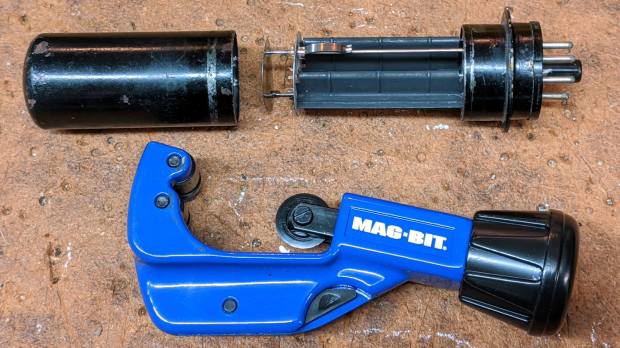
I’ve always wondered what’s inside a metal-case vacuum tube:
Dual rectifier tube 5T4 – metal case opened
The cutter last saw action on the EMT used in the MPCNC, so it’s intended for use on steel tubes. I thought about parting the case off in the lathe, but a tubing cutter sufficed for a first attempt, even if it couldn’t cut quite as close to the flange as I wanted.
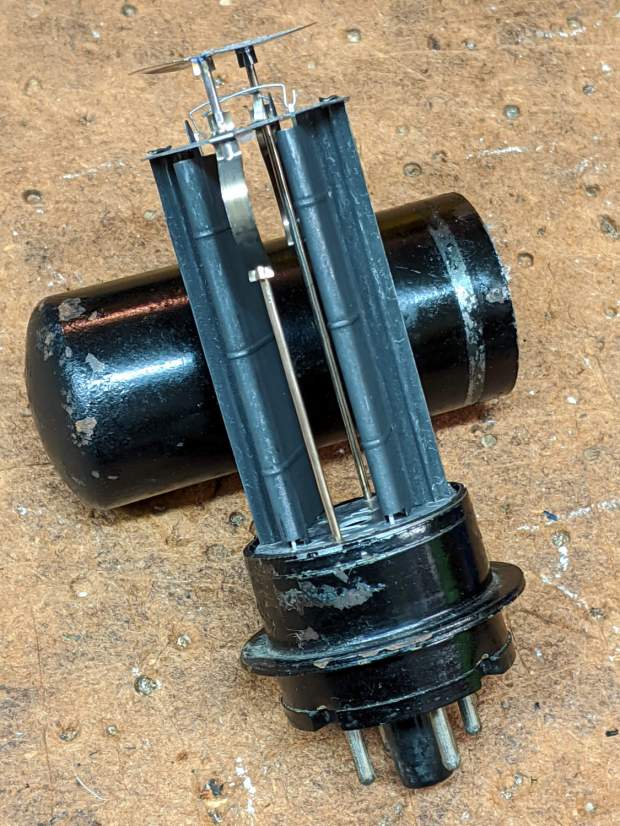
A 5T4 tube is a full-wave rectifier with two sections:
Dual rectifier tube 5T4 – upright
Unsurprisingly, the guts resemble those of glass-envelope rectifier tubes in my collection, like this 5U4GB:
5U4GB Full-wave vacuum rectifier – cyan red phase
The metal case would be far more rugged than a glass bottle and, perhaps, the flange locked the tube into its socket against vibration.
The filaments surely weren’t thoriated, so it’s all good …
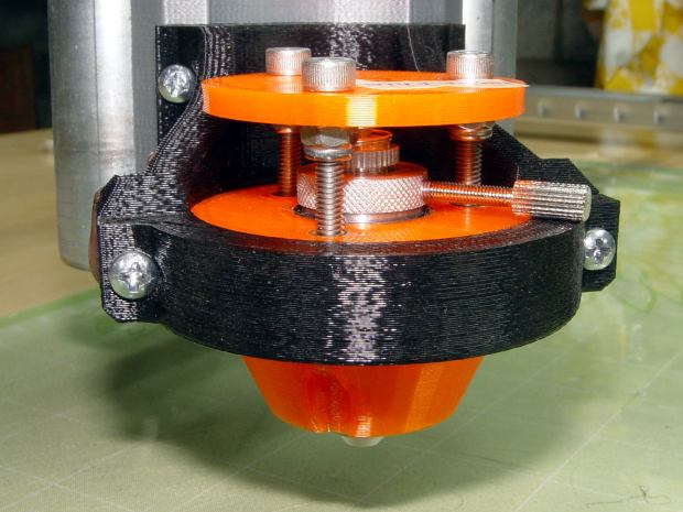
This happened a few times before, because my fingers don’t fit neatly inside the drag knife holder to tighten the lock ring:
Drag Knife – LM12UU ground shaft – assembled
[Update: The lock ring keeps the holder at a fixed position inside the 12 mm shaft and doesn’t affect the blade directly. When the ring works loose, the threaded holder can rotate to expose more blade and, in this case, stab deeper into the target. ]
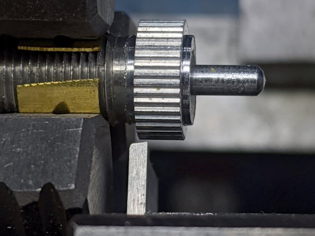
So I turned & knurled an aluminum ring, then tapped a 3×0.5 mm hole for a lock screw plucked from the Drawer o’ Random M3 Screws:
Drag Knife – lock screw – side
A view looking along the screw shows a bit more detail around the spring:
Drag Knife – lock screw – front
The general idea is to set the blade extension, then tighten the lock screw to hold it in place, without relying on the original brass lock ring, shown here while cutting a boss for the spring:
Drag Knife – turning spring recess
The lock screw’s knurled handle just barely kisses the NPCNC’s black tool holder ring, so my guesstimated measurements were a bit off. Clamping the knife holder one itsy higher in the tool holder solved the problem.
I cranked on 300 g of spring preload and, squashed like that, the spring’s rate is now 75 g/mm. Cutting at Z=-1 mm should suffice for laminated paper slide rule decks.
The original sizing doodle:
Drag Knife Holder – lock screw ring doodle
The short 18 mm section clears the inside of the LM12UU bearing, although it could be a millimeter shorter. The 19 mm section comes from the 3/4 inch aluminum rod I used, skim-cut to clean it up.
If I ever remake this thing, it needs a major re-think to get all the dimensions flying in formation again.
This came about while tinkering up a shade for a repurposed LED downlight:
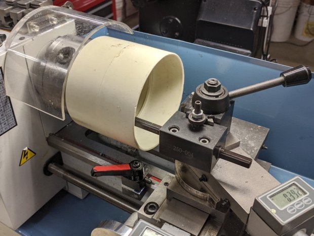
PVC fitting – boring setup
It’s a 4 inch DWV pipe coupling I bored out to fit the LED housing, which was ever so slightly larger than the pipe OD.
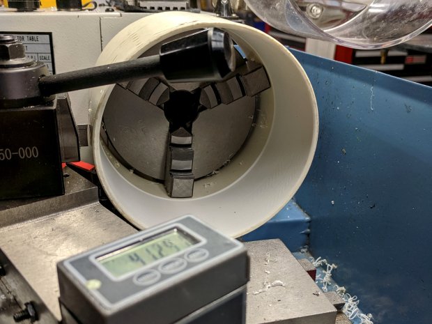
Cutting it off required as much workspace as the poor little lathe had:
PVC fitting – cutoff setup
Ignore the toolpost handle across the top. What’s important: the cutoff blade poking out of the QCTP, above the orange carriage stop lock lever, extending just far enough to cut through the coupling’s wall before the compound hits the coupling. The compound slide is all the way out against the cross-slide DRO, rotated at the only angle putting the tool where it needs to be and clearing the end of the coupling.
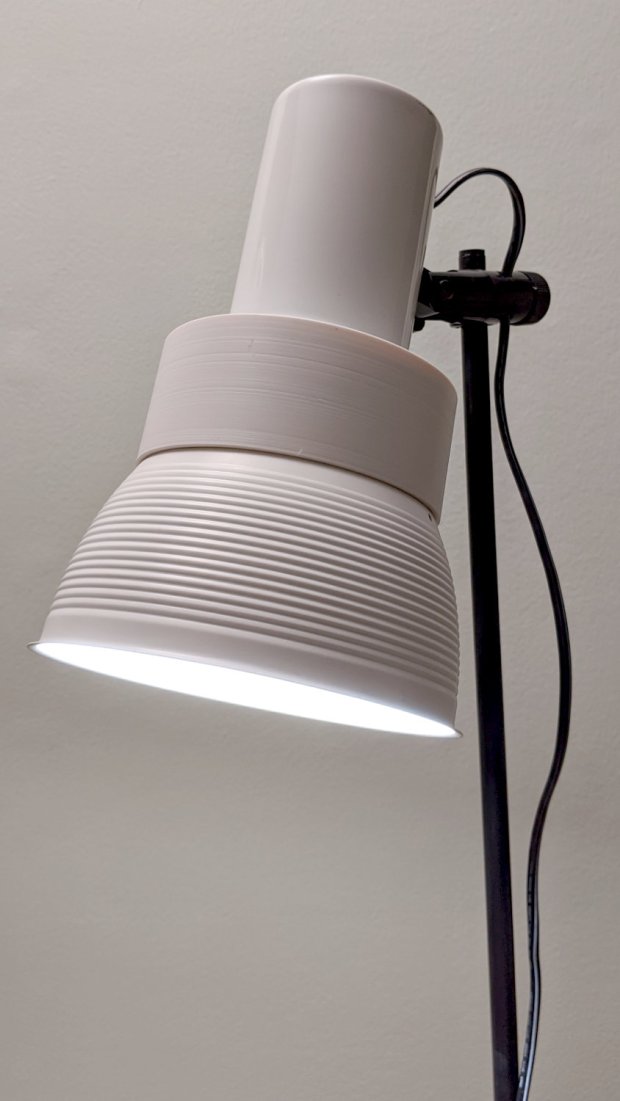
It ended reasonably well:
PVC fitting – LED floor lamp
But, in retrospect, was hideously bad practice. Next time, I’ll make a fixture to hold the fitting on a faceplate.
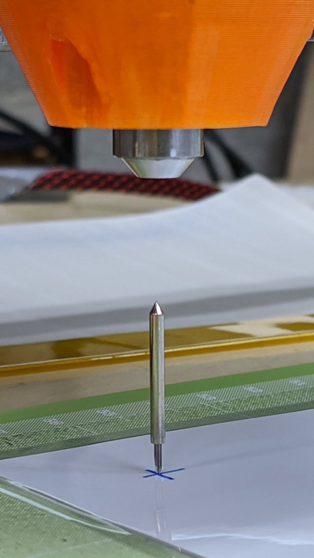
Attempting to cut laminated cardstock decks for the Homage Tektronix Circuit Computer required a bit more blade extension than my LM12UU holder made available:
Drag Knife – LM12UU ground shaft – assembled
Shortening the 12 mm shaft wasn’t going to happen, so I knocked a little bit off the blade holder to give the knurled lock ring slightly more travel:
Drag Knife Holder – shortening stop
The lathe cutoff blade is a bit to the right of the new cut, but you get the general idea: not a whole lot of clearance in there.
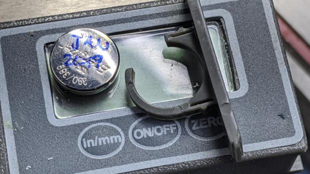
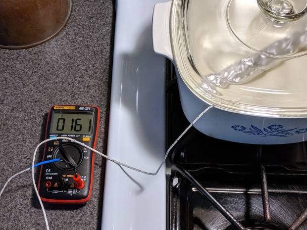
The Mini-Lathe DROs eat a 390 alkaline coin cell a year, more or less:
Mini-Lathe DRO – battery life
The other DRO’s cell was 10 mV higher, so it might have survived another few weeks. I’ll call it a year, as the OEM cells failed half a year after I got the thing and these are the second set.
The last time I did this, I wedged a thin foam sheet below the display PCB to put a bit more pressure on the (+) contact tab sticking down from the middle of the plate:
Mini-Lathe DRO – battery compartment
The (-) contact is a pad on the PCB below the battery compartment. The glaring metal reflector is part of the curved cell retainer.
I finally decommissioned my old Thing-O-Matic, as it’s been far surpassed by the current generation of dirt-cheap Prusa-style 3D printers, and must now figure out what to do with about 10 kg of 3 mm ABS filament. Yes, 3 mm filament from back in the Bad Old Days.
Also back in the day, our Larval Engineer made millifiori creations in glass (at school) and polymer clay, building up the final piece from murrine canes, which suggested a similar technique using filament strands:
Filament Millefiori – 160C pipe – slice detail
Well, maybe it’s not exactly art …
Just to see how it might work, I packed a random length of conduit with filament snippets and jammed a thermocouple into the middle:
Filament Millefiori – packed conduit
Which went into the shop’s sacrificial Dutch oven over low heat:
Some persuasion with a hammer and drift punch extracted the fused filament:
Filament Millefiori – 250C results
Obviously, the concept needs more work, but the bottom side looks promising:
Filament Millefiori – 250C results – bottom
Wrapping the bundle with silicone tape should keep the filament from sticking to the tube and provide uniform compression:
Filament Millefiori – 235C silicone wrap
I forced it into the tube and wrapped the whole affair with aluminum foil to confine the hot ABS stench:
Filament Millefiori – 235C heating
I held this one at 235 °C for a few minutes, cooled, unwrapped, and discovered the silicone wrap worked as expected:
Filament Millefiori – 235C thermocouple blob
OK, the blob on each end wasn’t expected, but at least the thermocouple came out with gentle persuasion. The compressed filament looked like it should be edible:
Filament Millefiori – 235C results
The molten filament oozed out of the wrap inside the tube, over there toward the right.
The filament snippets have a distinct curvature, brought on by years spent snuggled around a spool’s core, so I wondered if they could be straightened by application of somewhat less heat. Wikipedia lists the glass transition temperature for various ABS compositions as around 105 °C, so I packed the tube with more snippets and affixed the thermocouple with silicone tape:
Filament Millefiori – 100C setup
Wrap with foil, heat to 100 °C, let cool, and they’re definitely straighter than the unheated white strand at the bottom:
Filament Millefiori – 100C results
Having learned my lesson with a thermocouple inside the strands, the straightened strands get a looser silicone wrap with the thermocouple secured to the outside of the bundle:
Filament Millefiori – 160C setup
Heat to 160 °C:
Filament Millefiori – 160C setup
Let cool and (easily!) slide the compressed bundle out of the tube:
Filament Millefiori – 160C cooling
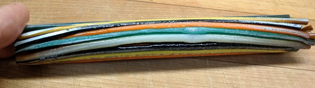
The silicone wrap definitely mushed the strands together, as shown by the larger diameter on the uncompressed end:
Filament Millefiori – 160C results
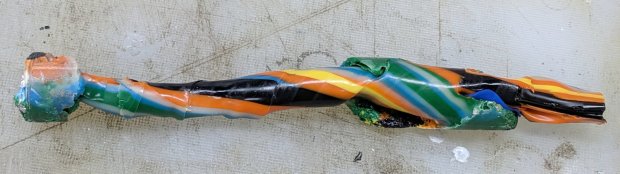
Bandsawing the bundle reveals nicely fused filaments inside, along with melty ends that stuck out of the wrap:
Filament Millefiori – 160C cut end
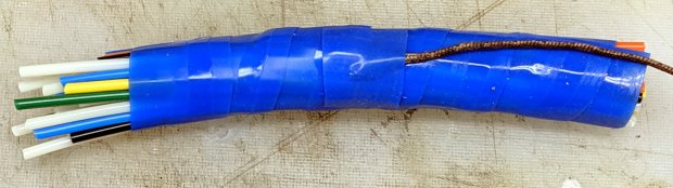
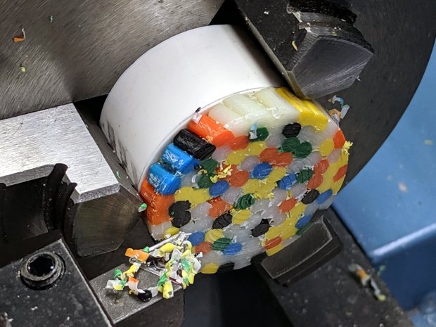
Thinking shorter lengths might pack better without straightening, I faced the ends of a thick aluminum pipe and stuffed as many snippets into it as would fit. This is the point where a real artist would arrange the filaments in a pleasing pattern, if not a picture, but I was content with a random layout:
Filament Millefiori – 160C pipe – cable in pipe
That’s what the ends looked like after heating to 160 °C: somewhat glazed, reasonably fused, but certainly not compacted. The other end pointed upward and definitely felt the heat:
Filament Millefiori – 160C pipe – cable melty end detail
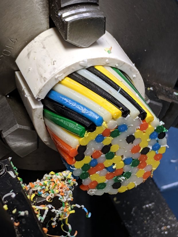
With a PCV pipe “collet” holding the cable / cane / murrina in the chuck, I faced the end:
Filament Millefiori – 160C pipe – cable facing
After taking this picture, I came to my senses and bandsawed the slice instead:
Filament Millefiori – 160C pipe – cutoff tool
Parting the slice in the lathe might have worked, but it just seemed like a really really bad idea when I looked at the setup.
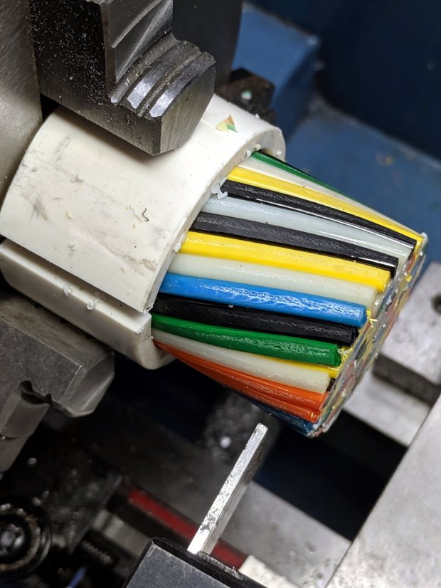
A PVC pipe spacer kept the slice lined up in the chuck jaws while facing the bandsawed end:
Filament Millefiori – 160C pipe – slice facing
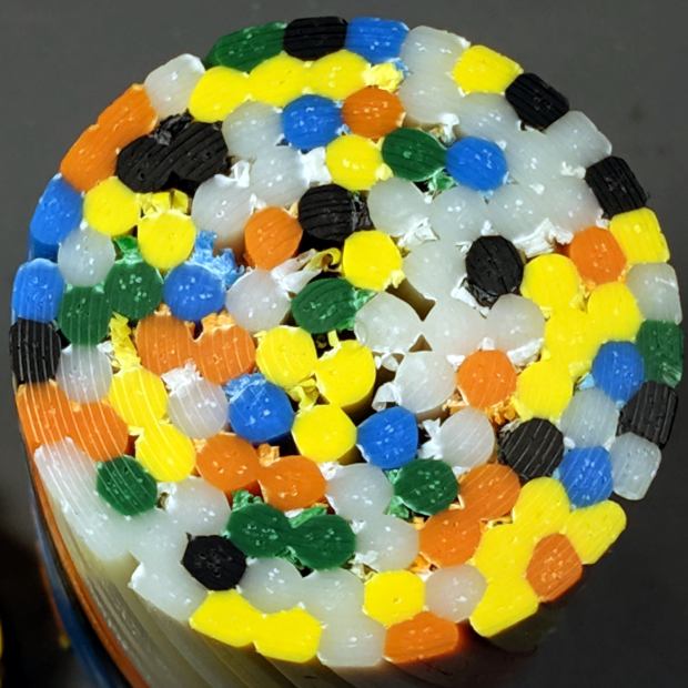
The slice and the cable:
Filament Millefiori – 160C pipe – slice and cable
Although the filament snippets fuse together without a silicone tape compression wrap, the gaps collect plenty of swarf during the cutting & facing:
Filament Millefiori – 160C pipe – cable end detail
The snippets along the outside, closest to the pipe, obviously got hotter than the ones in the middle and fused more solidly.
The pipe has a 35 mm ID for an area 136 times larger than a 3 mm filament. I packed about 100 snippets into the pipe, a 0.73 packing fraction, which looks to be in the right ballpark for the high end of the Circle Packing Problem. If they were straighter, maybe a few more would fit, but twisting the lot into a cable seemed to align them pretty well.
Perhaps filling the gaps with pourable epoxy before cutting the slices would help? A completely filled interior might require pulling a good vacuum on the whole thing.
A hexagonal pipe would produce slices one could tile into a larger sheet.
All in all, a useful exercise, but … it ain’t Art yet!
My high hopes for the UHMW bushing supporting the impeller lasted the better part of a day, because direct contact between the impeller and the motor bearing produced an absurdly loud and slowly pulsating rumble:
Bath Vent Fan – bushing installed
My hope that the UHMW would wear into a quieter configuration lasted a week …
Back in the Basement Shop, some free-air tinkering showed the impeller produced enough suction to pull itself downward along the shaft and jam itself firmly against the motor frame. My initial thought of putting a lock ring around the shaft to support the impeller turned out to be absolutely right.
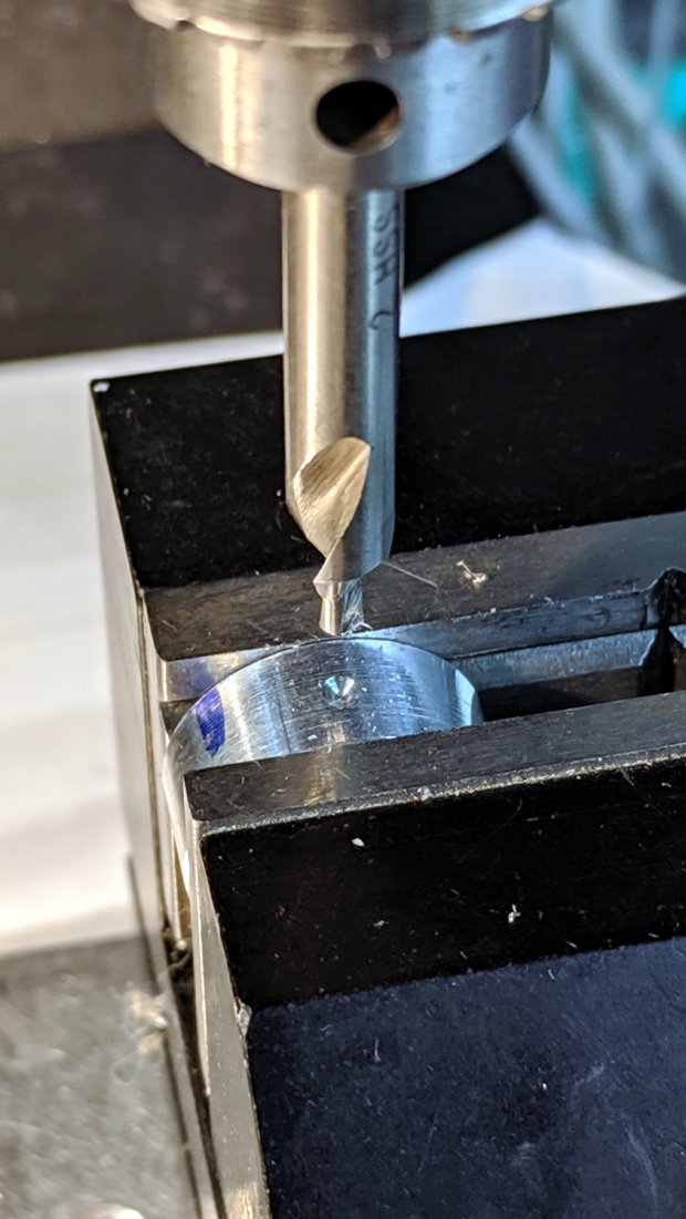
So, make a small ring:
Bath Vent Fan – small lock ring – c-drill
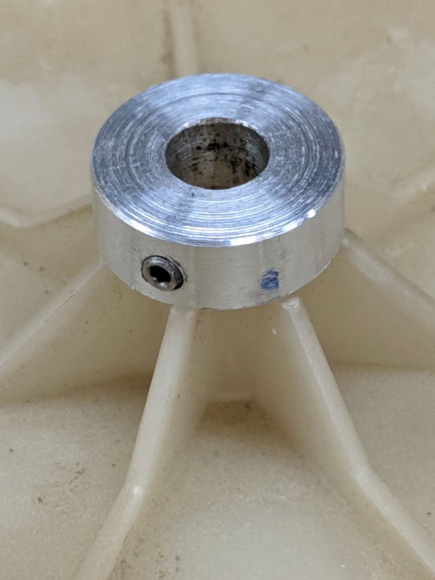
With a 4-40 setscrew in its side, perched atop the impeller for scale:
Bath Vent Fan – small lock ring – size
It just barely fits between the impeller and the motor frame:
Bath Vent Fan – small lock ring – installed
This reduced the noise, but the hole in the impeller has worn enough to let it rotate on the shaft and the rumble continued unabated. The correct way to fix this evidently requires a mount clamped to both the shaft and the impeller.
Fast-forward a day …
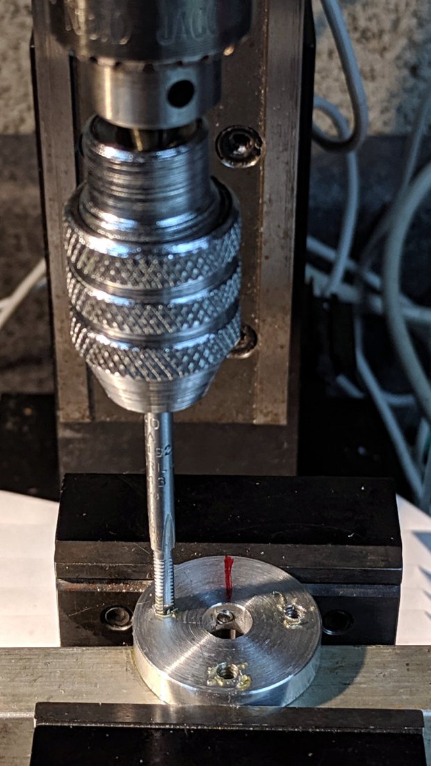
A careful look at the impeller shows seven radial ribs, probably to reduce the likelihood of harmonic vibrations. After a bit of dithering, I decided not to worry about an off-balance layout, so the screws sit on a 9 mm radius at ±102.9° = 2 × 360°/7 from a screw directly across from the setscrew in another slice from the 1 inch aluminum rod:
Bath Vent Fan – mount ring – tapping
Centered on the disk and using LinuxCNC’s polar notation, the hole positions are:
As usual, I jogged the drill downward while slobbering cutting fluid. I loves me some good manual CNC action.
Put the mount on a 1/4 inch tube, stick it into the impeller, and transfer-punch the screw holes:
Bath Vent Fan – mount ring – impeller marking
Apparently, some years ago I’d cut three screws to just about exactly the correct length:
Bath Vent Fan – mount ring – test fit – bottom
I knew I kept them around for some good reason!
The 9 mm radius just barely fits the screw heads between the ribs:
Bath Vent Fan – mount ring – test fit – top
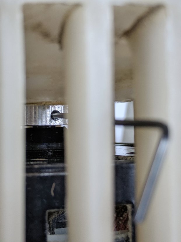
Some Dremel cutoff wheel action extended the motor shaft flat to let the setscrew rest on the bottom end:
Bath Vent Fan – mount ring – shaft flat
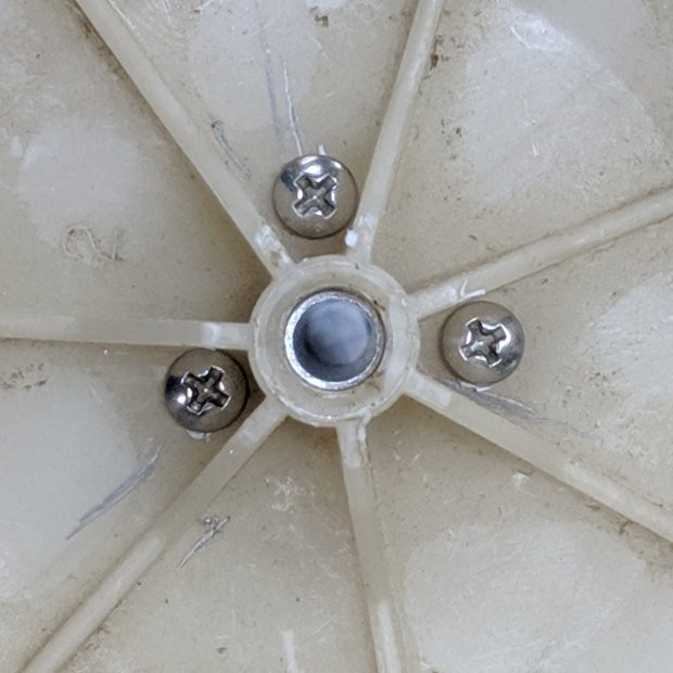
Then it all fit together:
Bath Vent Fan – mount ring – installed
The fan now emits a constant whoosh, rather than a pulsating rumble, minus all the annoying overtones. It could be quieter, but it never was, so we can declare victory and move on.
Dropping fifty bucks on a replacement fan + impeller unit would might also solve the problem, but it just seems wrong to throw all that hardware in the trash.
And, despite making two passes at the problem before coming up with a workable solution, I think that’s the only way (for me, anyhow) to get from “not working” to “good as it ever was”, given that I didn’t quite understand the whole problem or believe the solution at the start.
But it should be painfully obvious why I don’t do Repair Cafe gigs …