Ed Nisley's Blog: Shop notes, electronics, firmware, machinery, 3D printing, laser cuttery, and curiosities. Contents: 100% human thinking, 0% AI slop.
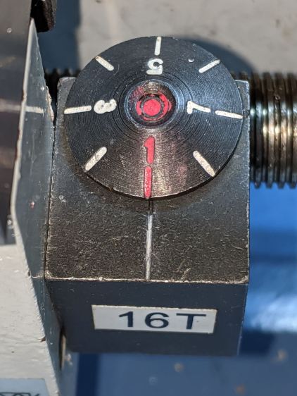
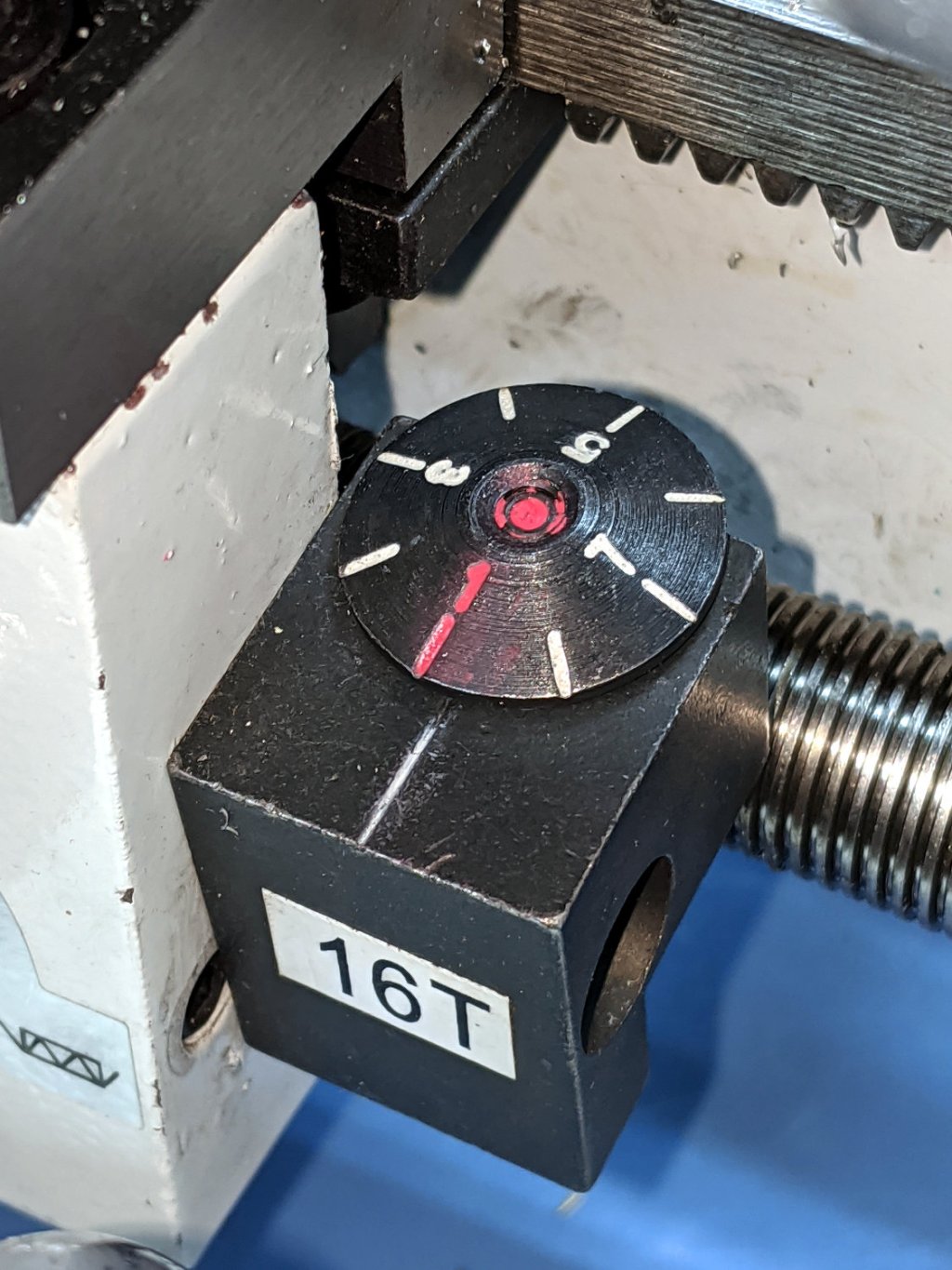
As received, the mini-lathe’s threading dial was misaligned by about 1/4 division, which is nearly halfway to the next engagement point midway between the divisions:
Mini-Lathe Threading Dial – as received – colorized
I added the red lacquer crayon while contemplating what to do, because I thought the dial was swaged onto the shaft. It turns out to be threaded, so I marked where the dial should be, grabbed the shaft in the (soft-jawed) bench vise, and twisted the dial with a Vise-Grip until it lined up:
Mini-Lathe Threading Dial – aligned
Well, it’s closer than it was, OK?
There’s about that much slop on either side of the index line coming from the loose gear engaging the leadscrew, so that’s as good as it gets.
Running my assortment of custom 3D printed change gears through the LittleMachineShop calculator and copying the results into a spreadsheet for E-Z formatting produces a useful table:
Although OpenSCAD’s MCAD library includes a gear generator, I don’t profess to understand the relations between reality and its myriad parameters, plus I vaguely recall it has a peculiar definition for Diametral Pitch (or some such). Rather than fiddle with all that, I start with an SVG outline from Inkscape’s Gears extension and go all 3D on it.
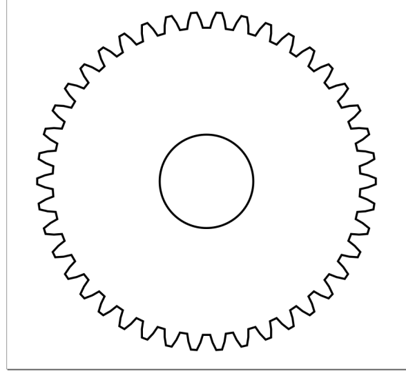
So, the “gear blank” looks like this after extruding the SVG:
Mini-lathe change gear – 42 tooth – SVG import
Producing this is a lot easier in OpenSCAD than in real life:
Mini-lathe change gear – 42 tooth – solid model
OpenSCAD centers the blank’s bounding box at XY=0, which won’t be exactly on the bore centerline for gears with an odd number of teeth. One tooth sits at 0° and two teeth bracket 180°, so the bounding box will be a little short on one side
A reference for gear nomenclature & calculations will come in handy.
For a 21 tooth module 1 gear, which should be pretty close to the worst case in terms of offset:
Pitch dia = d = 21 × 1 = 21 mm
Tip dia = da = d + 2m = 23 mm
Tip radius = da/2 = 11.5 mm
Tooth-to-tooth angle = 360/21 = 17.143°
Radius to tangent across adjacent teeth = 11.5 × cos 17.143°/2 = 11.372 mm
An actual metal 21 tooth gear measures 22.87 mm across a diameter, dead on what those numbers predict: 11.5 + 11.372 = 22.872 mm.
So the bounding box will be 11.5 mm toward the tooth at 0° and 11.372 mm toward the gap at 180°. The offset will be half that, with the tooth at 0° sitting 0.063 mm too close to the origin. Gears with more teeth will have smaller errors.
Given that we’re dealing with a gear “machined” from plastic goo, that’s definitely close enough:
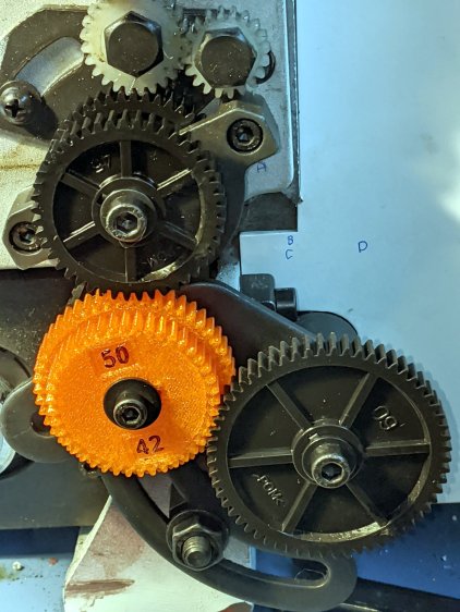
Mini-Lathe change gears – 1 mm – 45-50-45-60
That’s an earlier version with the debossed legend.
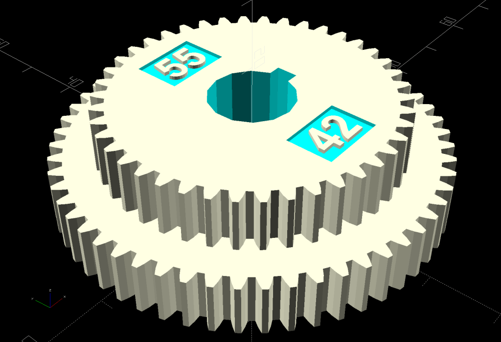
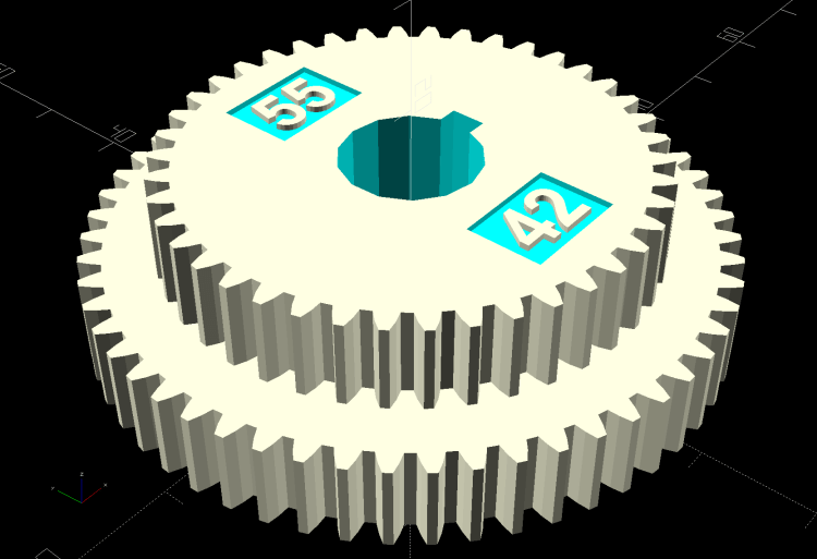
The code can also generate stacked gears for the BC shaft in the middle:
Mini-lathe change gear – 42-55 tooth stacked – solid model
In principle, the key locking the gears together isn’t needed and the bore could fit the inner shaft, rather than the keyed bushing, but then you’d (well, I’d) be at risk of losing the bushing + key in one easy operation.
This file contains hidden or bidirectional Unicode text that may be interpreted or compiled differently than what appears below. To review, open the file in an editor that reveals hidden Unicode characters.
Learn more about bidirectional Unicode characters
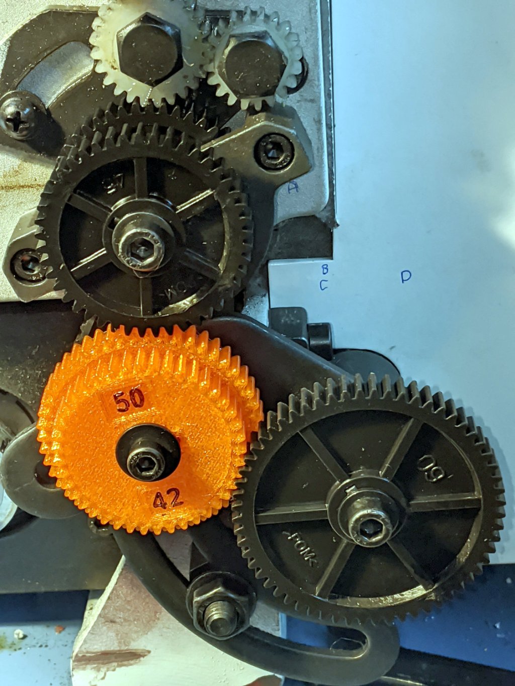
Going from a 21 tooth gear to a 42 tooth gear means you must reduce the remaining train ratio by a factor of two for a given thread pitch. Here’s a 42-50-45-60 train, with the same -125 ppm error as the 21-50-60-40 train and no screw / washer clearance issues between the A screw and the C gear:
Mini-Lathe change gears – 1 mm – 45-50-45-60
The original 60-40 CD pair has a 3:2 ratio, the 45-60 CD pair is 3:4, so that’s where the factor-of-two reduction happens.
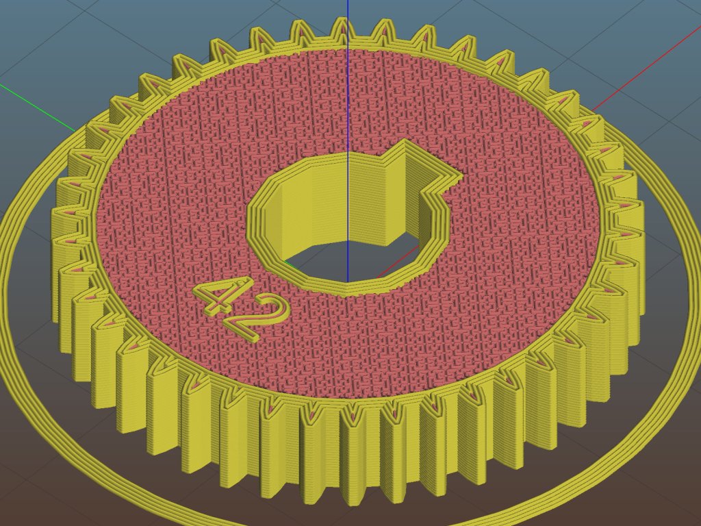
The first pass at the solid model included a debossed legend:
Mini-lathe 42 tooth change gear – Slic3r
With a printed gear in hand, I realized the legend must be embossed below the surface, so as not to rub against an adjacent gear; better modeling is in order.
The general idea is to set Inkscape’s (known-good) gear generator to the correct gear parameters (module 1 → 3.14 mm circular pitch, 20° pressure angle):
Inkscape Gear Generator dialog
Save the outline as an SVG:
Inkscape Gear Generator result
If you do like I did and neatly position the gear at the bottom-left origin, all SVG viewers will show only the Quadrant I arc, probably because Inkscape sets the SVG file to display it that way. I’ve made that mistake before and maybe, someday, I’ll remember.
Load the SVG into OpenSCAD, which will find the entire gear, no matter where it falls in the coordinate space, and spike it at the origin:
The linear_extrude( … center=false … ) keeps the bottom of the blank at Z=0. The import( … center=true … ) puts the 2D shape at the XY origin. Because OpenSCAD centers the bounding box, gears with an odd number of teeth will be ever so slightly off-center, which would matter a whole lot more in a fancier machine tool than a mini-lathe.
All of which produces a tidy 3D gear blank:
Mini-lathe change gear – 42 tooth – SVG import
OpenSCAD ignores SVG holes, which isn’t a problem for me, because I’d rather punch the bore, keyway, and so forth programatically.
While not strictly necessary for metric threading on a USA-ian mini-lathe, a 32 tooth gear can produce reasonable approximations, so I printed a pair from a Thingiverse collection:
Mini-lathe 32 tooth change gear – Slic3r
The model was designed for a slightly different mini-lathe, as it includes a short boss and thinner plate, but it did fit on the shaft:
Mini-Lathe change gears – 1 mm – bad 32 60 65 55
The gear mesh seemed odd, though, and comparing it with a standard 30 tooth gear and a different printed 32 tooth gear (about which, more later) showed it was definitely not compatible:
Mini-lathe change gears – 32 30 odd 32
Yes, the 32 tooth Thingiverse gear on the right is slightly smaller than the stock 30 tooth gear in the middle.
The larger 32 tooth gear (on the left, above) meshes better:
The real reason you need a 32 tooth gear is for exact 25, 50, and 100 TPI threads with a 1/16 inch leadscrew. I don’t foresee much need for those around here, but you can never have too many change gears …
Mini-lathes sold everywhere except the USA have hard-metric leadscrews with a 1.5 mm pitch, so they can cut metric threads without any trouble at all. USA-ian mini-lathes have hard inch leadscrews with a 1/16 inch pitch and require gymnastics to cut decent metric threads.
For inch threads:
Mini-lathe – inch thread equation
For metric threads, it’s upside-down and converted:
Mini-lathe – metric thread equation
Including a 21 tooth change gear at A or C in the train will get closer to metric threads, but the stud holding the B-C gears on my lathe imposes a minimum B gear size. Here’s a 1 mm thread with a 21-30-45-50 train:
Mini-Lathe change gears – 1 mm – 21 vs 30 tooth – AB
Oops.
You can interchange the AB and CD gear pairs, but the CD pair also has a minimum spacing:
Mini-Lathe change gears – 1 mm – 21 vs 30 tooth – CD
If it worked, the 1 mm thread would be off by -125 ppm, which is surely close enough.
Without the 21 tooth gear, the LittleMachineShop gear calculator produces a 45-55-50-65 train that fits much better, albeit with +875 ppm thread error:
Mini-Lathe change gears – 1 mm – 45 55 50 65
Dropping the 21 tooth gear into the LMS calculator produces a (barely) workable 21-50-60-40 train with -125 ppm error:
Mini-Lathe change gears – 1 mm – 21 50 60 40
The very very snug fit of the screw (omitted here) on the 21 tooth gear nearly hits the 60 tooth gear. Your mileage may vary, of course.
Varioussourcessuggest the gears are module 1, 20° pressure angle, 12 mm bore, and 8 mm thick (mine measure a scant 7.75 mm), with a 3 × 1.4 mm keyway (the key itself is 3 mm square, but it’s half-buried in the shaft).