Ed Nisley's Blog: Shop notes, electronics, firmware, machinery, 3D printing, laser cuttery, and curiosities. Contents: 100% human thinking, 0% AI slop.
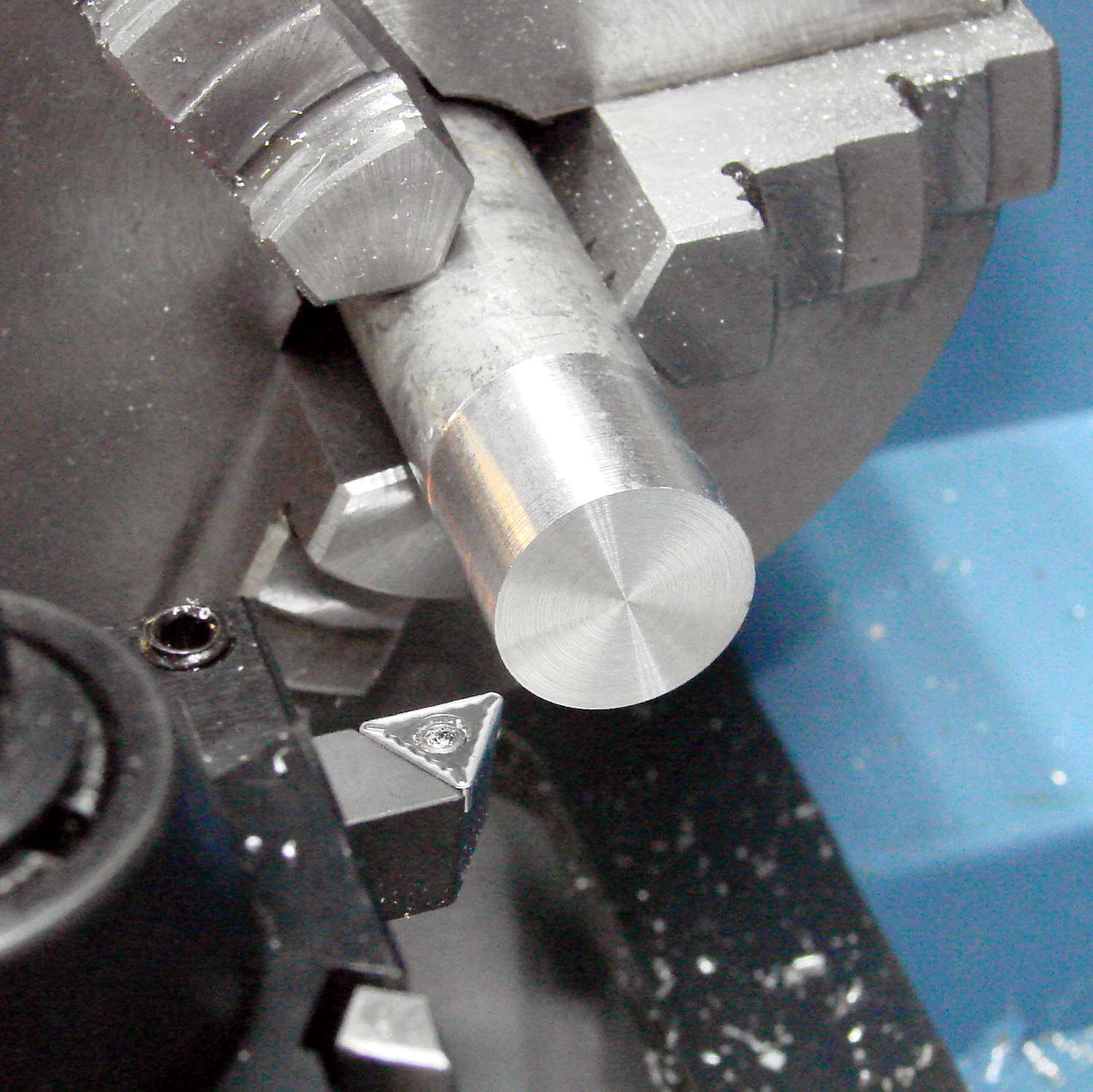
The QC post and tool holders have very nice machining and surface finish; they evidently come from an entirely different production line than the lathe components. I can definitely get used to using carbide inserts, although I ordered some HSS inserts for interrupted cuts.
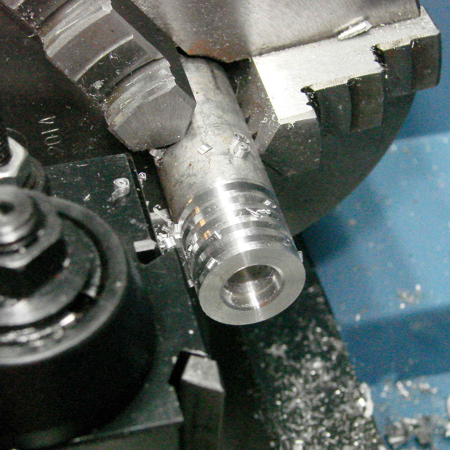
The HSS cutoff tool does what you’d expect:
LMS Mini-lathe – first cut – drilled and slotted
The holes in the end came from short (“screw machine”) drill bits I got for the Sherline’s painfully limited Z axis travel. Even so, chucking one in the 1/2 inch capacity LMS drill chuck shows why a 16 inch bed isn’t excessive:
LMS Mini-lathe – drill chuck vs bed length
The 6 inch = 150 mm scale on the bed (to the right of the tailstock) extends to the limit of tailstock travel, so you could have another half foot of stock sticking out of the 3 jaw chuck. A collet in the spindle would give you another two inches, but it’s snug in there.
On the other paw, this is a little lathe intended to make little things. It’ll do fine…
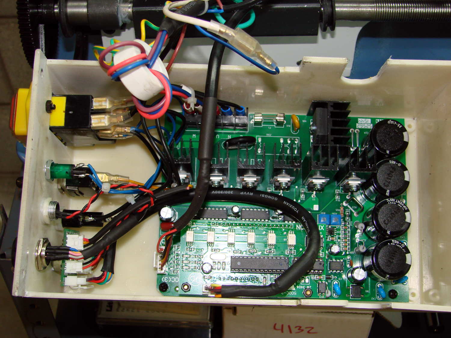
It’s easier to remove the leadscrew while dismantling the carriage and apron, which requires removing the cover from the control box containing all the switches & knobs. Come to find out the “cover” actually holds all the gadgetry onto the headstock:
LMS mini-lathe – control box interior
I want to replace the Power indicator with something visible in normal shop light; judging from the connectors and overall brightness, it’s a neon bulb inside a green housing.
Anyhow, the four screws holding cover to the headstock weren’t identical:
LMS Mini-lathe – cover screws
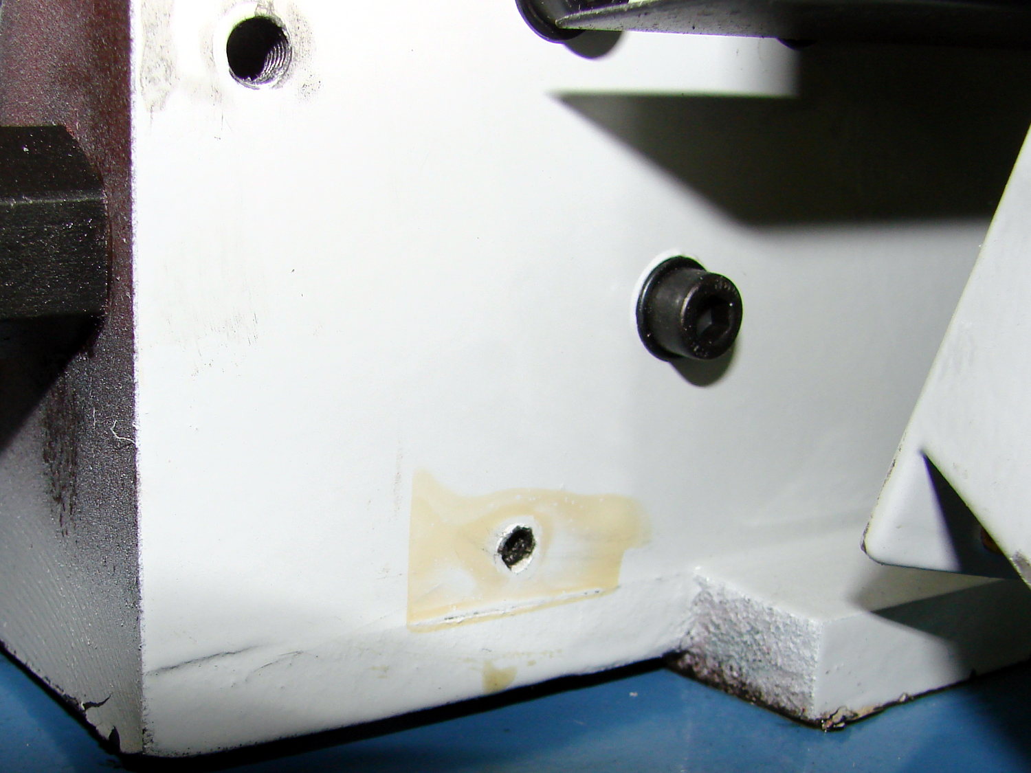
I thought the oddball screw was deliberate, perhaps fastening that corner to a plastic frame of some sort, but it turned out to be a quick fix for a boogered tap job:
LMS Mini-lathe – mistapped cover hole
A bag of 4 mm knurled brass inserts will arrive in a while, after which I’ll drill out all four holes and epoxy inserts in their place. Might have to use stainless hardware, just for nice…
The mini-lathe arrives covered in oil and the chuck is no exception. Wrap it in a paper towel, spin it up, let it sling out (nearly all) of the excess oil:
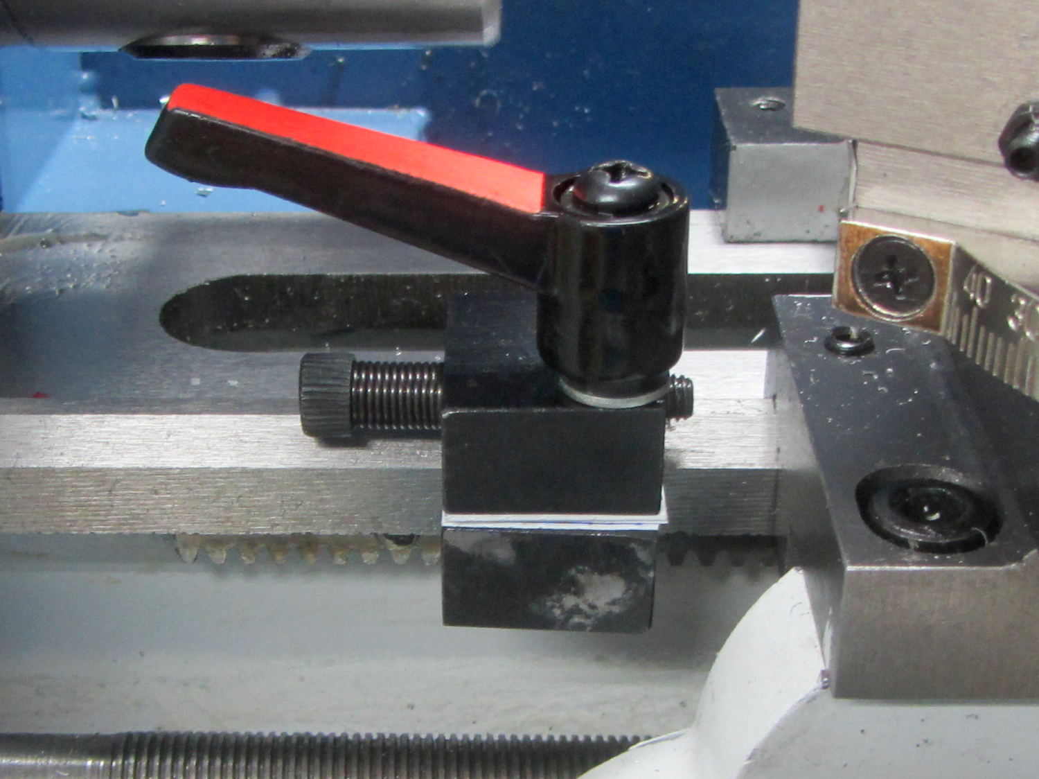
I got an LMS adjustable carriage stop along with the mini-lathe to simplify cutting things to length. A few tweaks make it much less annoying to use:
LMS Mini-lathe – carriage stop – crude shim
The fluorescent red tape makes the handle stand out vividly against the general clutter. It lives in the shadow of the chuck, where an extended jaw could end its life, so some protective coloration seemed in order.
The screw threaded into the lower part holds it together, but, as with the carriage retaining plates, only the outer edge clamped onto the lower part of the bed. Three layers of credit card plastic fill the gap and allow just enough compression to go from “freely sliding” to “firmly clamped” in half a turn of the lever.
The washer lets the lever turn easily on the upper block.
Remove the screw and spring from the lever to lift and properly re-index it on the internal nut.
The spring on the adjusting screw seems too long and exceedingly stiff for the task at hand. The Big Box o’ Little Springs didn’t offer a suitable replacement, so adapting / making one goes on the to-do list.
It really needs a sliding pin just to the left of the lever screw to hold the lower block in alignment, but that’s definitely in the nature of fine tuning.
Eks gave the traverse crank a few twirls, told me the gear was engaging the rack entirely too tightly, and recommended shimming the apron:
LMS mini-lathe – apron shim
Of course, he was right.
Took two 18 mil shims to make it feel right, for whatever that’s worth.
That isn’t the prettiest solution, but it’ll suffice until the ways wear a bit more, things settle in, and I can cut a proper shim to surround the bolt holes across the entire bearing surface.
You can just make out the transparent plastic sheet that serves as a chip shield around the traverse gear shaft; kudos to LMS for that upgrade.
A chip shield tube / roof over the leadscrew is in order, too.
While mulling over the DRO situation, I clamped the compound rest to the cross slide, backed the knob to the limit of the backlash, and poked feeler gauges into the opening:
LMS mini-lathe – measuring compound backlash
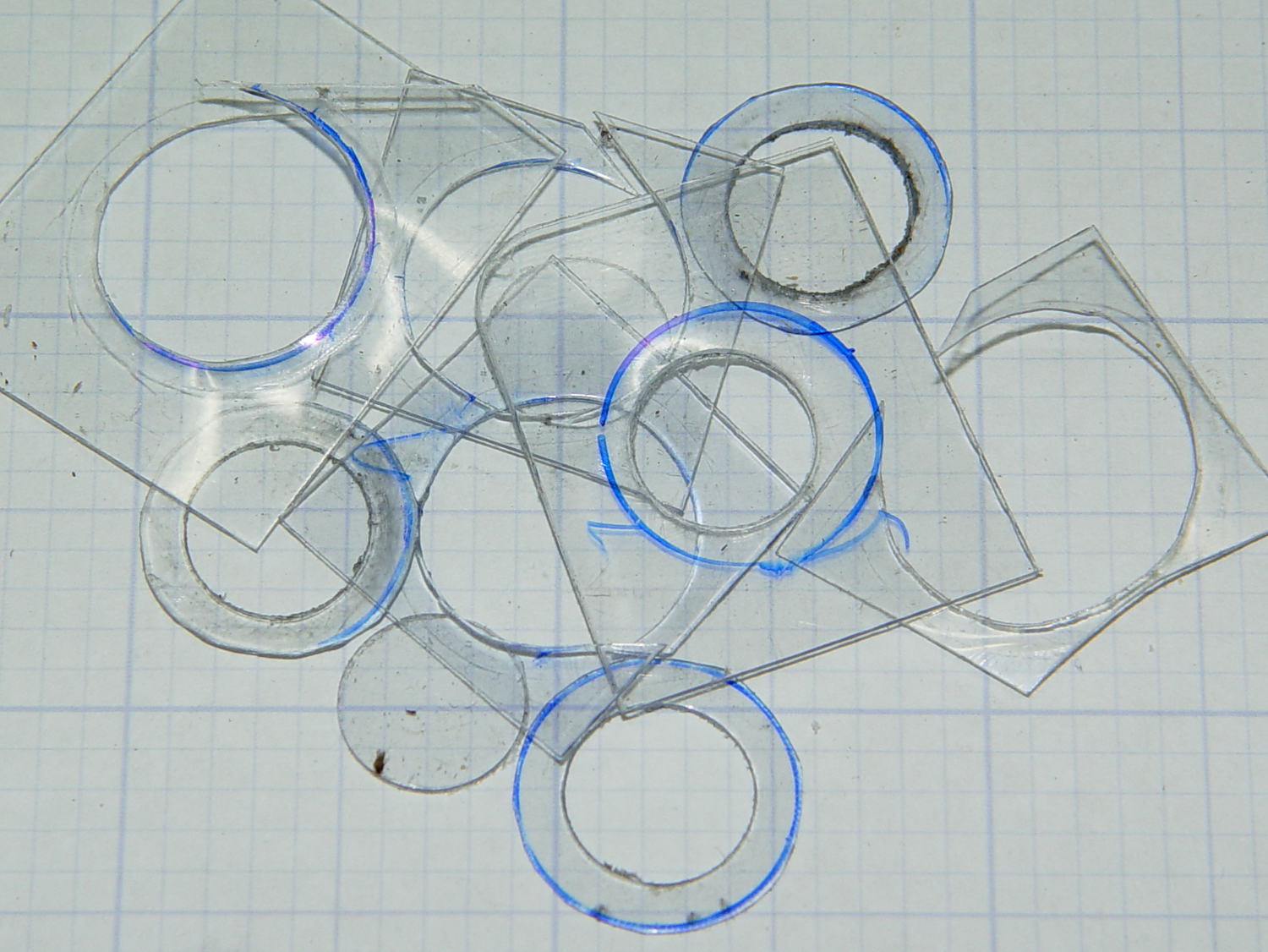
The backlash turned out to be around 20 mil = 0.020 inch = 0.5 mm, which seemed excessive to me, so I fiddled around with the contents of the Big Box o’ Polypropylene Sheets (harvested from various clamshell retail packages), deployed the hollow punches, performed some deft scissors work, and made some shims:
LMS mini-lathe – compound knob shims
Eventually, one of ’em offered a Good Enough combination of reduced backlash and E-Z turning to suffice for now. The proper solution involves facing off / rebuilding the fat metal washer on the right to put the bore at right angles to the bearing surfaces, but that’s another project.
The final backlash ended up around 4 mils, with a bit of drag due to the slightly irregular metal washer on the left preventing anything tighter. The cross slide knob also has a bit of backlash, but the thinnest sheets are a bit too thick.
Polypropylene isn’t the right plastic for a bearing, but it’s cheap, readily available, easily worked, and served as a bring-along project at Squidwrench…
The Little Machine Shop 5200 lathe package includes DROs on the cross slide and compound cranks. The readouts report the position of the crank, not the slide position, which isn’t a major problem on a lathe.
Unfortunately, the compound collides with the DRO on the cross slide:
LMS Mini-lathe – compound vs DRO
That is a major problem on a lathe.
When you can’t turn the cross slide more than 45° from parallel with the bed, you cannot set the compound to the (typical) 29° degrees required for (traditional) thread cutting. That’s measured perpendicular to the bed, so it would be 61° on the compound rest scale, if the scale went that high:
LMS Mini-lathe – compound way
This mess doesn’t have a trivial fix, because the DRO body under the (non-removable) display doesn’t quite clear the compound screw:
LMS Mini-lathe – compound vs DRO – bottom
As nearly as I can tell, removing the entire DRO is the only way to slew the compound beyond 45°, but the DRO replaced the usual manual scale around the cross slide knob, so there’s no analog backup.
The DRO mounts to the cross slide with three screws, so you can’t rotate it 90° to the side to get better clearance:
LMS mini-lathe – DRO mounting screws
The other four screws presumably mount the DRO encoder housing to the outer shell.
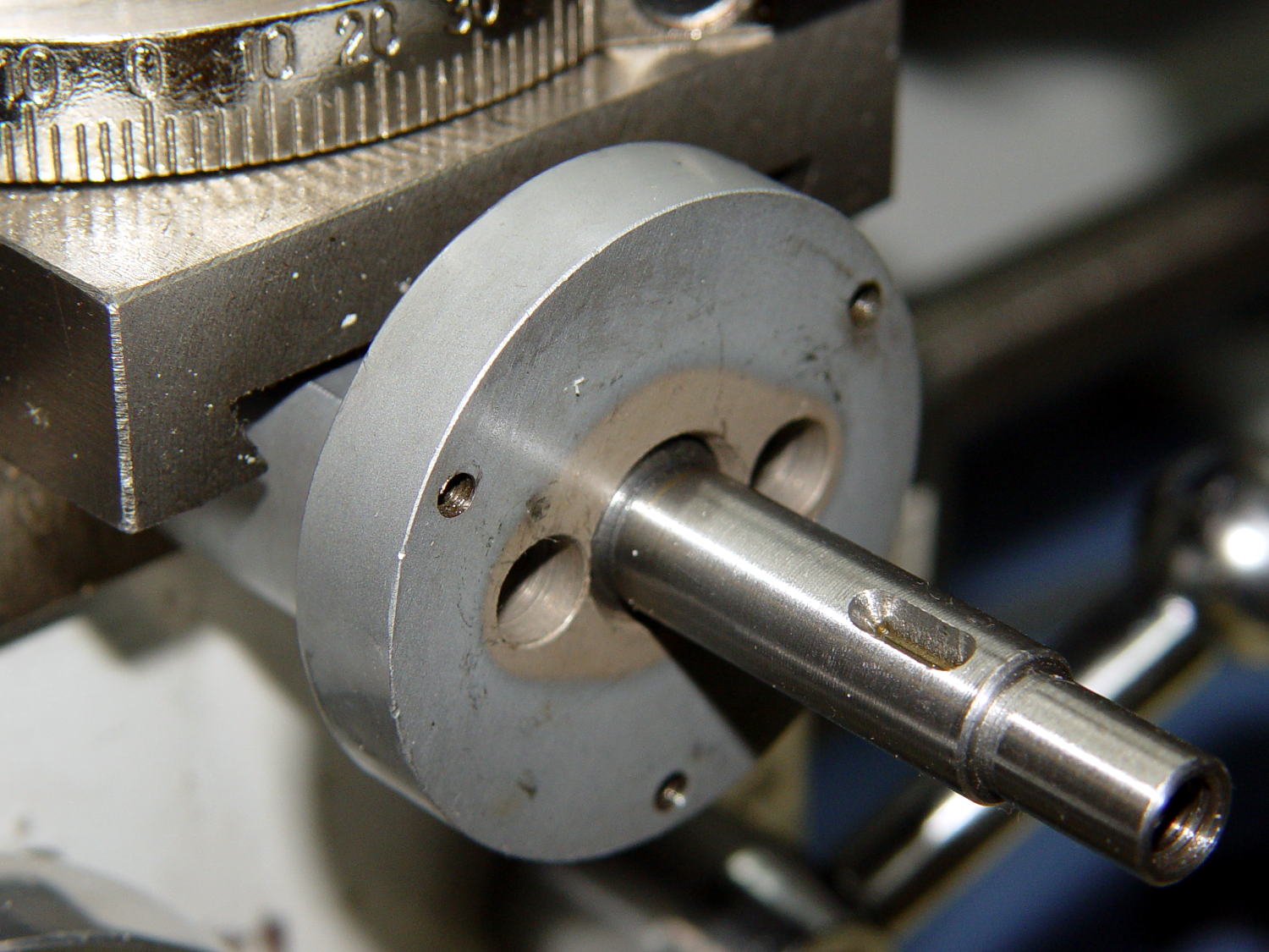
The setscrew sticking up from the sleeve anchors it to the cross slide shaft. The slit milled into the shaft captures the end of the setscrew:
LMS mini-lathe – cross slide leadscrew shaft
The knob slides over the shaft, with a screw in the end holding it in place by friction against a split lockwasher; you can apply enough torque to turn the knob under the lockwasher in either direction.
Removing the DRO doesn’t produce more cross slide travel, because the DRO body sits flush with the back side of that large disk.
I think the cross slide knob collides with the compound DRO, but I put it all back together without any further exploration.
Actual 6 inch DROs based on linear encoders seem to run $40-ish and other folks have fitted them to their mini-lathes. Verily, I don’t do much threadcutting, so I’ll just put this mess on the far back burner.
That DRO ticks me off every time I look at it, though…