Ed Nisley's Blog: Shop notes, electronics, firmware, machinery, 3D printing, laser cuttery, and curiosities. Contents: 100% human thinking, 0% AI slop.
Natural PLA provides a nice, crystalline appearance:
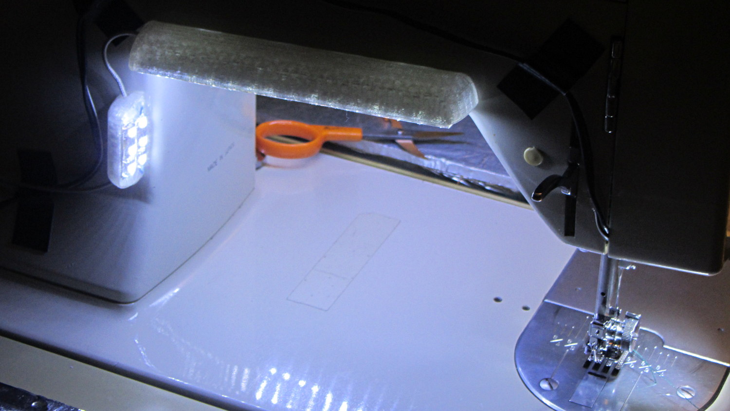
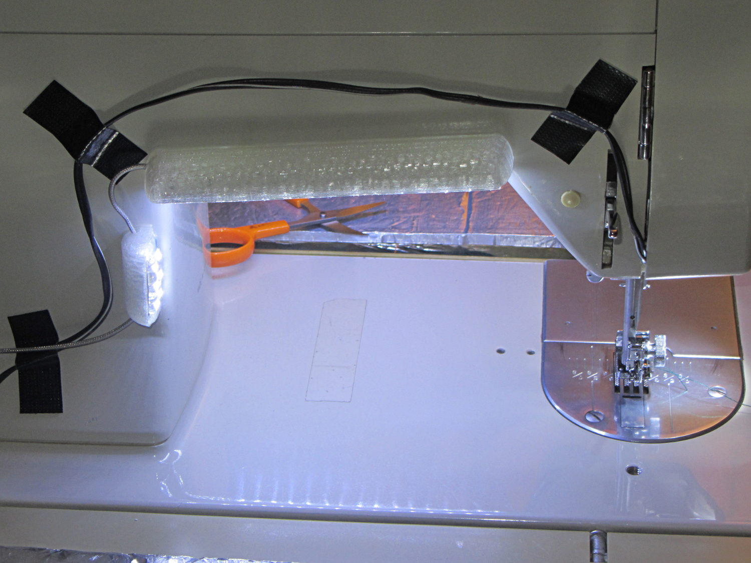
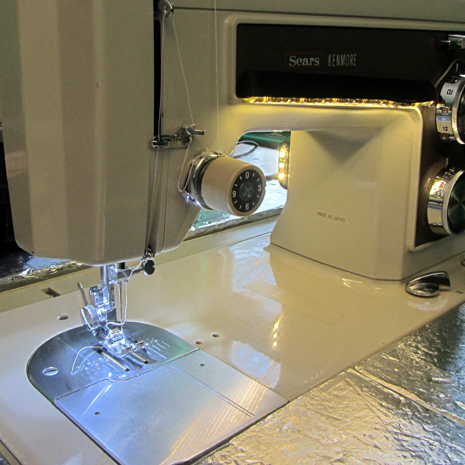
Kenmore 158 Sewing Machine – Cool white LEDs – rear no flash
Cool white LEDs have somewhat higher lumen/watt efficiency, but the real gain came from doubling the number of LEDs:
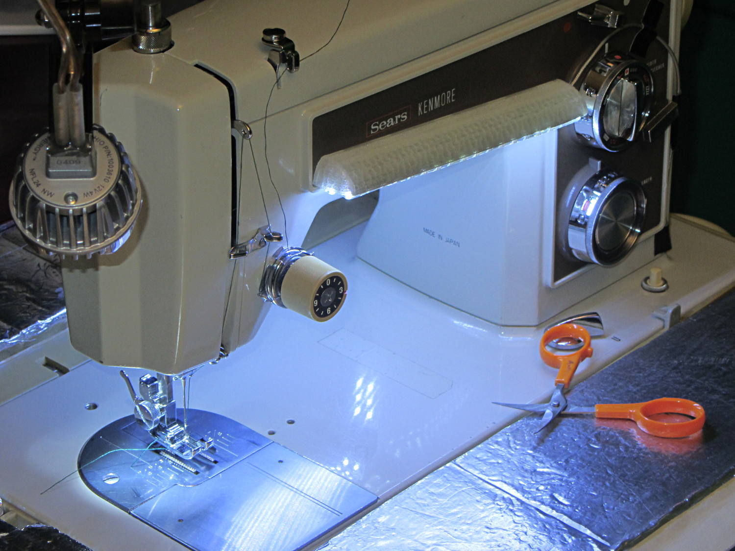
Kenmore 158 Sewing Machine – Cool white LEDs – front flash
I overvolted the warm white LEDs to 14 V to get closer to 20 mA/segment, but the cool white ones run pretty close to 20 mA at 12 V, so I didn’t bother.
Commercial versions of this hack secure the wiring with little white clips and foam tape, so I should conjure up something like that. Mary specifically did not want the lights affixed under the arm, though, so those things weren’t even in the running.
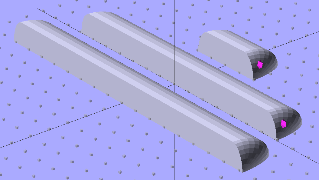
The OpenSCAD source code widens the mount and moves the wiring conduit a little bit, to simplify the connections to both strips, but is otherwise identical to the earlier version:
// LED Strip Lighting Brackets for Kenmore Model 158 Sewing Machine
// Ed Nisley - KE4ZNU - March 2014

Layout = "Build";			// Build Show Channels Strip

//- Extrusion parameters must match reality!
//  Print with 2 shells and 3 solid layers

ThreadThick = 0.20;
ThreadWidth = 0.40;

HoleWindage = 0.2;			// extra clearance

Protrusion = 0.1;			// make holes end cleanly

AlignPinOD = 1.70;			// assembly alignment pins: filament dia

inch = 25.4;

function IntegerMultiple(Size,Unit) = Unit * ceil(Size / Unit);

//----------------------
// Dimensions

Segment = [25.0,10.0,3.0];		//  size of each LED segment
SEGLENGTH = 0;
SEGWIDTH = 1;
SEGHEIGHT = 2;

WireChannel = 3.0;				// wire routing channel

StripHeight = 12.0;				// sticky tape width
StripSides = 8*4;

DefaultLayout = [1,2,"Wire","NoWire"];
NUMSEGS = 0;
NUMSTRIPS = 1;
WIRELEFT = 2;
WIRERIGHT = 3;

EndCapSides = StripSides;

CapSpace = 2.0;						// build spacing for endcaps
BuildSpace = 3.0;					// spacing between objects on platform

//----------------------
// Useful routines

module PolyCyl(Dia,Height,ForceSides=0) {			// based on nophead's polyholes

  Sides = (ForceSides != 0) ? ForceSides : (ceil(Dia) + 2);

  FixDia = Dia / cos(180/Sides);

  cylinder(r=(FixDia + HoleWindage)/2,
           h=Height,
           $fn=Sides);
}

module ShowPegGrid(Space = 10.0,Size = 1.0) {

  RangeX = floor(100 / Space);
  RangeY = floor(125 / Space);

	for (x=[-RangeX:RangeX])
	  for (y=[-RangeY:RangeY])
		translate([x*Space,y*Space,Size/2])
		  %cube(Size,center=true);

}

//-- The negative space used to thread wires into the endcap

module MakeWireChannel(Layout = DefaultLayout,Which = "Left") {

	EndCap = [(2*WireChannel + 1.0),Layout[NUMSTRIPS]*Segment[SEGWIDTH],StripHeight];	// radii of end cap spheroid

	HalfSpace = EndCap[0] * ((Which == "Left") ? 1 : -1);

	render(convexity=2)
	translate([0,Segment[SEGWIDTH]/2,0])
		intersection() {
			union() {
				cube([2*WireChannel,WireChannel,EndCap[2]],center=true);
				translate([-2*EndCap[0],0,EndCap[2]/2])
					rotate([0,90,0]) rotate(180/6)
						PolyCyl(WireChannel,4*EndCap[0],6);
			}
			translate([HalfSpace,0,(EndCap[2] - Protrusion)]) {
				cube(2*EndCap,center=true);
			}
		}
}

//-- The whole strip, minus wiring channels

module MakeStrip(Layout = DefaultLayout) {

	EndCap = [(2*WireChannel + 1.0),Layout[NUMSTRIPS]*Segment[SEGWIDTH],StripHeight];	// radii of end cap spheroid

	BarLength = Layout[NUMSEGS] * Segment[SEGLENGTH];				// central bar length

	hull()
		difference() {
			for (x = [-1,1])						// endcaps as spheroids
				translate([x*BarLength/2,0,0])
					resize(2*EndCap) rotate([0,90,0]) sphere(1.0,$fn=EndCapSides);
			translate([0,0,-EndCap[2]])
				cube([2*BarLength,3*EndCap[1],2*EndCap[2]],center=true);
			translate([0,-EndCap[1],0])
				cube([2*BarLength,2*EndCap[1],3*EndCap[2]],center=true);
		}

}

//-- Cut wiring channels out of strip

module MakeMount(Layout = DefaultLayout) {

	BarLength = Layout[NUMSEGS] * Segment[SEGLENGTH];

	difference() {
		MakeStrip(Layout);
		if (Layout[WIRELEFT] == "Wire")
			translate([BarLength/2,0,0])
				MakeWireChannel(Layout,"Left");
		if (Layout[WIRERIGHT] == "Wire")
			translate([-BarLength/2,0,0])
				MakeWireChannel(Layout,"Right");
	}
}

//- Build it

ShowPegGrid();

if (Layout == "Channels") {
	translate([ (2*WireChannel + 1.0),0,0]) MakeWireChannel(DefaultLayout,"Left");
	translate([-(2*WireChannel + 1.0),0,0]) MakeWireChannel(DefaultLayout,"Right");
}

if (Layout == "Strip") {
	MakeStrip(DefaultLayout);
}

if (Layout == "Show") {
	MakeMount(DefaultLayout);
}

if (Layout == "Build") {

	translate([0,(3*Segment[SEGWIDTH]),0]) MakeMount([1,2,"Wire","Wire"]);		// rear left side, vertical
	translate([0,0,0]) MakeMount([5,2,"Wire","NoWire"]);				// rear top, across arm
	translate([0,-(3*Segment[SEGWIDTH]),0]) MakeMount([6,2,"NoWire","Wire"]);	// front top, across arm
}
The game plan: drop a small object through a laser beam that shines on a photodiode, thus causing an electrical signal that triggers various flashes and cameras and so forth and so on. This fixture holds the laser and photodiode in the proper orientation, with enough stability that you (well, I) can worry about other things:
Laser-photodiode fixture – on blade
It’s mounted on the blade of a dirt-cheap 2 foot machinist’s square clamped to the bench which will probably get a few holes drilled in its baseplate for more permanent mounting.
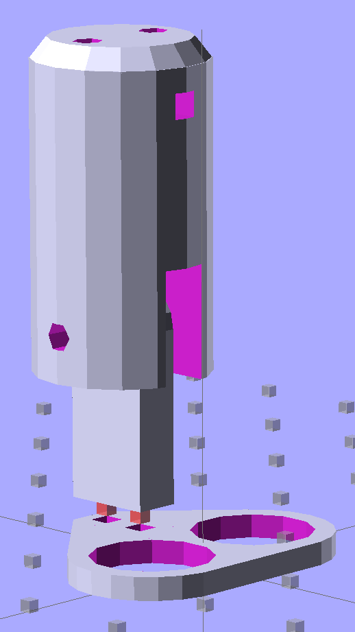
The solid model looks about like you’d expect:
Laser-photodiode fixture – solid model
There’s a small hole in the back for an 8-32 setscrew that locks it to the blade; the fit turned out snug enough to render the screw superfluous. I added those two square blocks with the holes after I taped the wires to the one in the picture.
The two semicircular (well, half-octagonal) trenches have slightly different diameters to suit the heatshrink tubing around the photodiode (a.k.a., IR LED) and brass laser housing. A dab of fabric adhesive holds the tubes in place, in addition to the Gorilla Tape on the ends.
The laser came focused at infinity, of course. Unscrewing the lens almost all the way put the focus about 3/4 of the way across the ring; call it 40 mm. The beam is rectangular, about 1×2 mm, at the center of the ring, and I rotated the body to make the short axis vertical; that’s good enough for my purposes.
The cable came from a pair of cheap earbuds with separate Left/Right pairs all the way from the plug.
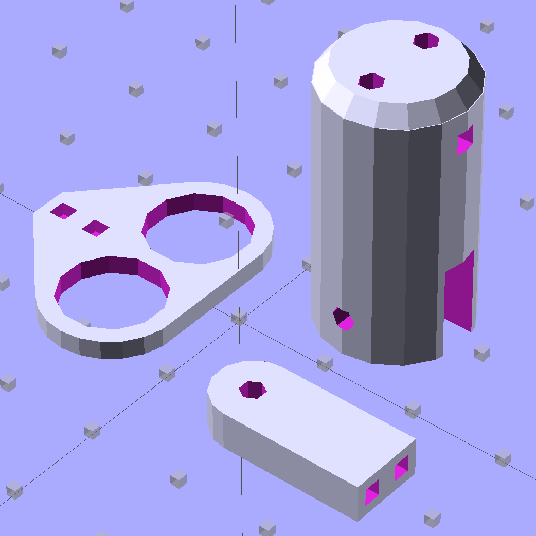
The model builds in one piece, of course, and pops off the platform ready to use:
Laser-photodiode fixture – on platform
If you were doing this for an analytic project, you’d want a marker for the beam centerline on the vertical scale, but that’s in the nature of fine tuning. As it stands, the beam sits 8 mm above the base and flush with the top surface of the ring; if that were 10 mm, it’d be easier to remember.
The OpenSCAD source code has a few tweaks and improvements:
// Laser and LED-photodiode break-beam sensor
// Ed Nisley - KE4ZNU - March 2014

Layout = "Show";			// Build Show Ring Mount Guide

//- Extrusion parameters must match reality!
//  Print with 2 shells and 3 solid layers

ThreadThick = 0.20;
ThreadWidth = 0.40;

HoleWindage = 0.2;			// extra clearance

Protrusion = 0.1;			// make holes end cleanly

AlignPinOD = 1.70;			// assembly alignment pins: filament dia

inch = 25.4;

function IntegerMultiple(Size,Unit) = Unit * ceil(Size / Unit);

//----------------------
// Dimensions

LaserOD = 6.0;				// brass focus tube
LaserLength = 20.0;			//  ... wire clearance

SensorOD = 6.5;				// including light shield
SensorLength = 20.0;		//  ... wire clearance

RingSize = [50.0,70.0,8.0,8*4];	// support ring dimensions
RING_ID = 0;
RING_OD = 1;
RING_THICK = 2;
RING_SIDES = 3;

StrutWidth = 2.5;					// strut supporting this thing
StrutLength = 26.5;

StrutBlock = [10.0,35.0,20.0];		// block around the clearance slot
BLOCK_WIDTH = 0;
BLOCK_LENGTH = 1;
BLOCK_HEIGHT = 2;

StrutScrewTap = 2.7;				// 6-32 SHCS

GuideID = 4.0;						// guide for cables
GuideOD = 3*GuideID;

BuildSpace = 3.0;					// spacing between objects on platform

//----------------------
// Useful routines

module PolyCyl(Dia,Height,ForceSides=0) {			// based on nophead's polyholes

  Sides = (ForceSides != 0) ? ForceSides : (ceil(Dia) + 2);

  FixDia = Dia / cos(180/Sides);

  cylinder(r=(FixDia + HoleWindage)/2,
           h=Height,
           $fn=Sides);
}

module ShowPegGrid(Space = 10.0,Size = 1.0) {

  RangeX = floor(100 / Space);
  RangeY = floor(125 / Space);

	for (x=[-RangeX:RangeX])
	  for (y=[-RangeY:RangeY])
		translate([x*Space,y*Space,Size/2])
		  %cube(Size,center=true);

}

module Ring() {

	difference() {
		union() {
			rotate(180/RingSize[RING_SIDES])
				cylinder(d=RingSize[RING_OD],h=RingSize[RING_THICK],
						$fn=RingSize[RING_SIDES]);
			translate([-LaserOD,(-LaserLength - RingSize[RING_ID]/2),0])
				cube([2*LaserOD,LaserLength,RingSize[RING_THICK]],center=false);
			translate([-SensorOD,(-0*SensorLength + RingSize[RING_ID]/2),0])
				cube([2*SensorOD,SensorLength,RingSize[RING_THICK]],center=false);
		}
		rotate(180/RingSize[RING_SIDES])
			translate([0,0,-Protrusion])
				cylinder(d=RingSize[RING_ID],h=(RingSize[RING_THICK] + 2*Protrusion),
						$fn=RingSize[RING_SIDES]);
		translate([0,0,RingSize[RING_THICK]])
			rotate([90,0,0]) rotate(180/8)
				PolyCyl(LaserOD,3*LaserLength,8);
		translate([0,0,RingSize[RING_THICK]])
			rotate([-90,0,0]) rotate(180/8)
				PolyCyl(SensorOD,3*SensorLength,8);
	}
}

module Mount() {
	translate([0,0,StrutBlock[2]/2])
		difference() {
			cube(StrutBlock,center=true);
			cube([StrutWidth,StrutLength,2*StrutBlock[2]],center=true);
			translate([0,-StrutLength/3,0])
				rotate([90,0,0])
					PolyCyl(StrutScrewTap,StrutLength/2,6);
		}
}

module Guide() {

	difference() {
		translate([0,0,RingSize[RING_THICK]/2])
			cube([GuideOD,GuideOD,RingSize[RING_THICK]],center=true);
		translate([0,0,-Protrusion]) rotate(180/8)
			PolyCyl(GuideID,(RingSize[RING_THICK] + 2*Protrusion),8);
	}
}

module Assembly() {
	Ring();
	translate([(RingSize[RING_OD]/2 + StrutBlock[BLOCK_LENGTH]/2
				- (StrutBlock[BLOCK_LENGTH] - StrutLength)/2) + Protrusion,0,0])
		rotate(90)
			Mount();
	for (i=[-1,1])
		translate([(RingSize[RING_OD]/2 + GuideID/2),
				  i*(StrutBlock[BLOCK_WIDTH]/2 + GuideID),
				  0])
			Guide();
}

//- Build it

ShowPegGrid();

if (Layout == "Ring") {
	Ring();
}

if (Layout == "Mount") {
	Mount();
}

if (Layout == "Guide") {
	Guide();
}

if (Layout == "Show") {
	Assembly();
}

if (Layout == "Build") {

	translate([-5/2,-5/2,0])
		cube(5);
}
Quite a while ago, I rebuilt a gooseneck shop lamp with an LED floodlight module, the light from which appears in many pictures of the Sherline mill. That module has a sibling that I just combined with a defunct halogen desk lamp to produce a better task light for the bench; the original 12 VAC 50 W transformer now loafs along at 4 W and ballasts the lamp base against tipping.
My initial idea, of course, was a 3D printed adapter from the existing arm hardware to the LED module, but PLA gets droopy at normal high-intensity LED heatsink temperatures. That led to doodling a metal bracket around the LED module flange, which led to pondering how annoying that would be to make, which led to the discovery that the screws holding the LED plug to the heatsink were ordinary M2x0.4 Philips head, which suggested I could just screw a bracket to the back of the module, which brought a recently harvested aluminum heatsink to hand, which led to the discovery that the tip of the pivot screw fit perfectly between the fins, which …
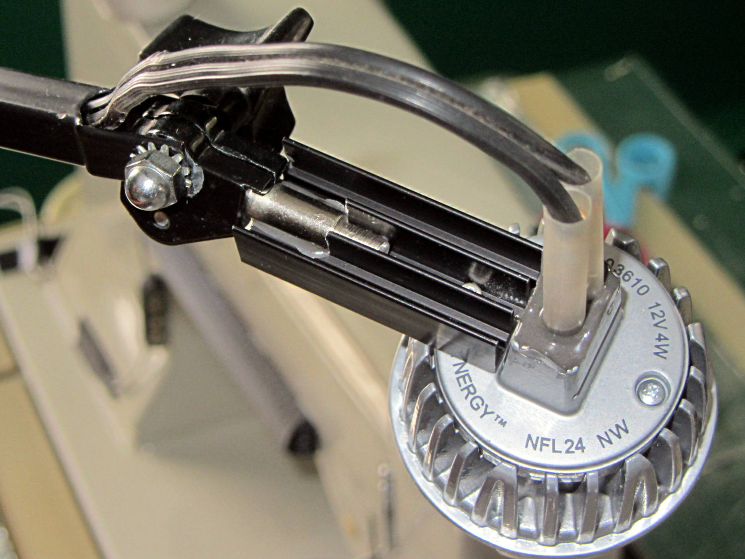
Shortly thereafter, I milled off the central fins to fit the shaft of the pivot screw, introduced the heatsink to Mr. Disk Sander to bevel the bottom, sawed the threads off the pivot, press-fit the two together, drilled a 2 mm cross-hole into the pivot, buttered it all up with epoxy, jammed a short M2 screw into the cross hole, and let the whole mess cure:
Desk Lamp LED Adapter – top view
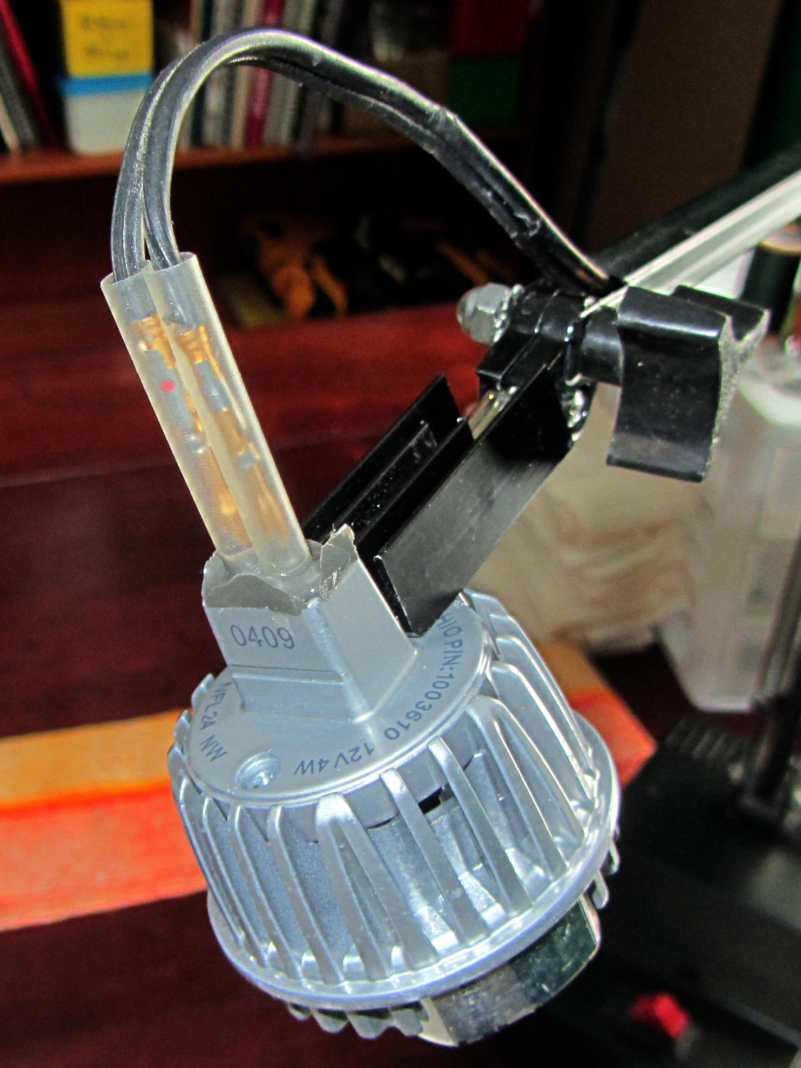
The lamp modules were a surplus find, with one pin clipped nearly flush to the insulator. I soldered a pair of the same male pins as in the battery holders, with the matching female pins as a crude connector. The unshrunk heatstink tubing isn’t lovely, but got us to First Light:
Desk Lamp LED Adapter – front view
The original counterweight is, of course, much too heavy for the dinky LED module, so I’ll drill the mounting hole for the vertical arm further back on the beam to get another foot of reach. That will require more wire between the transformer to the lamp, soooo the connectors might just become soldered joints.
As you can tell from the background, Mary snatched the lamp from my hands and put it to immediate use in The Quilting Room.
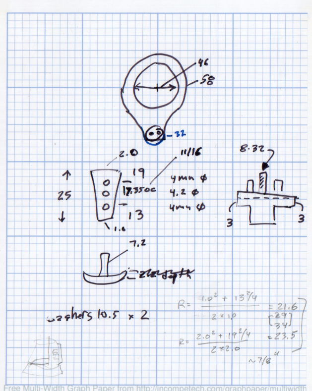
The original doodles bear no resemblance to the final product, but do have some key dimensions that (having discarded the unused hardware) I’ll likely never need again.
The pivot between the arm and the lamp housing, with an idea for the LED holder:
Desk Lamp Bracket Dimensions – doodle
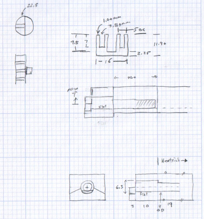
Details of the repurposed heatsink and the pivot bolt, with a block that never got built:
Although commenting out an undesired variable isn’t fashionable, OpenSCAD doesn’t have a practical mechanism to set specific values based on a control variable:
if-then-else deals with geometric objects
(boolean)?when_true:when_false (the ternary operator) doesn’t scale well
You could, of course, depend on OpenSCAD’s behavior of using the last (in syntactic order) instance of a “variable”, but IMHO that’s like depending on semantic whitespace.
In any event, the rest of the block builds itself around those three values by recomputing all of its dimensions.
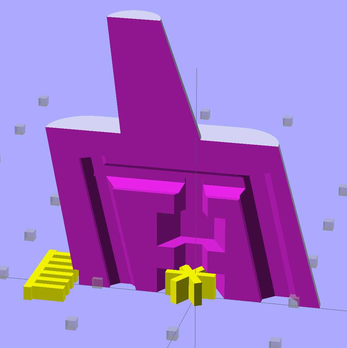
The Browning OEM block looks like this:
Browning Hi-Power Magazine Block – solid model – BHP OEM
The Generic floorplate has a much larger spring retaining crimp, so the block has far more overhang:
Browning Hi-Power Magazine Block – solid model – Generic 1
As before, the yellow widgets are built-in support structures separated from the main object by one thread thickness and width. That seems to maintain good vertical tolerance and allow easy removal; the structures snap free with minimal force. A closeup look shows the gaps:
Browning Hi-Power Magazine Block – solid model – Generic 1 – support detail
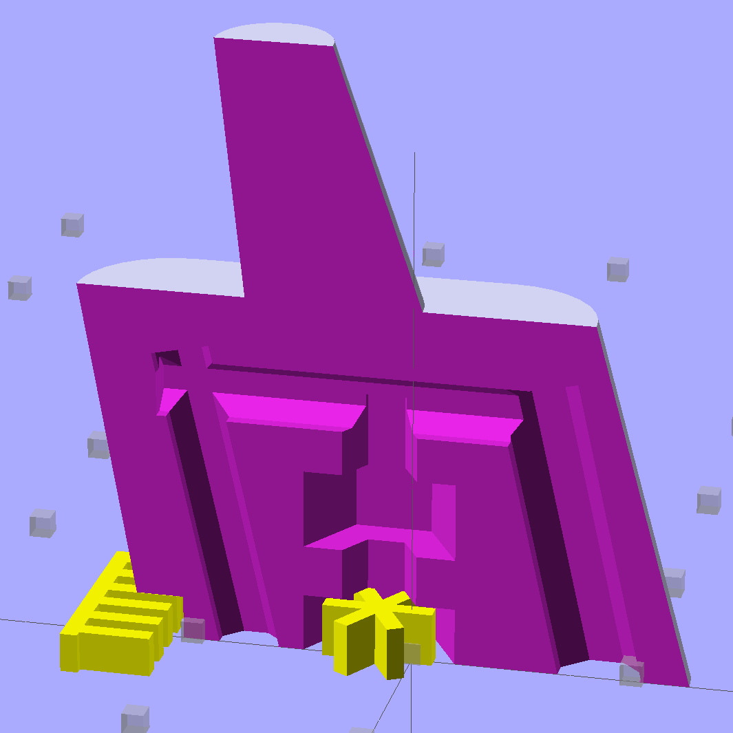
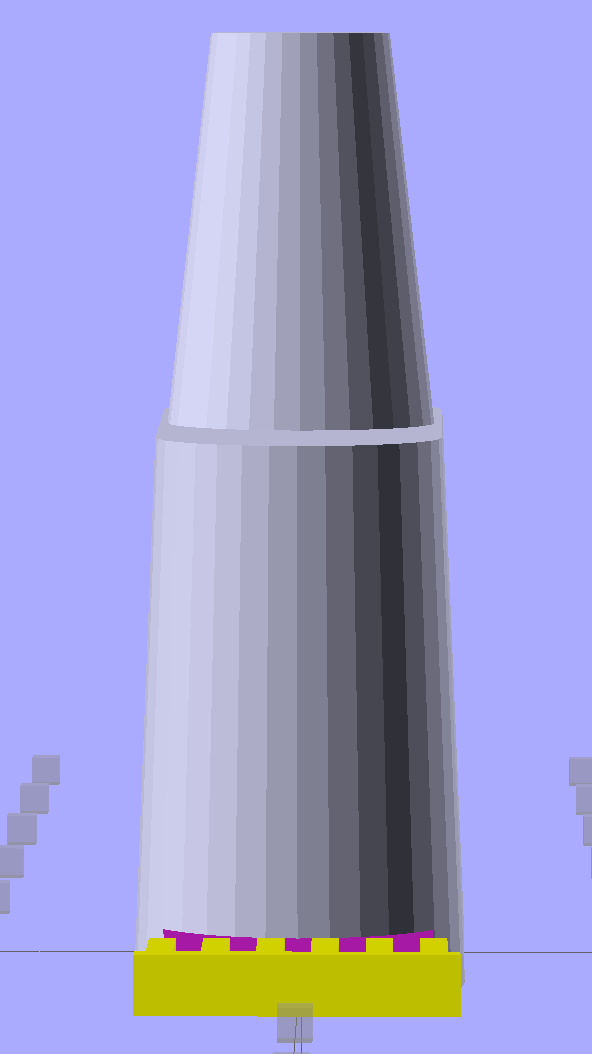
The main shape now has a 2 mm taper to ease the magazine spring past the upper edge of the block. The horn remains slightly inset from the side walls to ensure that the whole thing remains manifold:
Browning Hi-Power Magazine Block – solid model – Generic 1 – whole end
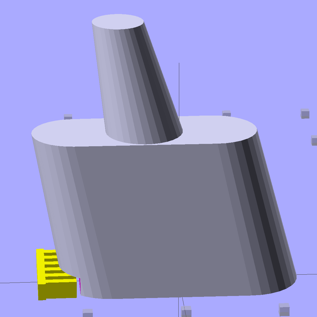
The whole object looks about the same, though:
Browning Hi-Power Magazine Block – solid model – Generic 1 – whole side
The shape descends from the geometry I used for the stainless steel block, with the additional internal channel (on the right in the models) to be filled with steel-loaded epoxy during assembly. That should make the whole block sufficiently robust that you must destroy the floorplate and distort the spring to get it out; wrecking the magazine’s innards should count as not “readily” modifiable.
Some destructive testing seems to be in order…
The OpenSCAD source code:
// Browning Hi-Power Magazine Plug
// Ed Nisley KE4ZNU December 2013
// February 2014 - easier customization for different magazine measurements
Layout = "Whole"; // Whole Show Split
// Whole = upright for steel or plastic
// Show = section view for demo, not for building
// Split = laid flat for plastic show-n-tell assembly
AlignPins = true && (Layout == "Split"); // pins only for split show-n-tell
Support = true && (Layout != "Split"); // no support for split, optional otherwise
// Define magazine measurements
//BlockData =  [-0.5, 1.5, 11.5];	// Browning OEM
BlockData = [-1.5, 2.0, 9.0];		// Generic 1

SCREWOFFSET = 0;
CRIMPHEIGHT = 1;
CRIMPDISTANCE = 2;
//- Extrusion parameters must match reality!
// Print with 2 shells and 3 solid layers
ThreadThick = 0.20;
ThreadWidth = 0.40;
HoleWindage = 0.2;
Protrusion = 0.1; // make holes end cleanly
function IntegerMultiple(Size,Unit) = Unit * ceil(Size / Unit);
//----------------------
// Dimensions
Angle = 12.5; // from vertical
SpringID = 10.3; // magazine spring curvature (measure with drill shank)
SpringRadius = SpringID / 2;
Taper = 2.0; // total taper toward top
Length = 24.5; // front-to-back perpendicular to magazine shaft
Height = 17.0; // bottom-to-top, parallel to magazine shaft
RectLength = Length - SpringID; // block length between end radii
HornBaseOD = 8.0; // fits between follower pegs to prevent shortening
HornTipOD = 5.0;
HornAddTip = (HornTipOD/2)*tan(Angle);
HornAddBase = (HornBaseOD/2)*tan(Angle);
HornAddLength = HornAddTip + HornAddBase + 2*Protrusion;
HornLength = 12.0; // should recompute ODs, but *eh*
ScrewOD = 3.0 - 0.25; // screw hole dia - minimal thread engagement
ScrewLength = Height - 5.0;
ScrewOffset = BlockData[SCREWOFFSET]; // ... from centerline on XY plane
NutOD = 5.8; // hex nut dia across flats
NutThick = 2.4; // ... generous allowance for nut
NutTrapLength = 1.5*NutThick; // allow for epoxy buildup
NutTrapBaseHeight = 5.0; // ... base height from floor plate
CrimpHeight = IntegerMultiple(BlockData[CRIMPHEIGHT],ThreadThick); // vertical clearance for spring crimp tab on base plate
CrimpDistance = BlockData[CRIMPDISTANCE]; // ... clip to screw hole center
CrimpOffset = -(CrimpDistance - ScrewOffset); // ... horizontal from centerline
SupportLength = 4.0; // length of support struts under Trim
SupportWidth = IntegerMultiple(0.9*SpringID,4*ThreadWidth); // ... size needed for platform adhesion
SupportThick = CrimpHeight - ThreadThick; // ... clearance for EZ removal
VentDia = 2.5; // air vent from back of screw recess
//VentOffset = CrimpOffset + VentDia/2 + 5*ThreadWidth;
VentOffset = -(NutOD + 4*ThreadWidth);
VentLength = ScrewLength + VentDia;
RecessDia = 3.5; // additional air vent + weight reduction
RecessLength = ScrewLength + RecessDia/2; // ... internal length
RecessOffset = Length/2 - RecessDia/2 - 5*ThreadWidth; // ... offset from centerline
PinOD = 1.72; // alignment pins
PinLength = 4.0;
PinInset = 0.6*SpringRadius; // from outside edges
echo(str("Alignment pin length: ",PinLength));
NumSides = 8*4; // default cylinder sides
Offset = 5.0/2; // from centerline for build layout
//----------------------
// Useful routines
function Delta(a,l) = l*tan(a); // incremental length due to angle
// Locating pin hole with glue recess
// Default length is two pin diameters on each side of the split
module LocatingPin(Dia=PinOD,Len=0.0) {
PinLen = (Len != 0.0) ? Len : (4*Dia);
translate([0,0,-ThreadThick])
PolyCyl((Dia + 2*ThreadWidth),2*ThreadThick,4);
translate([0,0,-2*ThreadThick])
PolyCyl((Dia + 1*ThreadWidth),4*ThreadThick,4);
translate([0,0,-(Len/2 + ThreadThick)])
PolyCyl(Dia,(Len + 2*ThreadThick),4);
}
module PolyCyl(Dia,Height,ForceSides=0) { // based on nophead's polyholes
Sides = (ForceSides != 0) ? ForceSides : (ceil(Dia) + 2);
FixDia = Dia / cos(180/Sides);
cylinder(r=(FixDia + HoleWindage)/2,
h=Height,
$fn=Sides);
}
module ShowPegGrid(Space = 10.0,Size = 1.0) {
Range = floor(50 / Space);
for (x=[-Range:Range])
for (y=[-Range:Range])
translate([x*Space,y*Space,Size/2])
%cube(Size,center=true);
}
//----------------------
// The magazine block
module Block(SectionSelect = 0) {
CropHeight = Height*cos(Angle); // block height perpendicular to base
echo(str("Perpendicular height: ",CropHeight));
difference() {
union() {
intersection() {
rotate([Angle,0,0])
hull() {
for (i=[-1,1])
translate([0,i*RectLength/2,-((Length/2)*sin(Angle) + Protrusion)])
cylinder(r1=SpringRadius,r2=(SpringRadius - Taper/2),
h=(Height + 2*(Length/2)*sin(Angle) + 2*Protrusion),
$fn=NumSides);
}
translate([0,0,CropHeight/2])
cube([2*SpringID,3*Length,CropHeight],center=true);
}
translate([0,-Height*sin(Angle),Height*cos(Angle)])
resize([(SpringID - Taper),0,0])
intersection() {
rotate([Angle,0,0])
translate([0,0,-(HornAddBase + Protrusion)])
cylinder(r1=HornBaseOD/2,
r2=HornTipOD/2,
h=(HornLength + HornAddLength + Protrusion),
$fn=NumSides);
cube([2*SpringID,Length,2*(HornLength*cos(Angle) + Protrusion)],center=true);
}
}
translate([0,ScrewOffset,-Protrusion]) // screw
rotate(180/6)
PolyCyl(ScrewOD,(ScrewLength + Protrusion),6);
translate([0,ScrewOffset,NutTrapBaseHeight]) // nut trap in center
rotate(180/6)
PolyCyl(NutOD,NutTrapLength,6);
translate([0,ScrewOffset,-Protrusion]) // nut clearance at base
rotate(180/6)
PolyCyl(NutOD,(1.1*NutThick + Protrusion),6);
translate([SpringID/2,CrimpOffset,-Protrusion])
rotate(180)
cube([SpringID,Length,(CrimpHeight + Protrusion)],center=false);
if (AlignPins) // alignment pins
if (true)
translate([0,-CropHeight*tan(Angle),CropHeight])
rotate([0,90,0]) rotate(45 + Angle)
LocatingPin(PinOD,PinLength);
else
for (i=[-1,1]) // cannot use these with additional vents * channels
rotate([Angle,0,0])
translate([0,
(i*((Length/2)*cos(Angle) - PinInset)),
(CropHeight/2 - i*2*PinInset)])
rotate([0,90,0]) rotate(45 - Angle)
LocatingPin(PinOD,PinLength);
translate([0,(ScrewOffset + 1.25*NutOD),ScrewLength]) // air vent
rotate([90,0,0]) rotate(180/8)
PolyCyl(VentDia,3*NutOD,8);
translate([0,VentOffset,-(VentDia/2)*tan(Angle)])
rotate([Angle,0,0]) rotate(180/8)
PolyCyl(VentDia,VentLength,8);
translate([0,RecessOffset,0]) // weight reduction recess
rotate([Angle,0,0]) rotate(180/8)
translate([0,0,-((RecessDia/2)*tan(Angle))])
PolyCyl(RecessDia,(RecessLength + (RecessDia/2)*tan(Angle)),8);
if (SectionSelect == 1)
translate([0*SpringID,-2*Length,-Protrusion])
cube([2*SpringID,4*Length,(Height + HornLength + 2*Protrusion)],center=false);
else if (SectionSelect == -1)
translate([-2*SpringID,-2*Length,-Protrusion])
cube([2*SpringID,4*Length,(Height + HornLength + 2*Protrusion)],center=false);
}
SupportSlots = (SupportWidth / (4*ThreadWidth)) / 2; // SupportWidth is multiple of 4*ThreadWidth
if (Support)
color("Yellow") {
translate([0,(CrimpOffset - SupportLength/2),SupportThick/2])
difference() {
translate([0,-ThreadWidth,0])
cube([(SupportWidth - Protrusion),SupportLength,SupportThick],center=true);
for (i=[-SupportSlots:SupportSlots])
translate([i*4*ThreadWidth + 0*ThreadWidth,ThreadWidth,0])
cube([(2*ThreadWidth),SupportLength,(SupportThick + 2*Protrusion)],center=true);
}
translate([0,ScrewOffset,0])
for (j=[0:5]) {
rotate(30 + 360*j/6)
translate([(NutOD/2 - ThreadWidth)/2,0,(1.1*NutThick - ThreadThick)/2])
color("Yellow")
cube([(NutOD/2 - ThreadWidth),
(2*ThreadWidth),
(1.1*NutThick - ThreadThick)],
center=true);
}
}
}
//-------------------
// Build it...
ShowPegGrid();
if (Layout == "Show")
Block(1);
if (Layout == "Whole")
Block(0);
if (Layout == "Split") {
translate([(Offset + Length/2),Height/2,0])
rotate(90) rotate([0,-90,-Angle])
Block(-1);
translate([-(Offset + Length/2),Height/2,0])
rotate(-90) rotate([0,90,Angle])
Block(1);
}
Some trial fitting with the prototype showed that there’s no possible way to route the connections through the socket, no matter how much I wanted that to happen, so I rotated the body to align the LEDs with the socket pin slots:
Sears Lamp LED Adapter – Show view
The body now builds with the flat end down, so the overall finish should be better:
Sears Lamp LED Adapter – Build view
A test run shows why I really, really wanted cool white LEDs in the strips over the arm:
Kenmore 158 Sewing Machine – mixed LED lighting
The LED mount doesn’t have quite enough room inside the end cap for the holder to tilt as I wanted; the two 10 mm LEDs can be about 10 mm lower and slightly closer to the shaft driving the needle, which is what this rapid prototyping stuff is all about. Scrapping the existing lamp socket and (120 VAC!) wiring seems the best way to make this more useful.
Early reports on the arm LEDs indicate a requirement for more light, so the next iteration of those mounts will put two strips side-by-side…
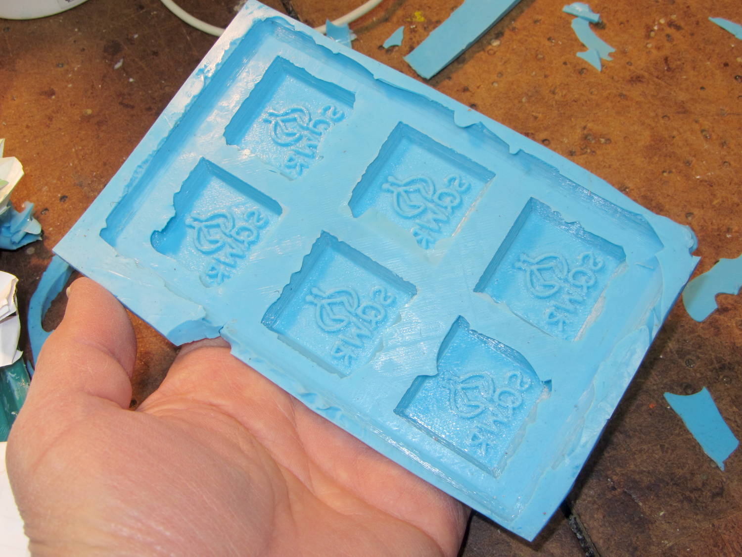
A closeup shows that the characteristic 3D printed striations came through perfectly on the silicone:
SqWr chocolate molds – silicone interior detail
In this application, the 3D printer’s hand-knitted look is desirable, but most molds would benefit from manual smoothing / sanding / filling; perhaps slathering release agent over the molds would help. In any event, the silicone didn’t lock to the striations and parted easily, so it’s all good.
The first layer of silicone worked its way between the positive molds and the slab; Tesa says the positives were so well attached to the pegs that she forgot to apply double-sided tape between them. No harm done: the flashing peeled / trimmed off easily enough.
She thinks a shallow block mold would work just as well for a slab like this: you’d (well, she’d) save hours of tedious layering. The block mold wouldn’t use any more silicone, as the mixing cup had plenty of residue after each layer, even after scraping: doing just one mixing, one pouring, and one curing stage would be a major win.
Something Went Wrong during the elaborate dance my M2 goes through to home all three axes, resulting in the platform heater connector whacking the nozzle from the rear, the nozzle dragging off the platform to the right, and then jamming on the edge of the too-high platform on the way back. As nearly as I can tell, the command to lower the platform before doing anything else didn’t happen, after which things slid rapidly downhill.
There are disadvantages to having powerful motors and rigid machinery, but in this case the advantages outweigh them. You should browse Youtube’s collection of CNC mishaps to see what a real machine tool crash looks like.
I think that’s the second time the thing has misbehaved, so it’s doing OK. I have seen a few instances where the firmware doesn’t obey the acceleration limits, but I don’t have any way to verify what happened. If the Z-axis motor stalled while lowering the platform, that would explain everything; that same G-Code has worked flawlessly for nearly a year.
After realigning the extruder motor and checking that the hot end hadn’t gotten dislodged, I ran off a thinwall open box that showed the extruder was about 0.1 mm lower than before. That called for a tweak to the G92 setting in the startup G-Code that defines the offset between the two.
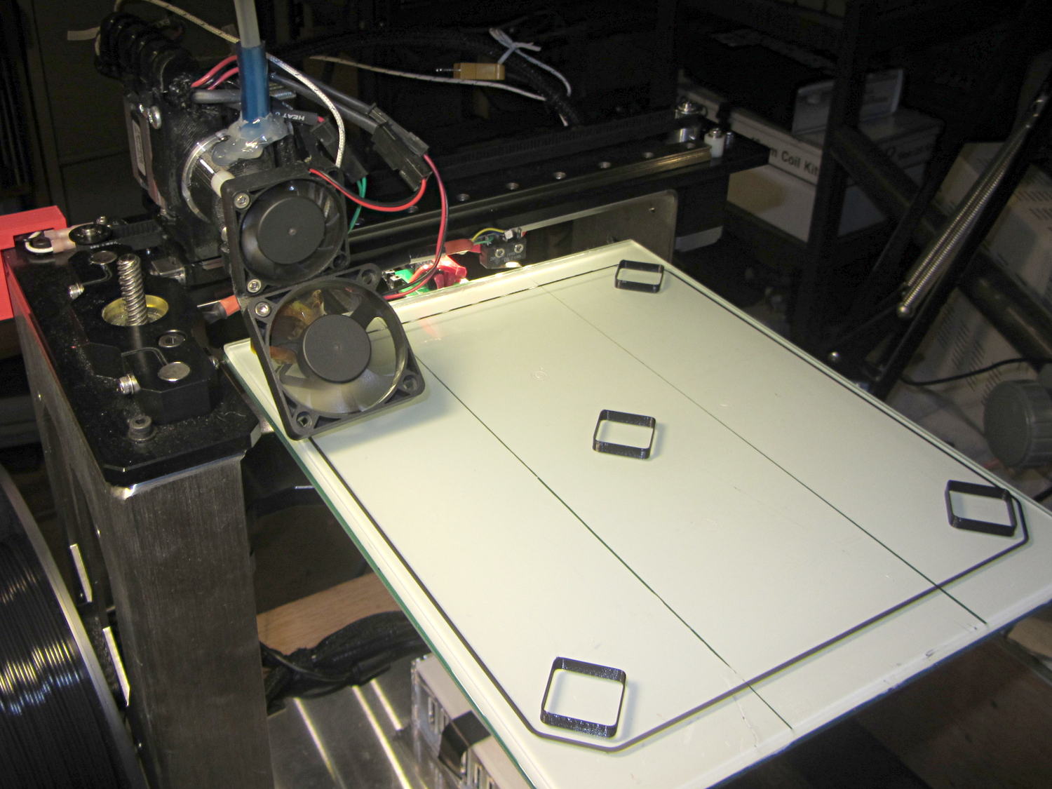
After that, I figured it would be a Good Idea to check the platform leveling, so I arranged five boxes on the platform:
M2 Platform Leveling – thinwall open box layout
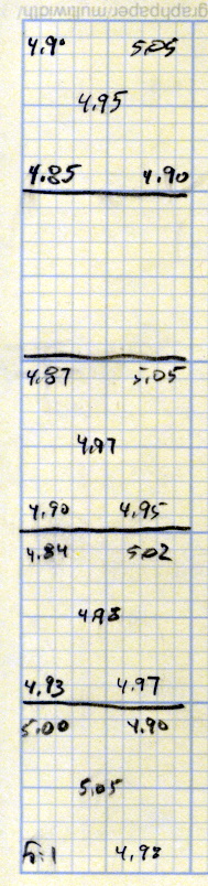
About 8 minutes later, I had the five values at the top of this scratch paper:
M2 Platform Leveling Data
Tweaking the three leveling screws under the platform and iterating with more boxes eventually got the platform aligned to about ±0.07 mm across the 200×250 mm platform diagonal; supper got in the way of repeating the last test. The bird’s nest failure of the left-front box in that test looked like an adhesion problem; in the heat of it all, I built four sets of thinwall boxes on exactly the same spots without renewing the hairspray coating.
Measuring the skirt and box heights suggested a bit of adjustment to the initial Z offset. A static measurement comes pretty close, but the actual results are what matters.
I’ll recheck the alignment at some point, but for now it’s back in operation…
The current startup G-Code from Slic3r’s configuration:
;-- Slic3r Start G-Code for M2 starts --
;  Ed Nisley KE4NZU - 15 Nov 2013
;  28 Feb 2014 tweak Z offset
; Z-min switch at platform, must move nozzle to X=130 to clear
M140 S[first_layer_bed_temperature]	; start bed heating
G90				; absolute coordinates
G21				; millimeters
M83				; relative extrusion distance
G92 Z0			; set Z to zero, wherever it might be now
G1 Z10 F1000	; move platform downward to clear nozzle; may crash at bottom
G28 Y0			; home Y to be sure of clearing probe point
G92 Y-127 		; set origin so 0 = center of plate
G28 X0			; home X
G92 X-95		; set origin so 0 = center of plate
G1 X130 Y0 F30000	; move off platform to right side, center Y
G28 Z0			; home Z with switch near center of platform
G92 Z-4.40		; set origin to measured z offset
G0 Z2.0			; get air under switch
G0 Y-127 F10000	; set up for priming, zig around corner
G0 X0			;  center X
M109 S[first_layer_temperature]	; set extruder temperature and wait
M190 S[first_layer_bed_temperature]	; wait for bed to finish heating
G1 Z0.0 F500	; plug extruder on plate
G1 E25 F300		; prime to get pressure, generate blob
G1 Z5 F2000		; rise above blob
G1 X15 Y-125 F30000	; jerk away from blob, move over surface
G1 Z0.0 F1000	; dab nozzle to attach outer snot to platform
G4 P1			; pause to attach
G1 X35 F500		; slowly smear snot to clear nozzle
G1 Z1.0 F2000	; clear bed for travel
;-- Slic3r Start G-Code ends --