The general idea is that the extruder motor mount will clamp the exceedingly smooth and totally featureless circumference of the motor gearbox:
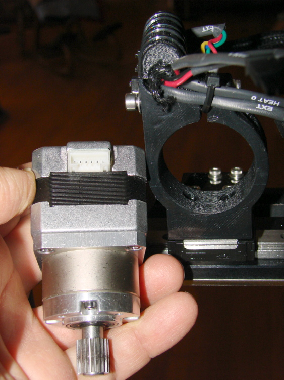
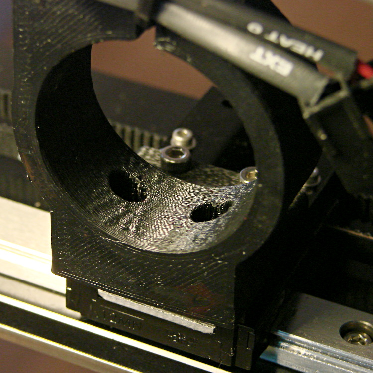
The as-built interior of the circumferential clamp has enough ripples and ridges and imperfections that it can’t get a solid grip on the metal gearbox:
That allows the motor to rotate slightly in the mount, with what seemed like very little torque, and misalign the extruder nozzle with respect to the platform. There’s about 80 mm between the motor shaft and the nozzle, so a mere 4° tilt raises the nozzle an additional 0.1 mm, entirely enough to throw off the Z axis height setting.
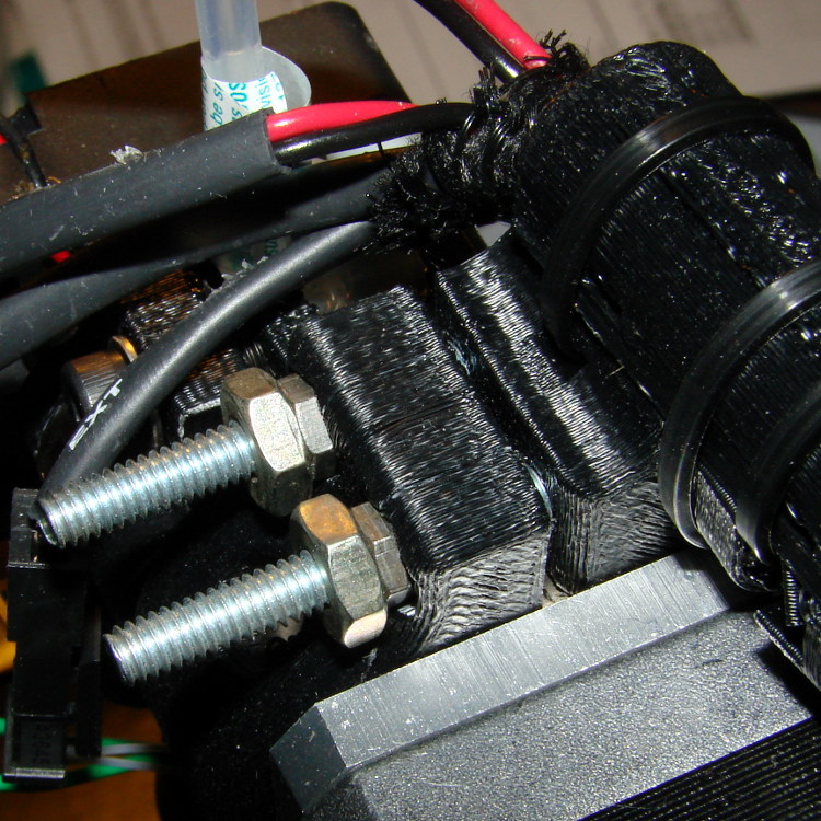
I smoothed the worst of the bumps with a file and applied a generous dose of rosin for a better grip. Two Nylock nuts sunk into the motor mount anchor a pair of M4 screws that compress the circumferential clamp around the motor, but there’s not enough plastic around them for proper support and the mount promptly cracked in exactly the places you’d expect. I reamed out the holes to pass overly long 10-32 pan-head screws, scraped out the nut traps to accept 10-32 nuts, then added two small nuts and a large jam nut to each one:
That’s a temporary expedient until I rebuild the entire mount, as the plastic remains split and the clamp isn’t applying uniform pressure to the gearbox.
The extruder motor mount on my M2 doesn’t match the drawings: it seems Makergear changed from a one-piece extruder motor mount (which required slipping the extruder cable loom and connectors through a tunnel above the motor) to a two-piece design (which clamps the cable between two U-shaped strips). Unfortunately, there’s simply not enough plastic to provide sufficient strength in several vital sections; the nuts just described being one.
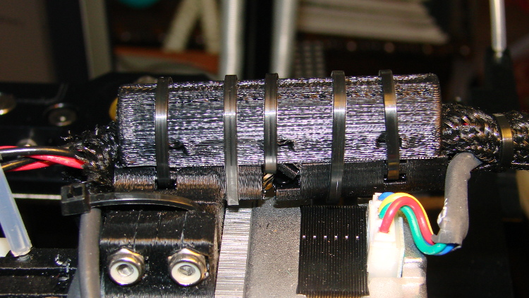
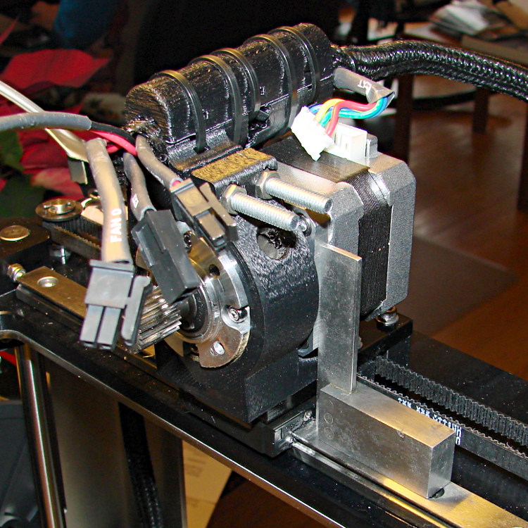
More conspicuously, the lower U-shaped cable clamp strip cracked just behind the motor clamp body, because the plastic filaments run across the mount, perpendicular to the direction of maximum stress and have very little cross-sectional area. I applied extra cable ties on both sides of the fracture, so that the top strip serves as splint for the lower:
That photo shows the M4 Nylock nuts splitting the mount prior to the 10-32 screw fix.
The wire loom evidently corresponds to the previous mount design, as there’s not enough slack in the thermistor and heater cables to mate the connectors. I trimmed off some loom and rerouted the wires appropriately:

With all that in hand, a tiny machinist’s square aligned the motor with the X axis slide and set the extruder perpendicular to the platform:
I’m unhappy with how that worked out, but it’s good enough for now. I think rebuilding the mount in aluminum will work better for what I have in mind; this seems to be one of the places where 3D printed plastic isn’t quite appropriate.

Comments
3 responses to “Makergear M2: Extruder Motor Mount”
I’d wonder if the printed motor mount would have been better used as the pattern for a cast aluminum mount. Yet Another Technology, but a cast mount would be easier to finish (I’d hope) than starting with a cube of aluminum, and you’d avoid woodgrain type problems…
(Side note: I once caught a small presentation on lost-foam casting. Similar to lost wax, but the core gets evaporated in the casting process rather than baked out. Bing searching shows some folks using drywall compound as an investment medium. I had heard GM did a variant with loose sand for Saturn blocks, but I suspect that’s a process that needs really close control of too many parameters… Still, one wonders about a 3D printer nozzle that shoots foam filaments for prototypes. At least one maniac uses polyurethane foam as a core.)
Dunno. Add in the overhead of doing an aluminum casting and I’m not sure it’s a net win. I’d start with a plate about the right thickness and whittle bits off it until it was the right shape; most of the protrusions can be bolted or epoxied in place. I think so, anyway.
I’ve toted a gas-fired crucible furnace through three states without lighting it up. One Of These Days …
[…] realigning the extruder motor and checking that the hot end hadn’t gotten dislodged, I ran off a thinwall open box that […]