Ed Nisley's Blog: Shop notes, electronics, firmware, machinery, 3D printing, laser cuttery, and curiosities. Contents: 100% human thinking, 0% AI slop.
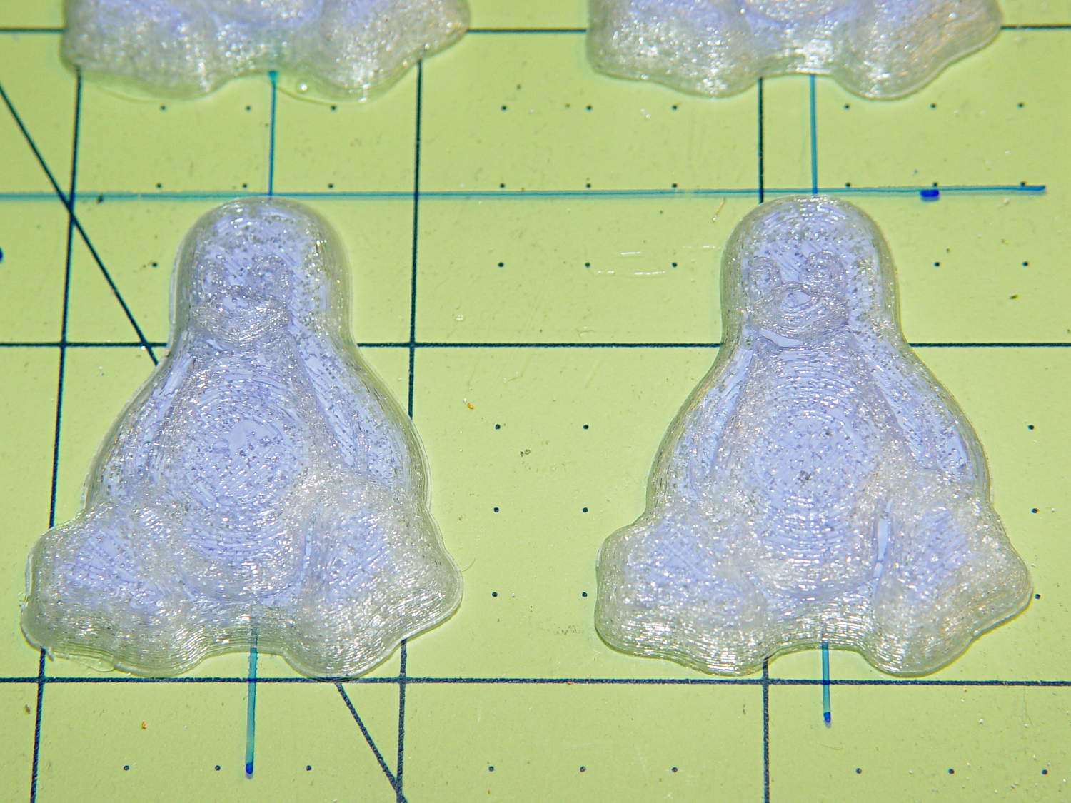
Seeing as how the Tux chocolates were produced in a facility containing a big nut, some folks may prefer an (inedible, at least by humans, but correspondingly more permanent) Tux tchotchke in PLA. I plan to have the M2 running off more of them, so there should be enough to go around.
For what it’s worth, you can actually buy a 3D chocolate printer that seems rather overpriced for what’s basically a desktop CNC gantry mill with a heated syringe. The site seems dead, so maybe other folks came to that conclusion, too.
Some pix that serve as a stick in the ground showing that my current Slic3r configuration constellation doesn’t produce thin infill…
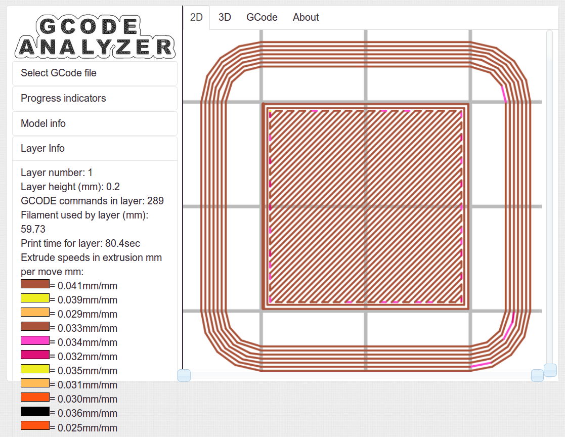
All of the layers in the 20 mm calibration cube look just like this:
Solid cube – Slic3r normal infill
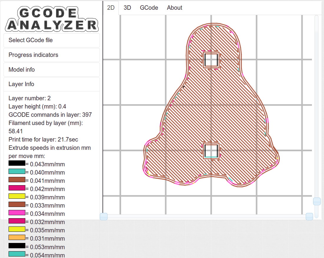
The bottom layer of the Tux mold comes out solid:
Tux thread fill – bottom
As does the top:
Tux thread fill – top
The Gcode Analyzeralgorithm that assigns colors to numeric values tends to produce many aliases, although most of the time you can figure out what’s going on. If somebody wants to dive into the code, I’d like to have unique colors and get the color table sorted in ascending order.
The current Slic3r configuration:
# generated by Slic3r 1.1.1 on Sat May  3 10:31:36 2014
avoid_crossing_perimeters = 0
bed_size = 190,250
bed_temperature = 70
bottom_solid_layers = 3
bridge_acceleration = 0
bridge_fan_speed = 100
bridge_flow_ratio = 1
bridge_speed = 150
brim_width = 0
complete_objects = 0
cooling = 1
default_acceleration = 0
disable_fan_first_layers = 1
duplicate_distance = 6
end_gcode = ;-- Slic3r End G-Code for M2 starts --\n;  Ed Nisley KE4NZU - 15 November 2013\nM104 S0		; drop extruder temperature\nM140 S0		; drop bed temperature\nM106 S0		; bed fan off\nG1 Z180 F2000	; lower bed\nG1 X130 Y125 F30000	; nozzle to right, bed front\nM84     	; disable motors\n;-- Slic3r End G-Code ends --
external_perimeter_speed = 25
external_perimeters_first = 0
extra_perimeters = 1
extruder_clearance_height = 25
extruder_clearance_radius = 15
extruder_offset = 0x0
extrusion_axis = E
extrusion_multiplier = 1.07
extrusion_width = 0.4
fan_always_on = 0
fan_below_layer_time = 30
filament_diameter = 1.79
fill_angle = 45
fill_density = 100%
fill_pattern = rectilinear
first_layer_acceleration = 0
first_layer_bed_temperature = 70
first_layer_extrusion_width = 0.4
first_layer_height = 100%
first_layer_speed = 25
first_layer_temperature = 175
g0 = 0
gap_fill_speed = 50
gcode_arcs = 0
gcode_comments = 0
gcode_flavor = reprap
infill_acceleration = 0
infill_every_layers = 3
infill_extruder = 1
infill_extrusion_width = 0
infill_first = 1
infill_only_where_needed = 0
infill_speed = 150
interface_shells = 0
layer_gcode =
layer_height = 0.2
max_fan_speed = 100
min_fan_speed = 75
min_print_speed = 4
min_skirt_length = 15
notes =
nozzle_diameter = 0.35
only_retract_when_crossing_perimeters = 1
ooze_prevention = 0
output_filename_format = [input_filename_base].gcode
overhangs = 1
perimeter_acceleration = 0
perimeter_extruder = 1
perimeter_extrusion_width = 0.4
perimeter_speed = 150
perimeters = 2
post_process =
print_center = 0,0
raft_layers = 0
randomize_start = 1
resolution = 0.05
retract_before_travel = 1
retract_layer_change = 0
retract_length = 1
retract_length_toolchange = 5
retract_lift = 0
retract_restart_extra = 0
retract_restart_extra_toolchange = 0
retract_speed = 60
skirt_distance = 3
skirt_height = 1
skirts = 3
slowdown_below_layer_time = 20
small_perimeter_speed = 25
solid_fill_pattern = rectilinear
solid_infill_below_area = 5
solid_infill_every_layers = 0
solid_infill_extrusion_width = 0
solid_infill_speed = 150
spiral_vase = 0
standby_temperature_delta = -5
start_gcode = ;-- Slic3r Start G-Code for M2 starts --\n;  Ed Nisley KE4NZU - 15 Nov 2013\n;  28 Feb 2014 - 6 Mar 2014 - tweak Z offset\n; Z-min switch at platform, must move nozzle to X=130 to clear\nM140 S[first_layer_bed_temperature]	; start bed heating\nG90				; absolute coordinates\nG21				; millimeters\nM83				; relative extrusion distance\nG92 Z0			; set Z to zero, wherever it might be now\nG1 Z10 F1000	; move platform downward to clear nozzle; may crash at bottom\nG28 Y0			; home Y to be sure of clearing probe point\nG92 Y-127 		; set origin so 0 = center of plate\nG28 X0			; home X\nG92 X-95		; set origin so 0 = center of plate\nG1 X130 Y0 F30000	; move off platform to right side, center Y\nG28 Z0			; home Z with switch near center of platform\nG92 Z-4.40		; set origin to measured z offset\nG0 Z2.0			; get air under switch\nG0 Y-127 F10000	; set up for priming, zig around corner\nG0 X0			;  center X\nM109 S[first_layer_temperature]	; set extruder temperature and wait\nM190 S[first_layer_bed_temperature]	; wait for bed to finish heating\nG1 Z0.0 F500	; put extruder near plate \nG1 E25 F300		; prime to get pressure, generate blob\nG1 Z5 F2000		; rise above blob\nG1 X15 Y-125 F20000	; jerk away from blob, move over surface\nG1 Z0.0 F1000	; dab nozzle to attach outer snot to platform\nG4 P1			; pause to attach\nG1 X35 F500		; slowly smear snot to clear nozzle\nG1 Z1.0 F2000	; clear bed for travel\n;-- Slic3r Start G-Code ends --
start_perimeters_at_concave_points = 1
start_perimeters_at_non_overhang = 1
support_material = 0
support_material_angle = 0
support_material_enforce_layers = 0
support_material_extruder = 1
support_material_extrusion_width = 0
support_material_interface_extruder = 1
support_material_interface_layers = 0
support_material_interface_spacing = 0
support_material_pattern = honeycomb
support_material_spacing = 2.5
support_material_speed = 150
support_material_threshold = 0
temperature = 175
thin_walls = 1
threads = 2
toolchange_gcode =
top_infill_extrusion_width = 0.4
top_solid_infill_speed = 25
top_solid_layers = 3
travel_speed = 250
use_firmware_retraction = 0
use_relative_e_distances = 0
vibration_limit = 0
wipe = 0
z_offset = 0
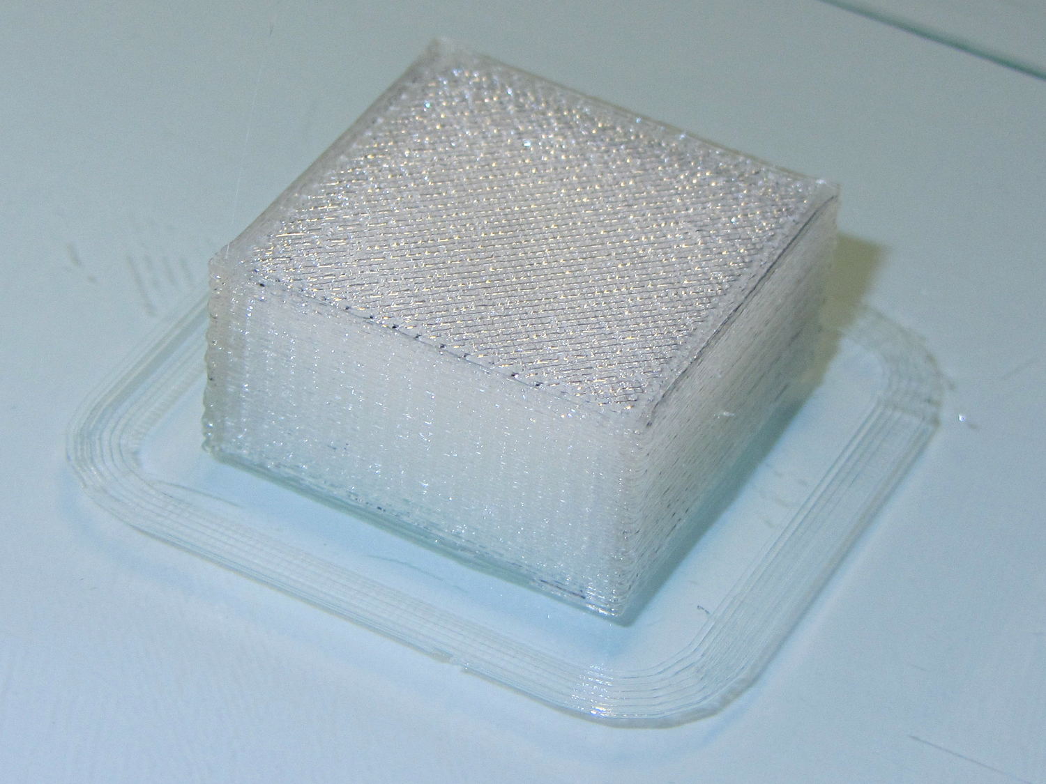
Having discovering that the chocolate mold positives suffered from sparse top infill, to the extent that silicone rubber would flow right though the surface…
Not only were the infilled surfaces porous, I could see right through the block! That’s impossible to photograph, but here’s a laser beam shining through the entire 10 mm stack, showing how precisely the M2 aligns 50 under-filled thread layers:
Solid cube – laser transmission
The yellow spot in the middle marks the overexposed laser beam. There’s a distinct beam passing through the block that, with the proper orientation, can create a spot on the cutting mat atop my desk.
In fact, I can blow air through the blocks; one could use them as (rather coarse) air filters.
Normally, underfill happens when a mechanical problem prevents the printer from feeding enough filament to keep up with demand, but that’s not the case here: the perimeter threads came out exactly 0.4 mm wide for the entire height of the cube, as you can see if you click the picture for more dots. The top and bottom infill, plus all the interior threads, seem to be about half the nominal width and don’t touch their neighbors on the same XY plane at all.
The colors show the length of extruder filament per millimeter of XY motion, not the usual XY speed, with the two perimeter threads at 0.033 mm/mm and the interior at 0.18 mm/mm. In round numbers, the G-Code starves the infill by a factor of 1.8, which is close enough to the factor of two I’d guessed going into this mess.
Being that type of guy, I set the exact extrusion thickness and width (0.20 x 0.40 mm), rather than let Slic3r pick them. The extruded thread has a fixed cross-section of (roughly) 0.080 mm2 and a millimeter of XY motion thus requires 0.080 mm3 of filament.
The PLA filament measures 1.79 mm diameter, for a cross-section of 2.5 mm2. Getting 0.080 mm3 from the incoming filament requires feeding 0.032 mm into the extruder, which is almost exactly what you see for the perimeter threads.
After restoring Slic3r’s default configuration, the problem Went Away, which suggests that I backed the algorithms into a corner with some perverse combination of settings. Rebuilding my usual configuration from the defaults also worked fine, so it’s obviously not Slic3r’s problem.
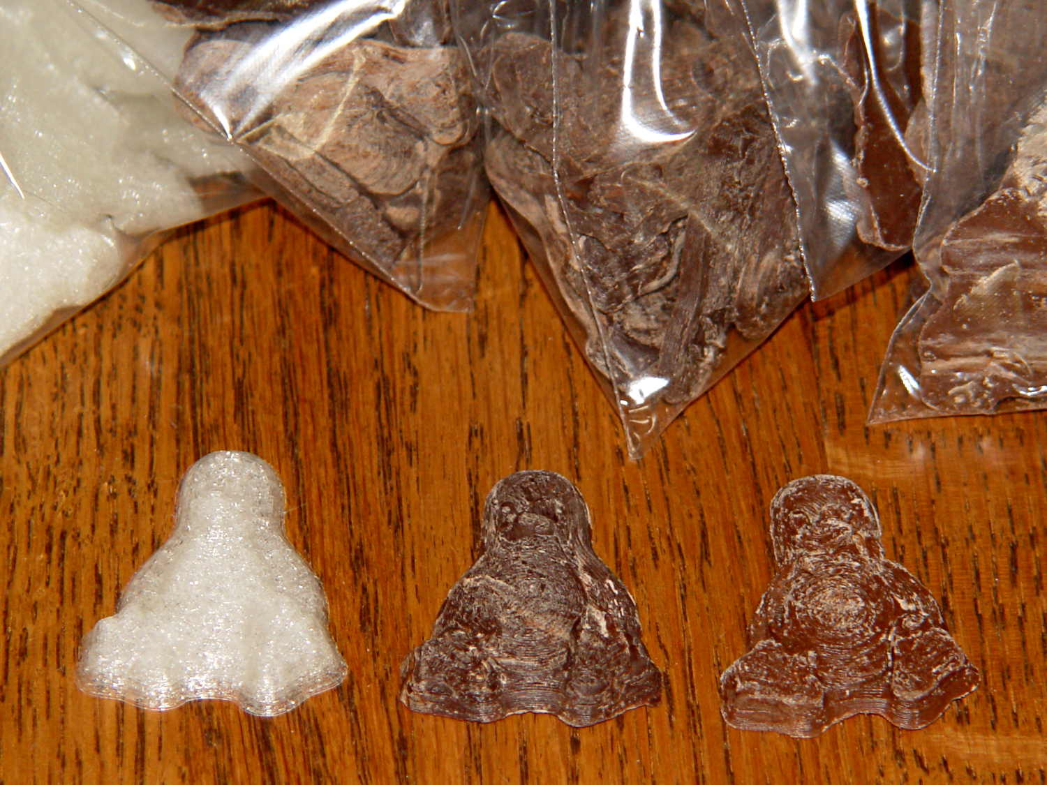
Which one is not like the other ones?
Solid cube tests
You can see the thin infill on three of those cubes, with the solid one in the lower right showing how it should look.
The solid cube weighs 4.4 g and the thin-fill variations weigh 2.7 to 2.9 g. Assuming PLA density = 1.25 g/cm3 and “cube” volume = 4 cm3, a completely solid cube should weigh 5.0 g. I think 4.4 g is close enough; the top surface came out flat with nice adjacent-thread fusion. Working backwards, the average fill = 88%; the perimeter is fused-glass solid, so the actual infill will be a bit under that.
I generally run Slic3r from my desktop box, with ~/.Slic3r symlinked to the actual config directory and its files on the NFS server downstairs. Perhaps running different versions of Slic3r on two or three different boxes, all using the same config files, wrecked something that didn’t show up in the UI and produced bad slices. I probably ran two different versions of Slic3r at the same time against the same files, although I wasn’t simultaneously typing at both keyboards.
Moral of the story: check the G-Code before assuming a hardware failure!
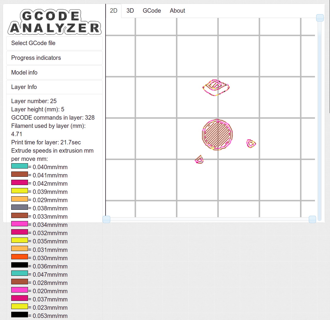
The latter, of course: I blundered the inner corner radius, which occasionally produced little tiny dots of infill that shouldn’t be there. Just one of those errors that hides in plain sight until something else goes wrong, then it’s obvious.
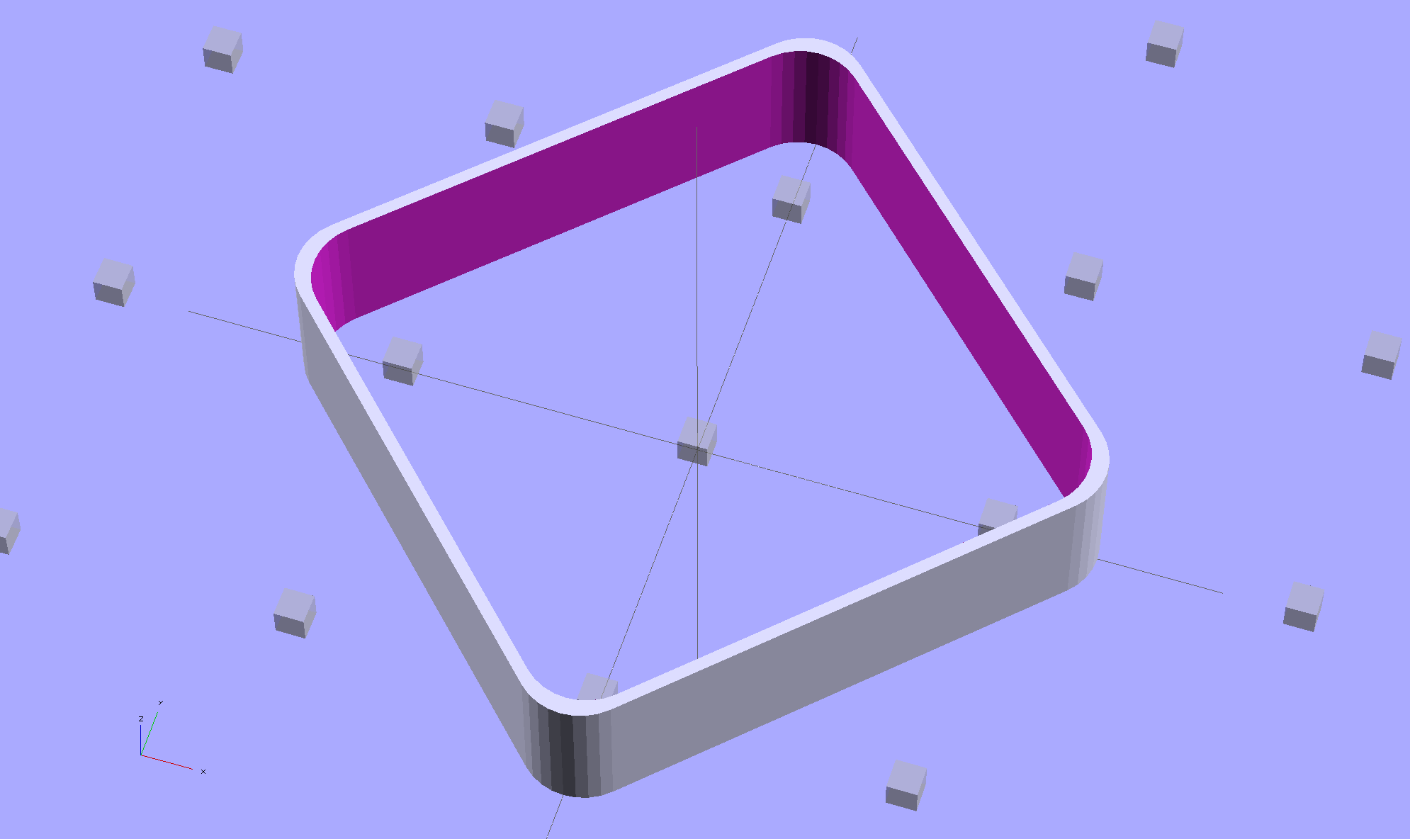
Rather than fix the Minkowski version, I rebuilt it using the hull() operator to shrinkwrap four cylinders for each solid, then remove the smaller block from the larger. Commenting out the hull() operators shows that the cylinders now line up properly:
Thinwall Open Box – un-hulled – solid model
The OpenSCAD source code:
// Thin wall open box calibration piece
// Adapted from Coasterman's Calibration set
// Ed Nisley - KE4ZNU - Dec 2011
// Adjust for Slic3r/M2 - March 2013
// Reworked for hull() with correct corner radii - April 2014

//-------
//- Extrusion parameters must match reality!
//  None of the fill parameters matter

ThreadThick = 0.20;
ThreadWidth = 0.40;

Protrusion = 0.1;           // make holes end cleanly

function IntegerMultiple(Size,Unit) = Unit * ceil(Size / Unit);

//-------
// Dimensions

Height = IntegerMultiple(5.0,ThreadThick);

WallThick = ThreadWidth;

CornerRadius = 2.0;
CornerSides = 4*8;

SideLen = 20.0 - 2*CornerRadius;

Rotation = 45;

//-------

module ShowPegGrid(Space = 10.0,Size = 1.0) {

  Range = floor(50 / Space);

    for (x=[-Range:Range])
      for (y=[-Range:Range])
        translate([x*Space,y*Space,Size/2])
          %cube(Size,center=true);
}

//-------

ShowPegGrid();

rotate(Rotation)
	difference() {
		hull() {
			for (i=[-1,1], j=[-1,1])
				translate([i*SideLen/2,j*SideLen/2,0])
					cylinder(r=CornerRadius,h=Height,$fn=CornerSides);
		}
		hull() {
			for (i=[-1,1], j=[-1,1])
				translate([i*SideLen/2,j*SideLen/2,-Protrusion])
					cylinder(r=(CornerRadius - WallThick),h=(Height + 2*Protrusion),$fn=CornerSides);
		}
	}
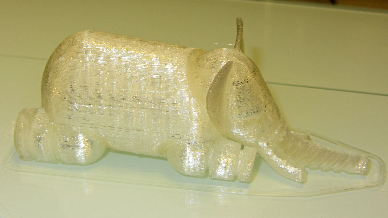
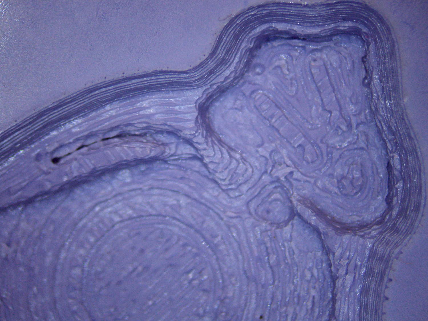
The PLA positive, after removing the silicone negative, showing the silicone below the surface:
Tux Gradient – PLA positive detail
The corresponding silicone negative cavity, flipped top-to-bottom:
Tux Gradient – silicone negative detail
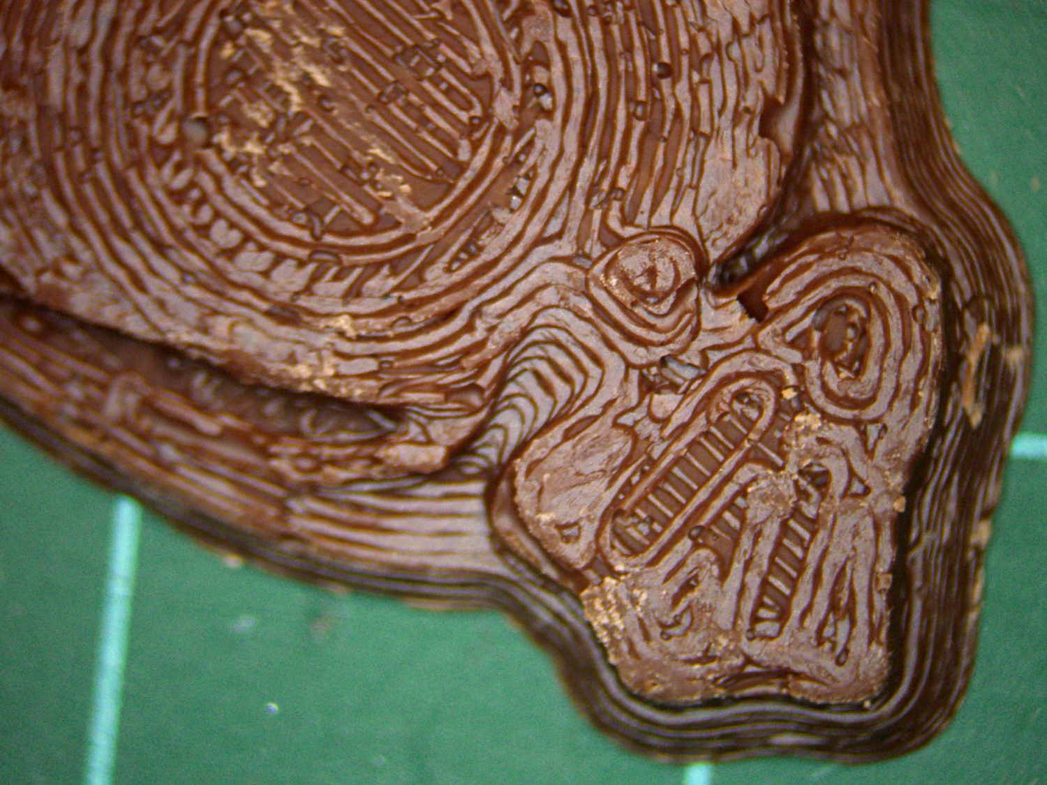
The milk chocolate result, although probably not from the same cavity:
Tux Gradient – milk chocolate detail
The radial gradient on the tummy comes through clearly and, I think, pleasingly, even though it’s only a few layers tall. The threads defining the flipper just above (to the left, in these images) of the foot show where the flipper crosses the tummy and foot level. I didn’t expect the foot webbing grooves to get that ladder-like texture, but I suppose having non-slip foot treads would be an advantage.
If you don’t mind the hand-knitted texture, which I don’t, this process seems perfectly workable.
Although directly printing the 2×2 molds worked reasonably well, that does not scale to larger arrays, because OpenSCAD doesn’t handle the profusion of vertices with any grace. Duplicating the STL file created from the height map image, however, isn’t a problem:
Tux-Gradient – Slic3r layout
I actually did it in two passes: 4 molds to be sure they’d come out right, then another dozen. Figure a bit under two hours for the lot of them, no matter how you, ah, slice it.
A grid drawn directly on 1/16 inch = 1.5 mm acrylic sheet guided the layout:
Tux Gradient 4×4 – mold as-cast
I anointed the back of each mold positive with PVC pipe cement, the version with tetrahydrofuran to attack the PLA and acetone/MEK to attack the acrylic, lined it up, and pressed it in place. The positives have recesses for alignment pins, but even I think that’s overkill in this application.
Memo to Self: Flip the acrylic over before gluing, so the guide lines wipe neatly off the bottom.
Tape a cardboard frame around the acrylic, mix & pour the silicone, put it on the floor to ensure it’s level (unlike our kitchen table), wait overnight for the cure, then peel positive and negative apart:
Tux Gradient 4×4 – mold separated
As before, the top surface of the positives isn’t watertight, so the silicone flowed through into the molds. This isn’t a simple extruder calibration issue, because the thinwall boxes are spot on, all the exterior dimensions are accurate, and everything else seems OK. What’s not OK is that threads on the top and (now that I look at it) bottom surfaces aren’t properly joining.
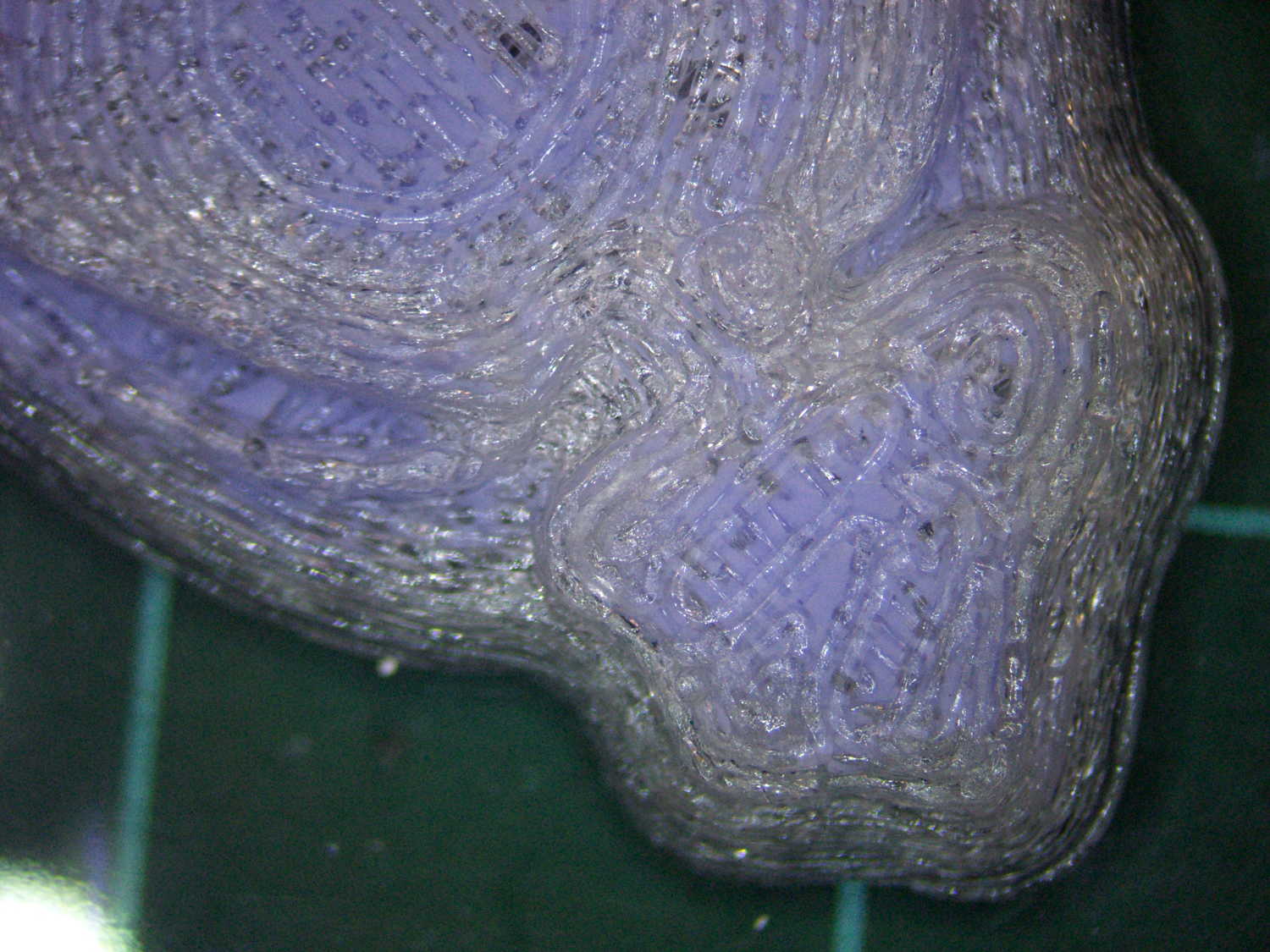
A closeup of the positive shows silicone between the threads and under the surface:
Tux Gradient 4×4 – postive detail
But the negative silicone looks just fine, in the usual hand-knitted way of all 3D printed parts:
Tux Gradient 4×4 – negative detail
Definitely fewer bubbles than before, although the flange between the flippers (wings? whatever) and the body isn’t as clean as it could be. Doing better may require pulling a vacuum on the silicone, which would mean the positives really must be air-tight solids.
Anyhow, the acrylic base produced a wonderfully flat surface that should make it a lot easier to run a scraper across the chocolate to remove the excess. Not that excess chocolate is ever a problem, but it’s the principle of the thing.