Some trial fitting with the prototype showed that there’s no possible way to route the connections through the socket, no matter how much I wanted that to happen, so I rotated the body to align the LEDs with the socket pin slots:
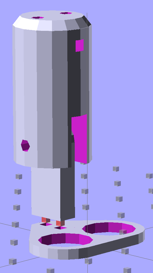
The body now builds with the flat end down, so the overall finish should be better:
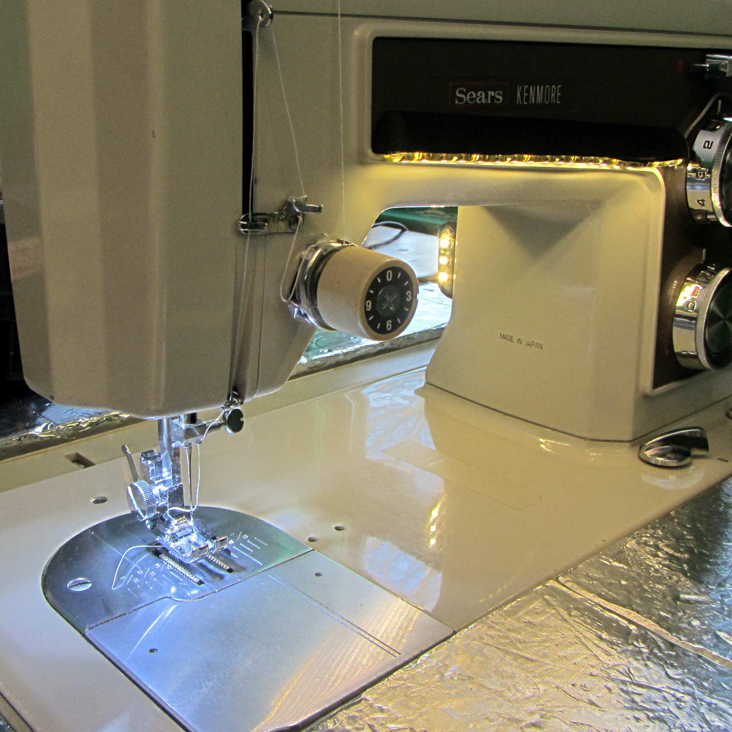
A test run shows why I really, really wanted cool white LEDs in the strips over the arm:
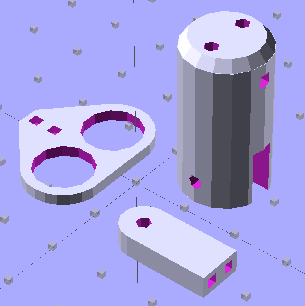
The LED mount doesn’t have quite enough room inside the end cap for the holder to tilt as I wanted; the two 10 mm LEDs can be about 10 mm lower and slightly closer to the shaft driving the needle, which is what this rapid prototyping stuff is all about. Scrapping the existing lamp socket and (120 VAC!) wiring seems the best way to make this more useful.
Early reports on the arm LEDs indicate a requirement for more light, so the next iteration of those mounts will put two strips side-by-side…

Comments
4 responses to “Sewing Machine Bulb Replacement: First (LED) Light!”
Want MOAR light? I got some of these things (the 12v ~ 14v @ 900mA version):
http://cgi.ebay.com/ws/eBayISAPI.dll?ViewItem&item=321346804545
They are a bunch of LED dies bonded to an aluminum PCB.
I mounted 4 of them around my welding helmet so my old eyes can see before the arc starts. They push out a lot of light. Very difficult to look at them.
I just have them running in free air for about 1/2 the other 1/2 double-sided taped to the helmet. They don’t smoke. I supposed that they should be mounted to a heat sink.
I do not know about the lifetime of course, the welding helmet only gets used here and there.
I like it already!
Those look thin and smooth enough to fit under the arm and the smaller ones might fit under the end cap. I’m not sure I’ll be permitted to epoxy ’em to the machine for heatsinking, but we can figure something out…
Thanks for the tip!
I bet if you epoxied it to a thin supermagnet and clunked it onto the machine that would give you a pretty good thermal path, non-invasively.
Despite all the steel shafts and gears and cams and levers inside, the body is aluminum!