Ed Nisley's Blog: Shop notes, electronics, firmware, machinery, 3D printing, laser cuttery, and curiosities. Contents: 100% human thinking, 0% AI slop.
Tag: Improvements
Making the world a better place, one piece at a time
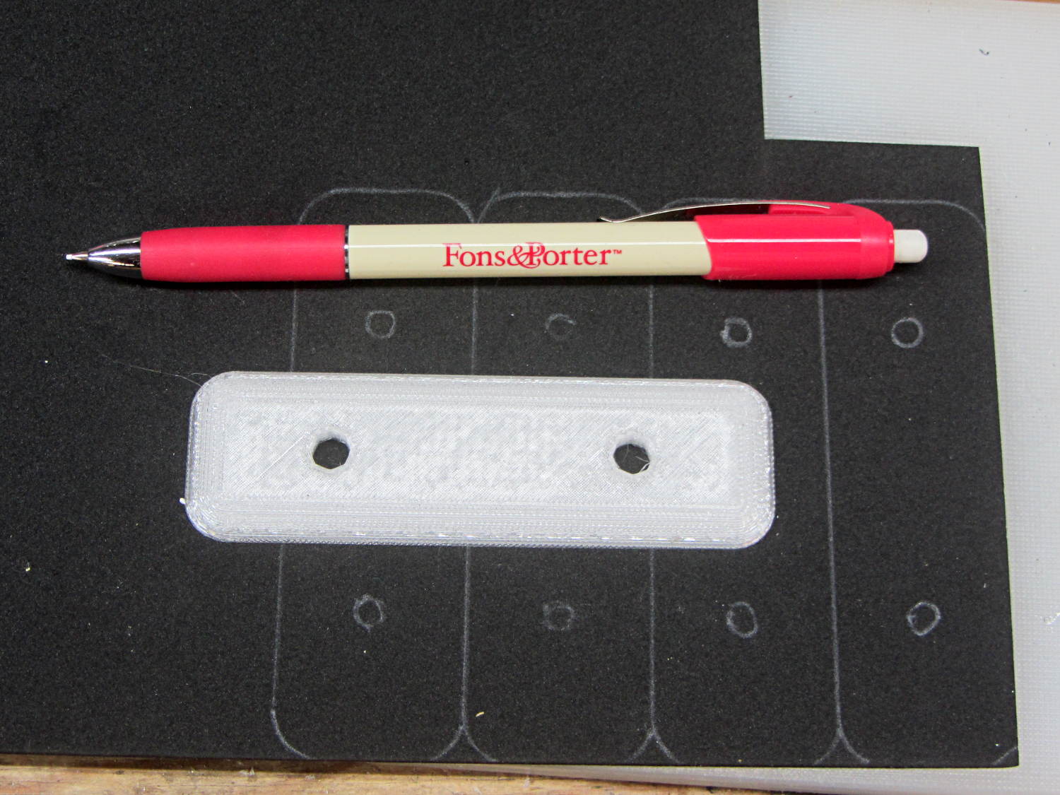
This worked surprisingly well to lay out black foam gaskets for new fairing mounting plates:
Black foam layout with ceramic fabric pen
Mary uses the Fons & Porter Mechanical Pencil to mark quilting patterns on fabric. It has, they say, a “strong ceramic 0.9MM white lead” with “water-soluble dyes” capable of both laying down a durable mark and washing out without leaving a trace. I don’t care about the latter, of course, but it did brush off reasonably well.
The next step involved running an X-Acto knife around the perimeter of the plate and punching the holes.
You can get colored ceramic leads (for small values of color) for use on other backgrounds.
With the information you shared, we were able to successfully model and reconstruct the drive wheel in only a couple of days.
One useful thing we discovered is there’s a lot of room for error – so long as the pin catches and the wheel isn’t slipping on the motor shaft, the mechanism will work. The grooves and the interior radius of the original part aren’t critical.
Because of your heads up about Geneva wheels, I found this excellent website – https://newgottland.com/2012/01/08/make-geneva-wheels-of-any-size/ – which includes a link to a Geneva wheel calculator. With the measurements you sent and a measurement off of the pen carousel, the calculator generated near perfect dimensions for a replacement. There was a little sanding and rounding to fit but it was certainly within tolerance.
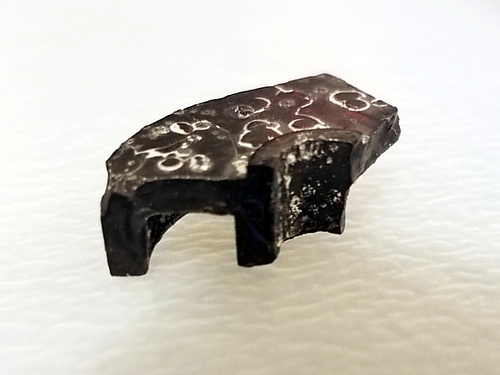
Interestingly, the pieces of the drive wheel that I pulled out of the case revealed a small hidden detail. On the underside, there’s a collar around the motor shaft that gives the cam an extra ~.03″ thickness. Presumably this is to help reduce friction during travel. Our prototype doesn’t take this detail into consideration – we’ve had no issues with friction, and we compensated for the thickness by making the pin a little longer – but it’s meaningful to note.
HP7475A Carousel Drive – cam1
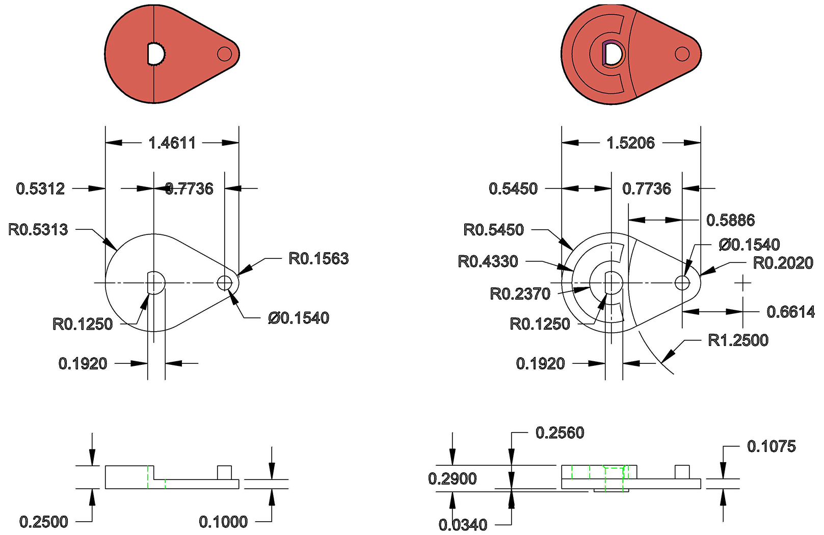
The broken pieces also confirmed the thicknesses and radii of the original part, and so my partner was able to build an accurate technical drawing of the drive wheel for future fabrication.
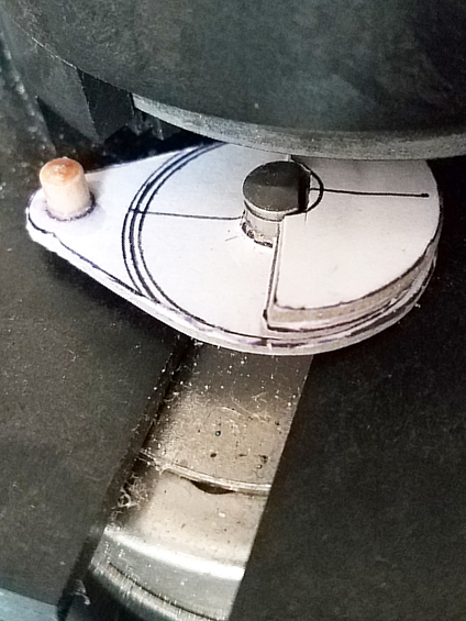
While we intend to make a better replacement, our prototype was built with dense 1/8″ mat board, PVA glue, binder clips, and a short piece of wooden dowel from our bits box. Basically just stuff we had kicking around the studio. It’s held up shockingly well. A little dented around the edges from hitting the carousel, but there’s no slippage. I’m thinking I’ll use it until it falls apart, just to see how long it takes.
HP7475A Carousel Drive – repaired – cam2
Attached, find a technical drawing comparing the original drawing to our prototype (measured in good old fashioned 1980s inches); a photo of the retrieved piece, showing the collar on the reverse side; and a photo of the prototype in place. Feel free to share these – everyone deserves a working plotter!
7475a drive wheel
Once the carousel was working, my roommate – an electrical engineer – hooked me up with a custom serial cable, a Raspberry Pi, and a crash course in Python, so now that I can communicate with the plotter, the possibilities are staggering. I’m thrilled to add this machine to my print studio arsenal!
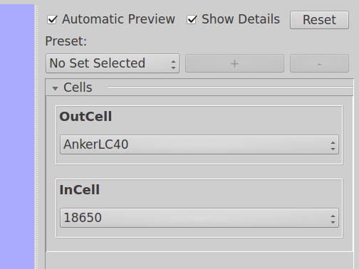
Anker LC40 flashlights can use either one lithium 18650 cell or an adapter holding three AAA cells. I now prefer 18650 cells, but they’re nigh onto 4 mm smaller than the flashlight ID and rattle around something awful.
There’s not much room on an AT26 / TF26 can for a readable label, unless one owns a metal-marking laser, but a simple bar code should let me identify each one:
Quartz Resonators – binary marking
The empty “0” slot down at the bottom will hold the crash-test dummy resonator I’ve been using to get the tester working.
The red-and-blue stripes from plain old fine-point Sharpie pens will rub off under duress, which I hope to avoid. After finishing up, I’m still not sure blue makes a better zero than red; you can make a convincing argument either way:
Binary marked AT26 Quartz Resonators
The bag allegedly contained 25 resonators, although I’m willing to agree the last one escaped into the clutter on or under the Electronics Workbench.
A Circuit Cellar reader asked for a better explanation of the parasitic capacitors inside a quartz crystal can than I provided in my April 2017 Circuit Cellar column. Here’s the schematic, with values for a 32 kHz tuning fork resonator and the original caption:
Figure 1 – The mechanical properties of quartz resonators determine the values of the “motional” electrical components in the bottom branch of its circuit model. These values correspond to a 32.768 kHz quartz tuning fork resonator: the 10.4 kH inductor is not a misprint!
I wrote this about the caps:
The value of C0 in the model’s middle branch corresponds to the capacitance between the electrodes plated onto the quartz. The 3.57954 MHz crystal in the title photo, with two silver electrodes deposited on a flat insulating disk, closely resembles an ordinary capacitor. You can measure a crystal’s C0 using a capacitance meter.
However, each of those electrodes also has a capacitance to the resonator’s metal case. The top branch of the model shows two capacitors in series, with Cpar representing half the total parasitic capacitance measured between both leads and the case. Grounding the case, represented by the conductor between the capacitors, by soldering it to the ground plane of an RF circuit eliminates any signal transfer through those capacitors. They will appear as shunt capacitors between the pins and ground; in critical applications, you must add their capacitance to the external load capacitors.
With the resonator case captured under the clip on the far right and both its leads held by the clip to the upper left, the meter measures Cpar, the lead-to-case parasitic capacitance. The meter will display twice the value of each parasitic capacitor, at least to a good approximation, because they are in parallel. The five resonators averaged 0.45 pF, with each lead having about 0.25 pF of capacitance to the case. Obviously, measuring half a picofarad requires careful zeroing and a stable fixture: a not-quite-tight banana jack nut caused baffling errors during my first few measurements.
With the resonator repositioned as shown in Photo 2, with one lead under each clip, the meter measures C0, the lead-to-lead capacitance. After careful zeroing, the resonators averaged 0.85 pF.
Although the parasitic lead-to-case capacitors are in parallel with C0, their equivalent capacitance is only Cpar/4 = 0.1 pF. That’s close enough to the measurement error for C0, so I ignored it by rounding C0 upward.
He quite correctly pointed out:
With both leads connected together on one side, then that essentially constitutes a single electrical element inside the case. And with the case being a single element, this configuration in the test fixture seems like a single capacitor with one lead being the case and the other lead being the pins, with a vacuum dielectric.
I would think the meter would display the total capacitance rather than twice the value … It makes sense to me to later say Cpar/2 when the leads are not connected together.
Here’s my second pass at the problem:
… the two-capacitor model comes from the common-case condition, where each lead displays a (nominally equal) parasitic capacitance to the case, because the crystal mounting is reasonably symmetric inside the can. It’s easiest to measure the total capacitance with the leads shorted together, because it’s in the low pF range, then divide by two to get the value of each lead-to-case cap.
[…]
For “real” RF circuits with larger (HC-49 -ish) crystals in parallel-resonance mode, you ground the case and subtract the parasitic capacitance at each lead from the external load capacitors. That’s the usual situation for microprocessor clock oscillators: the crystal sits across the clock amplifier pins, with two more-or-less equal caps from the pins to ground. You should subtract the internal parasitic caps from the clock’s specified load caps, but in practice the values are so small and the cap tolerance so large that it mostly doesn’t matter.
[…]
Un-grounding the case puts those two parasitic caps in series, just as with two discrete caps, so the lead-to-lead capacitance is (or should be!) half of each: 1/4 of the both-leads-to-case value.
Re-reading yet again says I glossed over the effect of having C0 in parallel with the Cpar/2 caps, but methinks dragging those complications into the model benefits only the theoreticians among us (or those working very close to the edge of the possible).
To make it worse, I also botched the QEX reference, which should be Jan/Feb 2016, not 2017. Verily, having a column go read-only makes the errors jump right off the page. [sigh]
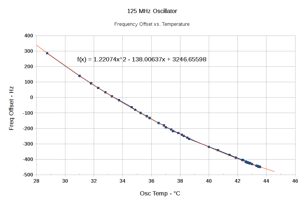
I let the DDS cool down overnight, turned it on, and recorded the frequency offset as a function of temperature as it heated up again:
125 MHz Osc Freq Offset vs Temp – Quadratic – 29 – 43 C
The reduced spacing between the points as the temperature increases shows how fast the oscillator heats up. I zero-beat the 10 MHz output, scribbled the temperature, noted the offset, and iterated as fast as I could. The clump of data over on the right end comes from the previous session with essentially stable temperatures.
I only had to throw out two data points to get such a beautiful fit; the gaps should be obvious.
The fit seems fine from room (well, basement) ambient up to hotter than you’d really like to treat the DDS, so using the quadratic equation should allow on-the-fly temperature compensation. Assuming, of course, the equation matches some version of reality close to the one prevailing in the Basement Laboratory, which remains to be seen.
In truth, it probably doesn’t, because the temperature was changing so rapidly the observations all run a bit behind reality. You’d want a temperature-controlled environment around the PCB to let the oscillator stabilize after each increment, then take the measurements. I am so not going to go there.
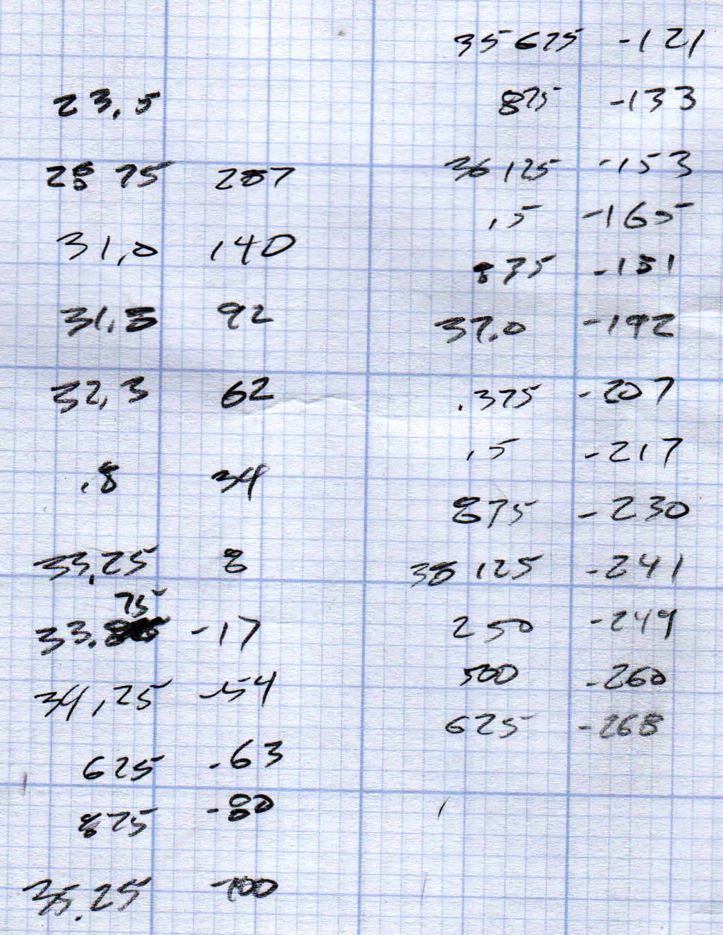
The original data:
125 MHz Osc Freq Offset vs Temp – 29 – 43 C – data
DDS Oscillator Frequency Offset vs. Temperature – complete
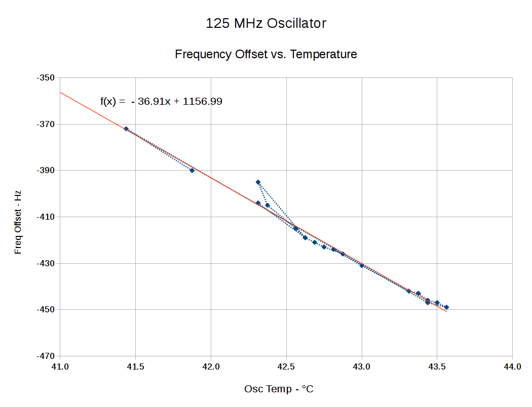
Now, as it turns out, the one lonely little dot off the line happened just after I lit the board up after a tweak, so the oscillator temperature hadn’t stabilized. Tossing it out produces a much nicer fit:
DDS Oscillator Frequency Offset vs. Temperature
Looks like I made it up, doesn’t it?
The first-order coefficient shows the frequency varies by -36 Hz/°C. The actual oscillator frequency decreases with increasing temperature, which means the compensating offset must become more negative to make the oscillator frequency variable match reality. In previous iterations, I’ve gotten this wrong.
For example, at 42.5 °C the oscillator runs at:
125.000000 MHz - 412 Hz = 124.999588 MHz
Dividing that into 232 = 34.35985169 count/Hz, which is the coefficient converting a desired frequency into the DDS delta phase register value. Then, to get 10.000000 MHz at the DDS output, you multiply: 10×106 × 34.35985169 = 343.598517×10⁶
Stuff that into the DDS and away it goes.
Warmed half a degree to 43.0 °C, the oscillator runs at:
125.000000 MHz - 430 Hz = 124.999570 MHz
That’s 18 Hz lower, so the coefficient becomes 34.35985667, and the corresponding delta phase for a 10 MHz output is 343.598567×10⁶.
After insulating the DDS module to reduce the effect of passing breezes, I thought the oscillator temperature would track the ambient temperature fairly closely, because of the more-or-less constant power dissipation inside the foam blanket. Which turned out to be the case:
DDS Oscillator Temperature vs. Ambient
The little dingle-dangle shows startup conditions, where the oscillator warms up at a constant room temperature. The outlier dot sits 0.125 °C to the right of the lowest pair of points, being really conspicuous, which was another hint it didn’t belong with the rest of the contestants.
So, given the ambient temperature, the oscillator temperature will stabilize at 0.97 × ambient + 20.24, which is close enough to a nice, even 20 °C hotter.
The insulation blanket reduces short-term variations due to breezes, which, given the -36 Hz/°C = 0.29 ppm temperature coefficient, makes good sense; you can watch the DDS output frequency blow in the breeze. It does, however, increase the oscillator temperature enough to drop the frequency by 720 Hz, so you probably shouldn’t use the DDS oscillator without compensating for at least its zero-th order offset at whatever temperature you expect.
Of course, that’s over a teeny-tiny temperature range, where nearly anything would be linear.