The Smell of Molten Projects in the Morning

Ed Nisley's Blog: Shop notes, electronics, firmware, machinery, 3D printing, laser cuttery, and curiosities. Contents: 100% human thinking, 0% AI slop.

Category: Software

General-purpose computers doing something specific

  • LinuxCNC: Mesa 5I25 For The Sherline Mill

    LinuxCNC: Mesa 5I25 For The Sherline Mill

    Updating the Sherline’s LinuxCNC from 2.7.ancient to 2.8.1, which I did by the simple expedient of replacing the hard drive with an SSD from the heap and doing a clean installation, provided the opportunity of switching from the parallel port to a Mesa 5I25 FPGA card to put timing-critical step generation under hardware control.

    I has flashed the card with Mesa’s Probotix PBX-RF BIT file, then invoked it with a configuration string turning off everything except the stepgen modules:

    loadrt hm2_pci config="num_encoders=0 num_pwmgens=0 num_stepgens=4"
    

    Which produces a simple pinout on the back panel DB-25 connector:

    hm2_pci: loading Mesa AnyIO HostMot2 driver version 0.7
    hm2_pci: discovered 5i25 at 0000:04:02.0
    hm2/hm2_5i25.0: Low Level init 0.15
    hm2/hm2_5i25.0: 34 I/O Pins used:
    hm2/hm2_5i25.0:     IO Pin 000 (P3-01): IOPort
    hm2/hm2_5i25.0:     IO Pin 001 (P3-14): IOPort
    hm2/hm2_5i25.0:     IO Pin 002 (P3-02): StepGen #0, pin Step (Output)
    hm2/hm2_5i25.0:     IO Pin 003 (P3-15): IOPort
    hm2/hm2_5i25.0:     IO Pin 004 (P3-03): StepGen #0, pin Direction (Output)
    hm2/hm2_5i25.0:     IO Pin 005 (P3-16): IOPort
    hm2/hm2_5i25.0:     IO Pin 006 (P3-04): StepGen #1, pin Step (Output)
    hm2/hm2_5i25.0:     IO Pin 007 (P3-17): IOPort
    hm2/hm2_5i25.0:     IO Pin 008 (P3-05): StepGen #1, pin Direction (Output)
    hm2/hm2_5i25.0:     IO Pin 009 (P3-06): StepGen #2, pin Step (Output)
    hm2/hm2_5i25.0:     IO Pin 010 (P3-07): StepGen #2, pin Direction (Output)
    hm2/hm2_5i25.0:     IO Pin 011 (P3-08): StepGen #3, pin Step (Output)
    hm2/hm2_5i25.0:     IO Pin 012 (P3-09): StepGen #3, pin Direction (Output)
    hm2/hm2_5i25.0:     IO Pin 013 (P3-10): IOPort
    hm2/hm2_5i25.0:     IO Pin 014 (P3-11): IOPort
    hm2/hm2_5i25.0:     IO Pin 015 (P3-12): IOPort
    hm2/hm2_5i25.0:     IO Pin 016 (P3-13): IOPort


    The Sherline CNC driver requires an adapter to swap the Step and Direction signals on the output connector.

    The Sherline controller expects active-low Step signals:

    # invert step output bits
    setp   [HMOT](FPGA0).gpio.002.invert_output     1
    setp   [HMOT](FPGA0).gpio.006.invert_output     1
    setp   [HMOT](FPGA0).gpio.009.invert_output     1
    setp   [HMOT](FPGA0).gpio.011.invert_output     1
    

    The Y and Z drivers needed the same Direction swap as before:

    # invert direction output bits
    setp   [HMOT](FPGA0).gpio.008.invert_output     1
    setp   [HMOT](FPGA0).gpio.010.invert_output     1
    

    Because the 5I25 uses 3.3 V logic with interface drivers to match the “parallel port” 5 V levels, it has different electrical characteristics than the parallel port built into the Dell Optiplex 760. Putting a 100 nF cap across the Probe input reduced, but did not eliminate, what looked like a nice 60 Hz signal on that long wire, so I added a firmware debouncer:

    loadrt debounce cfg=2
    addf debounce.0               servo-thread
    setp debounce.0.delay 3
    
    net probe-raw debounce.0.1.in [HMOT](FPGA0).gpio.003.in_not
    net probe-in debounce.0.1.out
    

    The additional 3 ms delay doesn’t amount to much distance, even were I to probe at the machine’s top 10 mm/s speed.

    Although the seemingly identical Home switch input seemed stable, it got the same treatment:

    net home-raw debounce.0.0.in [HMOT](FPGA0).gpio.013.in_not
    net all-home debounce.0.0.out
    

    The PID loops have a very simple setup, with P = 1000 and FF1 = 1, which seems entirely adequate without any attempt at tuning. The following errors seems to stay under 20 ppm, in the machine’s native inches, while cutting the standard Axis “splash G-Code” file with all the speeds cranked up to 24 in/min = 610 mm/min:

    LinuxCNC - Sherline f-error
    LinuxCNC – Sherline f-error

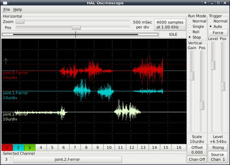
    Claiming a 20 µinch error for a Sherline is certainly aspirational.

    The INI and HAL files as a GitHub Gist:

    # DO NOT RUN PNCCONF EVER AGAIN
    loadrt [KINS]KINEMATICS
    loadrt [EMCMOT]EMCMOT servo_period_nsec=[EMCMOT]SERVO_PERIOD num_joints=[KINS]JOINTS
    loadrt hostmot2
    loadrt hm2_pci config="num_encoders=0 num_pwmgens=0 num_stepgens=4"
    loadrt debounce cfg=2
    addf debounce.0 servo-thread
    setp debounce.0.delay 3
    setp [HMOT](FPGA0).watchdog.timeout_ns 5000000
    loadrt pid names=pid.x,pid.y,pid.z,pid.a
    addf [HMOT](FPGA0).read servo-thread
    addf motion-command-handler servo-thread
    addf motion-controller servo-thread
    addf pid.x.do-pid-calcs servo-thread
    addf pid.y.do-pid-calcs servo-thread
    addf pid.z.do-pid-calcs servo-thread
    addf pid.a.do-pid-calcs servo-thread
    addf [HMOT](FPGA0).write servo-thread
    # external output signals
    #setp [HMOT](FPGA0).gpio.000.out 1
    net estop-out [HMOT](FPGA0).gpio.000.out
    #net all-amps-enabled logic.0.and [HMOT](FPGA0).gpio.007.out
    # Home switch
    net home-raw debounce.0.0.in [HMOT](FPGA0).gpio.013.in_not
    net all-home debounce.0.0.out
    # Probe switch
    net probe-raw debounce.0.1.in [HMOT](FPGA0).gpio.003.in_not
    net probe-in debounce.0.1.out
    #*******************
    # AXIS X JOINT 0
    #*******************
    setp pid.x.Pgain [JOINT_0]P
    setp pid.x.Igain [JOINT_0]I
    setp pid.x.Dgain [JOINT_0]D
    setp pid.x.bias [JOINT_0]BIAS
    setp pid.x.FF0 [JOINT_0]FF0
    setp pid.x.FF1 [JOINT_0]FF1
    setp pid.x.FF2 [JOINT_0]FF2
    setp pid.x.deadband [JOINT_0]DEADBAND
    setp pid.x.maxoutput [JOINT_0]MAX_OUTPUT
    setp pid.x.error-previous-target true
    # This setting is to limit bogus stepgen
    # velocity corrections caused by position
    # feedback sample time jitter.
    setp pid.x.maxerror 0.000500
    net x-index-enable <=> pid.x.index-enable
    net x-amp-enable => pid.x.enable
    net x-pos-cmd => pid.x.command
    net x-pos-fb => pid.x.feedback
    net x-output <= pid.x.output
    # Step Gen signals/setup
    setp [HMOT](FPGA0).stepgen.00.dirsetup [JOINT_0]DIRSETUP
    setp [HMOT](FPGA0).stepgen.00.dirhold [JOINT_0]DIRHOLD
    setp [HMOT](FPGA0).stepgen.00.steplen [JOINT_0]STEPLEN
    setp [HMOT](FPGA0).stepgen.00.stepspace [JOINT_0]STEPSPACE
    setp [HMOT](FPGA0).stepgen.00.position-scale [JOINT_0]STEP_SCALE
    setp [HMOT](FPGA0).stepgen.00.step_type 0
    setp [HMOT](FPGA0).stepgen.00.control-type 1
    setp [HMOT](FPGA0).stepgen.00.maxaccel [JOINT_0]STEPGEN_MAXACCEL
    setp [HMOT](FPGA0).stepgen.00.maxvel [JOINT_0]STEPGEN_MAXVEL
    # invert step output bit
    setp [HMOT](FPGA0).gpio.002.invert_output 1
    # —closedloop stepper signals—
    net x-pos-cmd <= joint.0.motor-pos-cmd
    net x-vel-cmd <= joint.0.vel-cmd
    net x-output <= [HMOT](FPGA0).stepgen.00.velocity-cmd
    net x-pos-fb <= [HMOT](FPGA0).stepgen.00.position-fb
    net x-pos-fb => joint.0.motor-pos-fb
    net x-amp-enable <= joint.0.amp-enable-out
    net x-amp-enable => [HMOT](FPGA0).stepgen.00.enable
    # —setup home / limit switch signals—
    net all-home => joint.0.home-sw-in
    net x-neg-limit => joint.0.neg-lim-sw-in
    net x-pos-limit => joint.0.pos-lim-sw-in
    #*******************
    # AXIS Y JOINT 1
    #*******************
    setp pid.y.Pgain [JOINT_1]P
    setp pid.y.Igain [JOINT_1]I
    setp pid.y.Dgain [JOINT_1]D
    setp pid.y.bias [JOINT_1]BIAS
    setp pid.y.FF0 [JOINT_1]FF0
    setp pid.y.FF1 [JOINT_1]FF1
    setp pid.y.FF2 [JOINT_1]FF2
    setp pid.y.deadband [JOINT_1]DEADBAND
    setp pid.y.maxoutput [JOINT_1]MAX_OUTPUT
    setp pid.y.error-previous-target true
    # This setting is to limit bogus stepgen
    # velocity corrections caused by position
    # feedback sample time jitter.
    setp pid.y.maxerror 0.000500
    net y-index-enable <=> pid.y.index-enable
    net y-amp-enable => pid.y.enable
    net y-pos-cmd => pid.y.command
    net y-pos-fb => pid.y.feedback
    net y-output <= pid.y.output
    # Step Gen signals/setup
    setp [HMOT](FPGA0).stepgen.01.dirsetup [JOINT_1]DIRSETUP
    setp [HMOT](FPGA0).stepgen.01.dirhold [JOINT_1]DIRHOLD
    setp [HMOT](FPGA0).stepgen.01.steplen [JOINT_1]STEPLEN
    setp [HMOT](FPGA0).stepgen.01.stepspace [JOINT_1]STEPSPACE
    setp [HMOT](FPGA0).stepgen.01.position-scale [JOINT_1]STEP_SCALE
    setp [HMOT](FPGA0).stepgen.01.step_type 0
    setp [HMOT](FPGA0).stepgen.01.control-type 1
    setp [HMOT](FPGA0).stepgen.01.maxaccel [JOINT_1]STEPGEN_MAXACCEL
    setp [HMOT](FPGA0).stepgen.01.maxvel [JOINT_1]STEPGEN_MAXVEL
    # invert step output bit
    setp [HMOT](FPGA0).gpio.006.invert_output 1
    # invert direction output bit
    setp [HMOT](FPGA0).gpio.008.invert_output 1
    # —closedloop stepper signals—
    net y-pos-cmd <= joint.1.motor-pos-cmd
    net y-vel-cmd <= joint.1.vel-cmd
    net y-output <= [HMOT](FPGA0).stepgen.01.velocity-cmd
    net y-pos-fb <= [HMOT](FPGA0).stepgen.01.position-fb
    net y-pos-fb => joint.1.motor-pos-fb
    net y-amp-enable <= joint.1.amp-enable-out
    net y-amp-enable => [HMOT](FPGA0).stepgen.01.enable
    # —setup home / limit switch signals—
    net all-home => joint.1.home-sw-in
    net y-neg-limit => joint.1.neg-lim-sw-in
    net y-pos-limit => joint.1.pos-lim-sw-in
    #*******************
    # AXIS Z JOINT 2
    #*******************
    setp pid.z.Pgain [JOINT_2]P
    setp pid.z.Igain [JOINT_2]I
    setp pid.z.Dgain [JOINT_2]D
    setp pid.z.bias [JOINT_2]BIAS
    setp pid.z.FF0 [JOINT_2]FF0
    setp pid.z.FF1 [JOINT_2]FF1
    setp pid.z.FF2 [JOINT_2]FF2
    setp pid.z.deadband [JOINT_2]DEADBAND
    setp pid.z.maxoutput [JOINT_2]MAX_OUTPUT
    setp pid.z.error-previous-target true
    # This setting is to limit bogus stepgen
    # velocity corrections caused by position
    # feedback sample time jitter.
    setp pid.z.maxerror 0.000500
    net z-index-enable <=> pid.z.index-enable
    net z-amp-enable => pid.z.enable
    net z-pos-cmd => pid.z.command
    net z-pos-fb => pid.z.feedback
    net z-output <= pid.z.output
    # Step Gen signals/setup
    setp [HMOT](FPGA0).stepgen.02.dirsetup [JOINT_2]DIRSETUP
    setp [HMOT](FPGA0).stepgen.02.dirhold [JOINT_2]DIRHOLD
    setp [HMOT](FPGA0).stepgen.02.steplen [JOINT_2]STEPLEN
    setp [HMOT](FPGA0).stepgen.02.stepspace [JOINT_2]STEPSPACE
    setp [HMOT](FPGA0).stepgen.02.position-scale [JOINT_2]STEP_SCALE
    setp [HMOT](FPGA0).stepgen.02.step_type 0
    setp [HMOT](FPGA0).stepgen.02.control-type 1
    setp [HMOT](FPGA0).stepgen.02.maxaccel [JOINT_2]STEPGEN_MAXACCEL
    setp [HMOT](FPGA0).stepgen.02.maxvel [JOINT_2]STEPGEN_MAXVEL
    # invert step output bit
    setp [HMOT](FPGA0).gpio.009.invert_output 1
    # invert direction output bit
    setp [HMOT](FPGA0).gpio.010.invert_output 1
    # —closedloop stepper signals—
    net z-pos-cmd <= joint.2.motor-pos-cmd
    net z-vel-cmd <= joint.2.vel-cmd
    net z-output <= [HMOT](FPGA0).stepgen.02.velocity-cmd
    net z-pos-fb <= [HMOT](FPGA0).stepgen.02.position-fb
    net z-pos-fb => joint.2.motor-pos-fb
    net z-amp-enable <= joint.2.amp-enable-out
    net z-amp-enable => [HMOT](FPGA0).stepgen.02.enable
    # —setup home / limit switch signals—
    net all-home => joint.2.home-sw-in
    net z-neg-limit => joint.2.neg-lim-sw-in
    net z-pos-limit => joint.2.pos-lim-sw-in
    #*******************
    # AXIS A JOINT 3
    #*******************
    setp pid.a.Pgain [JOINT_3]P
    setp pid.a.Igain [JOINT_3]I
    setp pid.a.Dgain [JOINT_3]D
    setp pid.a.bias [JOINT_3]BIAS
    setp pid.a.FF0 [JOINT_3]FF0
    setp pid.a.FF1 [JOINT_3]FF1
    setp pid.a.FF2 [JOINT_3]FF2
    setp pid.a.deadband [JOINT_3]DEADBAND
    setp pid.a.maxoutput [JOINT_3]MAX_OUTPUT
    setp pid.a.error-previous-target true
    # This setting is to limit bogus stepgen
    # velocity corrections caused by position
    # feedback sample time jitter.
    setp pid.a.maxerror 0.000500
    net a-index-enable <=> pid.a.index-enable
    net a-amp-enable => pid.a.enable
    net a-pos-cmd => pid.a.command
    net a-pos-fb => pid.a.feedback
    net a-output <= pid.a.output
    # Step Gen signals/setup
    setp [HMOT](FPGA0).stepgen.03.dirsetup [JOINT_3]DIRSETUP
    setp [HMOT](FPGA0).stepgen.03.dirhold [JOINT_3]DIRHOLD
    setp [HMOT](FPGA0).stepgen.03.steplen [JOINT_3]STEPLEN
    setp [HMOT](FPGA0).stepgen.03.stepspace [JOINT_3]STEPSPACE
    setp [HMOT](FPGA0).stepgen.03.position-scale [JOINT_3]STEP_SCALE
    setp [HMOT](FPGA0).stepgen.03.step_type 0
    setp [HMOT](FPGA0).stepgen.03.control-type 1
    setp [HMOT](FPGA0).stepgen.03.maxaccel [JOINT_3]STEPGEN_MAXACCEL
    setp [HMOT](FPGA0).stepgen.03.maxvel [JOINT_3]STEPGEN_MAXVEL
    # invert step output bit
    setp [HMOT](FPGA0).gpio.011.invert_output 1
    # —closedloop stepper signals—
    net a-pos-cmd <= joint.3.motor-pos-cmd
    net a-vel-cmd <= joint.3.vel-cmd
    net a-output <= [HMOT](FPGA0).stepgen.03.velocity-cmd
    net a-pos-fb <= [HMOT](FPGA0).stepgen.03.position-fb
    net a-pos-fb => joint.3.motor-pos-fb
    net a-amp-enable <= joint.3.amp-enable-out
    net a-amp-enable => [HMOT](FPGA0).stepgen.03.enable
    # —setup home / limit switch signals—
    net all-home => joint.3.home-sw-in
    net a-neg-limit => joint.3.neg-lim-sw-in
    net a-pos-limit => joint.3.pos-lim-sw-in
    #******************************
    # connect miscellaneous signals
    #******************************
    # —HALUI signals—
    net axis-select-x halui.axis.x.select
    net x-is-homed halui.joint.0.is-homed
    net axis-select-y halui.axis.y.select
    net y-is-homed halui.joint.1.is-homed
    net axis-select-z halui.axis.z.select
    net z-is-homed halui.joint.2.is-homed
    net axis-select-a halui.axis.a.select
    net a-is-homed halui.joint.3.is-homed
    net jog-selected-pos halui.axis.selected.plus
    net jog-selected-neg halui.axis.selected.minus
    net spindle-manual-cw halui.spindle.0.forward
    net spindle-manual-ccw halui.spindle.0.reverse
    net spindle-manual-stop halui.spindle.0.stop
    net MDI-mode halui.mode.is-mdi
    # —coolant signals—
    net coolant-mist <= iocontrol.0.coolant-mist
    net coolant-flood <= iocontrol.0.coolant-flood
    # —probe signal—
    net probe-in => motion.probe-input
    # —motion control signals—
    net in-position <= motion.in-position
    net machine-is-enabled <= motion.motion-enabled
    # —digital in / out signals—
    # —estop signals—
    net estop-out <= iocontrol.0.user-enable-out
    net estop-out => iocontrol.0.emc-enable-in
    # —manual tool change signals—
    loadusr -W hal_manualtoolchange
    net tool-change-request iocontrol.0.tool-change => hal_manualtoolchange.change
    net tool-change-confirmed iocontrol.0.tool-changed <= hal_manualtoolchange.changed
    net tool-number iocontrol.0.tool-prep-number => hal_manualtoolchange.number
    net tool-prepare-loopback iocontrol.0.tool-prepare => iocontrol.0.tool-prepared
    view raw razor-5i25.hal hosted with ❤ by GitHub
    # DO NOT RUN PNCCONF EVER AGAIN
    [EMC]
    MACHINE = Razor-5i25
    DEBUG = 0
    VERSION = 1.1
    [DISPLAY]
    DISPLAY = axis
    POSITION_OFFSET = RELATIVE
    POSITION_FEEDBACK = ACTUAL
    MAX_FEED_OVERRIDE = 2.000000
    MAX_SPINDLE_OVERRIDE = 1.000000
    MIN_SPINDLE_OVERRIDE = 0.500000
    INTRO_GRAPHIC = /home/ed/linuxcnc/configs/razor-5i25/Sherline.gif
    INTRO_TIME = 3
    PROGRAM_PREFIX = /mnt/bulkdata/
    INCREMENTS = 50mm 10mm 1mm 0.1mm 90 45 10 5 1
    GRIDS = 100mm 50mm 25mm 10mm 5mm
    POSITION_FEEDBACK = ACTUAL
    DEFAULT_LINEAR_VELOCITY = 0.200000
    MAX_LINEAR_VELOCITY = 0.400000
    MIN_LINEAR_VELOCITY = 0.016670
    DEFAULT_ANGULAR_VELOCITY = 12.000000
    MAX_ANGULAR_VELOCITY = 180.000000
    MIN_ANGULAR_VELOCITY = 1.666667
    EDITOR = gedit
    GEOMETRY = axyz
    [FILTER]
    PROGRAM_EXTENSION = .png,.gif,.jpg Greyscale Depth Image
    PROGRAM_EXTENSION = .py Python Script
    png = image-to-gcode
    gif = image-to-gcode
    jpg = image-to-gcode
    py = python
    [TASK]
    TASK = milltask
    CYCLE_TIME = 0.010
    [RS274NGC]
    PARAMETER_FILE = linuxcnc.var
    RS274NGC_STARTUP_CODE = G21 G40 G49 G54 G80 G90 G92.1 G94 G97 G98
    [EMCMOT]
    EMCMOT = motmod
    COMM_TIMEOUT = 1.0
    SERVO_PERIOD = 1000000
    [HMOT]
    FPGA0 = hm2_5i25.0
    [HAL]
    TWOPASS = on
    HALUI = halui
    HALFILE = razor-5i25.hal
    #HALFILE = joggy.hal
    HALFILE = custom.hal
    POSTGUI_HALFILE = postgui_call_list.hal
    SHUTDOWN = shutdown.hal
    #HALFILE = LIB:halcheck.tcl
    [HALUI]
    [KINS]
    JOINTS = 4
    KINEMATICS = trivkins coordinates=XYZA
    [TRAJ]
    COORDINATES = XYZA
    LINEAR_UNITS = inch
    ANGULAR_UNITS = degree
    DEFAULT_LINEAR_VELOCITY = 0.10
    MAX_LINEAR_VELOCITY = 0.4
    MAX_ANGULAR_VELOCITY = 45
    DEFAULT_ANGULAR_VELOCITY = 25.00
    NO_FORCE_HOMING = 1
    POSITION_FILE = lastposition.txt
    [EMCIO]
    EMCIO = io
    CYCLE_TIME = 0.100
    TOOL_TABLE = tool.tbl
    #******************************************
    [AXIS_X]
    MIN_LIMIT = -1.0
    MAX_LIMIT = 9.5
    MAX_VELOCITY = 0.4
    MAX_ACCELERATION = 5.0
    [JOINT_0]
    TYPE = LINEAR
    FERROR = 0.01
    MIN_FERROR = 0.001
    MAX_VELOCITY = 0.4
    MAX_ACCELERATION = 5.0
    BACKLASH = 0.003
    # The values below should be 25% larger than MAX_VELOCITY and MAX_ACCELERATION
    # If using BACKLASH compensation STEPGEN_MAXACCEL should be 100% larger.
    STEPGEN_MAXVEL = 0.6
    STEPGEN_MAXACCEL = 20
    P = 1000.0
    I = 0.0
    D = 0.0
    FF0 = 0.0
    FF1 = 1.0
    FF2 = 0.0
    BIAS = 0.0
    DEADBAND = 0.0
    MAX_OUTPUT = 0.0
    # these are in nanoseconds
    DIRSETUP = 25000
    DIRHOLD = 25000
    STEPLEN = 25000
    STEPSPACE = 25000
    STEP_SCALE = 16000
    MIN_LIMIT = -1.0
    MAX_LIMIT = 9.5
    HOME = 5.25
    HOME_OFFSET = 9.1
    HOME_SEARCH_VEL = 0.3
    HOME_LATCH_VEL = 0.03
    HOME_FINAL_VEL = 0.4
    HOME_USE_INDEX = NO
    HOME_IS_SHARED = 1
    HOME_SEQUENCE = 1
    #******************************************
    #******************************************
    [AXIS_Y]
    MIN_LIMIT = 0.00
    MAX_LIMIT = 5.10
    MAX_VELOCITY = 0.4
    MAX_ACCELERATION = 5.0
    [JOINT_1]
    TYPE = LINEAR
    FERROR = 0.01
    MIN_FERROR = 0.001
    MAX_VELOCITY = 0.4
    MAX_ACCELERATION = 5.0
    BACKLASH = 0.003
    # The values below should be 25% larger than MAX_VELOCITY and MAX_ACCELERATION
    # If using BACKLASH compensation STEPGEN_MAXACCEL should be 100% larger.
    STEPGEN_MAXVEL = 0.6
    STEPGEN_MAXACCEL = 10.0
    P = 1000.0
    I = 0.0
    D = 0.0
    FF0 = 0.0
    FF1 = 1.0
    FF2 = 0.0
    BIAS = 0.0
    DEADBAND = 0.0
    MAX_OUTPUT = 0.0
    # these are in nanoseconds
    DIRSETUP = 25000
    DIRHOLD = 25000
    STEPLEN = 25000
    STEPSPACE = 25000
    STEP_SCALE = 16000
    MIN_LIMIT = 0.0
    MAX_LIMIT = 5.1
    HOME = 4.5
    HOME_OFFSET = 5.1
    HOME_SEARCH_VEL = 0.3
    HOME_LATCH_VEL = 0.03
    HOME_FINAL_VEL = 0.4
    HOME_USE_INDEX = NO
    HOME_IS_SHARED = 1
    HOME_SEQUENCE = 2
    #******************************************
    #******************************************
    [AXIS_Z]
    MIN_LIMIT = 0.0
    MAX_LIMIT = 6.680
    MAX_VELOCITY = 0.333
    MAX_ACCELERATION = 3.0
    [JOINT_2]
    TYPE = LINEAR
    FERROR = 0.01
    MIN_FERROR = 0.001
    MAX_VELOCITY = 0.333
    MAX_ACCELERATION = 3.0
    BACKLASH = 0.005
    # The values below should be 25% larger than MAX_VELOCITY and MAX_ACCELERATION
    # If using BACKLASH compensation STEPGEN_MAXACCEL should be 100% larger.
    STEPGEN_MAXVEL = 0.6
    STEPGEN_MAXACCEL = 6
    P = 1000.0
    I = 0.0
    D = 0.0
    FF0 = 0.0
    FF1 = 1.0
    FF2 = 0.0
    BIAS = 0.0
    DEADBAND = 0.0
    MAX_OUTPUT = 0.0
    # these are in nanoseconds
    DIRSETUP = 25000
    DIRHOLD = 25000
    STEPLEN = 25000
    STEPSPACE = 25000
    STEP_SCALE = 16000
    MIN_LIMIT = 0.0
    MAX_LIMIT = 6.68
    HOME = 6.5
    HOME_OFFSET = 6.68
    HOME_SEARCH_VEL = 0.15
    HOME_LATCH_VEL = 0.015
    HOME_FINAL_VEL = 0.33
    HOME_USE_INDEX = NO
    HOME_IS_SHARED = 1
    HOME_SEQUENCE = 0
    #******************************************
    #******************************************
    [AXIS_A]
    MIN_LIMIT = -9999999
    MAX_LIMIT = 9999999
    MAX_VELOCITY = 45.0
    MAX_ACCELERATION = 250.0
    [JOINT_3]
    TYPE = ANGULAR
    FERROR = 0.1
    MIN_FERROR = 0.01
    MAX_VELOCITY = 45.0
    MAX_ACCELERATION = 250.0
    # The values below should be 25% larger than MAX_VELOCITY and MAX_ACCELERATION
    # If using BACKLASH compensation STEPGEN_MAXACCEL should be 100% larger.
    STEPGEN_MAXVEL = 50
    STEPGEN_MAXACCEL = 300
    P = 1000.0
    I = 0.0
    D = 0.0
    FF0 = 0.0
    FF1 = 1.0
    FF2 = 0.0
    BIAS = 0.0
    DEADBAND = 0.0
    MAX_OUTPUT = 0.0
    # these are in nanoseconds
    DIRSETUP = 25000
    DIRHOLD = 25000
    STEPLEN = 25000
    STEPSPACE = 25000
    STEP_SCALE = 160
    MIN_LIMIT = -9999999
    MAX_LIMIT = 9999999
    HOME = 0.0
    HOME_OFFSET = 0
    HOME_SEARCH_VEL = 0
    HOME_LATCH_VEL = 0
    HOME_FINAL_VEL = 0
    HOME_USE_INDEX = NO
    HOME_SEQUENCE = 3
    #******************************************
    view raw razor-5i25.ini hosted with ❤ by GitHub

    Adapting the HAL code driving my Joggy Thing to its new home didn’t go quite as smoothly, about which, more later.

  • Tek Circuit Computer: Sawed Hairline Fixture

    Tek Circuit Computer: Sawed Hairline Fixture

    This is a fixture to hold a cursor for an Homage Tektronix Circuit Computer while a tiny circular saw blade cuts a narrow flat-bottomed trench:

    Tek CC - sawed cursor - Sherline setup
    Tek CC – sawed cursor – Sherline setup

    Each of the 123 blocks is held to the Sherline tooling plate with a 10-32 SHCS in a little aluminum pin, with another threaded pin for the screw holding the fixture on the side. The minimal top clearance provided some of the motivation behind making those pins in the first place; there’s no room for the usual threaded stud sticking out of the block with a handful of washers under the nut.

    The fixture has locating slots (scribbled with black Sharpie) to touch off the spindle axis and the saw blade at the XZ origin at the pivot hole center. Touching off the saw blade on the cursor surface sets Y=0, although only a few teeth will go ting, so the saw must be spinning.

    I cut the first slot under manual control to a depth of 0.3 mm on a scrap cursor with a grotty engraved hairline:

    Tek CC - first sawed cursor - detail
    Tek CC – first sawed cursor – detail

    It looks better than I expected with some red lacquer crayon scribbled into it:

    Tek CC - first sawed cursor - vs scribed
    Tek CC – first sawed cursor – vs scribed

    A few variations of speed and depth seem inconclusive, although they look more consistent and much smoother than the diamond-drag engraved line with red fill:

    Tek CC - sawed cursor test - magnified
    Tek CC – sawed cursor test – magnified

    The saw produces a ramp at the entry and exit which I don’t like at all, but the cut is, overall, an improvement on the diamond point.

    The OpenSCAD source code as a GitHub Gist:

    // Sawing fixtures for Tek Circuit Computer cursor hairline
    // Ed Nisley KE4ZNU Jan 2021
    // Rotated 90° and screwed to 123 blocks for sawing
    Layout = "Show"; // [Show, Build, Cursor]
    Gap = 4.0;
    /* [Hidden] */
    ThreadThick = 0.25;
    ThreadWidth = 0.40;
    HoleWindage = 0.2;
    Protrusion = 0.1; // make holes end cleanly
    inch = 25.4;
    function IntegerMultiple(Size,Unit) = Unit * ceil(Size / Unit);
    module PolyCyl(Dia,Height,ForceSides=0) { // based on nophead's polyholes
    Sides = (ForceSides != 0) ? ForceSides : (ceil(Dia) + 2);
    FixDia = Dia / cos(180/Sides);
    cylinder(d=(FixDia + HoleWindage),h=Height,$fn=Sides);
    }
    //———————-
    // Dimensions
    CursorHubOD = 1.0*inch; // must match SVG hub OD
    CursorThick = 0.71; // including protective layers
    HairlineMin = 48.4188; // extent of hairline
    HairlineMax = 97.4250;
    HairlineDepth = 0.20;
    PocketDepth = 0.75*CursorThick; // half above surface for taping
    PocketClear = 0.25; // E-Z insertion clearance
    TableOC = [1.16*inch,1.16*inch]; // Sherline tooling plate grid
    BlockOC = [(9/16)*inch,(9/16)*inch]; // 123 block hole grid
    BlockOffset = [(3/8)*inch,(3/8)*inch]; // .. block edge to hole center
    ScrewClear = 5.0; // … screw clearance
    CursorOffset = [2*BlockOC.x,0,0]; // hub center relative to leftmost screw
    FixtureGrid = [5*TableOC.x,0,0]; // size in Table grid units
    Screws = [ // relative to leftmost screw
    [0,0,0], // on table grid
    CursorOffset, // on block grid
    [FixtureGrid.x,0,0] // on table grid
    ];
    echo(str("Screw centers: ",Screws));
    CornerRad = 10.0; // corner radius
    Fixture = [2*CornerRad + FixtureGrid.x,2*CornerRad + CursorHubOD,5.0];
    echo(str("Fixture plate: ",Fixture));
    //———————-
    // Import SVG of cursor outline
    // Requires our CursorHubOD to match actual cut outline
    // Hub center at origin
    module CursorSVG(t=CursorThick,ofs=0.0) {
    hr = CursorHubOD/2;
    translate([-hr,-hr,0])
    linear_extrude(height=t,convexity=3)
    offset(r=ofs)
    import(
    file="/mnt/bulkdata/Project Files/Tektronix Circuit Computer/Firmware/TekCC-Cursor-Mark.svg",
    center=false);
    }
    //———————-
    // Show-n-Tell cursor
    module Cursor() {
    difference() {
    CursorSVG(CursorThick,0.0);
    translate([0,0,-Protrusion])
    rotate(180/6)
    PolyCyl(ScrewClear,CursorThick + 2*Protrusion,6);
    }
    }
    //———————-
    // Sawing fixture for cursor hairline
    // Plate center at origin
    module Fixture() {
    difference() {
    hull() // basic plate shape
    for (i=[-1,1], j=[-1,1])
    translate([i*(Fixture.x/2 – CornerRad),j*(Fixture.y/2 – CornerRad),0])
    cylinder(r=CornerRad,h=Fixture.z,$fn=24);
    translate([0,0,Fixture.z – ThreadThick/2 + Protrusion/2]) // will be Z=0 index
    cube([2*Fixture.x,ThreadWidth,ThreadThick + Protrusion],center=true);
    translate(-FixtureGrid/2) {
    translate(CursorOffset + [0,0,Fixture.z – 2*PocketDepth])
    difference() {
    CursorSVG(2*PocketDepth + Protrusion,PocketClear);
    CursorSVG(PocketDepth + Protrusion,-PocketClear);
    }
    translate([CursorOffset.x,0,Fixture.z – ThreadThick/2 + Protrusion/2]) // will be front X=0 index
    cube([ThreadWidth,2*Fixture.y,ThreadThick + Protrusion],center=true);
    translate([CursorOffset.x,Fixture.y/2 – ThreadThick/2 + Protrusion/2,0]) // will be top X=0 index
    cube([ThreadWidth,ThreadThick + Protrusion,2*Fixture.z],center=true);
    translate([CursorOffset.x + HairlineMin,0,Fixture.z – ThreadThick/2 + Protrusion/2]) // hairline min
    cube([ThreadWidth,2*Fixture.y,ThreadThick + Protrusion],center=true);
    translate([CursorOffset.x + HairlineMax,0,Fixture.z – ThreadThick/2 + Protrusion/2]) // hairline min
    cube([ThreadWidth,2*Fixture.y,ThreadThick + Protrusion],center=true);
    /*
    # translate(CursorOffset + [0,0,Fixture.z – 2*ThreadThick]) { // alignment pips
    for (x=[-20.0,130.0], y=[-30.0,0.0,30.0])
    translate([x,y,0])
    cylinder(d=4*ThreadWidth,h=1,$fn=6);
    # for (x=[-30.0,130.0,150.0])
    translate([x,0,0])
    cylinder(d=4*ThreadWidth,h=1,$fn=6);
    */
    for (pt=Screws)
    translate(pt + [0,0,-Protrusion])
    rotate(180/6)
    PolyCyl(ScrewClear,Fixture.z + 2*Protrusion,6);
    }
    }
    }
    //———————-
    // Build it
    if (Layout == "Cursor") {
    Cursor();
    }
    if (Layout == "Show") {
    rotate([0*90,0,0]) {
    Fixture();
    color("Green",0.3)
    translate(-FixtureGrid/2 + CursorOffset + [0,0,Fixture.z + Gap])
    Cursor();
    }
    }
    if (Layout == "Build"){
    // rotate(90)
    Fixture();
    }

  • Torchiere Lamp Shade 2

    Torchiere Lamp Shade 2

    Three and a half years later, the shade on the living room’s other torchiere lamp crumbled at a touch:

    Torchiere Lamp Shade 2 - crumbled
    Torchiere Lamp Shade 2 – crumbled

    Because I live in the future and had solved this problem in the past, eight hours of print time produced a second shade:

    Torchiere Lamp Shade 2 - on platform
    Torchiere Lamp Shade 2 – on platform

    I sliced the same STL file with PrusaSlicer to get G-Code incorporating whatever configuration changes I’ve made to the M2 over the years and include any slicing algorithm improvements; the OpenSCAD code remains unchanged.

    The as-printed shade had pretty much the same crystalline aspect as the first one:

    Torchiere Lamp Shade 2 - no epoxy
    Torchiere Lamp Shade 2 – no epoxy

    Smoothing a layer of white-tinted epoxy over the interior while spinning it slowly in the mini-lathe calmed it down enough for our simple needs, although the picture I tried to take didn’t show much difference.

    That was easy …

  • Photo Backdrop Clamp Pad Embiggening

    Photo Backdrop Clamp Pad Embiggening

    We got a photo backdrop stand to hold Mary’s show-n-tell quilts during her quilting club meetings, but the clamps intended to hold the backdrop from the top bar don’t work quite the way one might expect. These photos snagged from the listing shows their intended use:

    Emart Photo Backdrop - clamp examples
    Emart Photo Backdrop – clamp examples

    The clamp closes on the top bar with the jaws about 15 mm apart, so you must wrap the backdrop around the bar, thereby concealing the top few inches of whatever you intended to show. This doesn’t matter for a preprinted generic backdrop or a green screen, but quilt borders have interesting detail.

    The clamps need thicker jaws, which I promptly conjured from the vasty digital deep:

    Spring Clamp Pads - PS preview
    Spring Clamp Pads – PS preview

    The original jaws fit neatly into those recesses, atop a snippet of carpet tape to prevent them from wandering off:

    Spring Clamp pads - detail
    Spring Clamp pads – detail

    They’re thick enough to meet in the middle and make the clamp’s serrated round-ish opening fit around the bar:

    Spring Clamp pads - compared
    Spring Clamp pads – compared

    With a quilt in place, the clamps slide freely along the bar:

    Spring Clamp pads - fit test
    Spring Clamp pads – fit test

    That’s a recreation based on actual events, mostly because erecting the stand wasn’t going to happen for one photo.

    To level set your expectations, the “Convenient Carry Bag” is more of a wrap than a bag, without enough fabric to completely surround its contents:

    Emart photo backdrop bag
    Emart photo backdrop bag

    I put all the clamps / hooks / doodads in a quart Ziploc baggie, which seemed like a better idea than letting them rattle around loose inside the wrap. The flimsy pair (!) of hook-n-loop straps don’t reach across the gap and, even extended with a few inches of double-sided Velcro, lack enough mojo to hold it closed against all the contents.

    It’ll suffice for our simple needs, but …

    The OpenSCAD source code as a GitHub Gist:

    // Clamp pads for Emart photo backdrop clamps
    // Ed Nisley KE4ZNU Jan 2021
    /* [Hidden] */
    ThreadThick = 0.25;
    ThreadWidth = 0.40;
    HoleWindage = 0.2;
    Protrusion = 0.1; // make holes end cleanly
    inch = 25.4;
    function IntegerMultiple(Size,Unit) = Unit * ceil(Size / Unit);
    module PolyCyl(Dia,Height,ForceSides=0) { // based on nophead's polyholes
    Sides = (ForceSides != 0) ? ForceSides : (ceil(Dia) + 2);
    FixDia = Dia / cos(180/Sides);
    cylinder(d=(FixDia + HoleWindage),h=Height,$fn=Sides);
    }
    //———————-
    // Dimensions
    OEMpad = [24.0,16.0,3.0]; // original pad
    Pad = [35.0,25.0,8.0 + OEMpad.z]; // pad extension
    PadOffset = [0,-3.0,0];
    CornerRad = 3.0; // corner rounding
    Gap = 3.0;
    //———————-
    // Shape the pad
    module BigPad() {
    difference() {
    hull()
    for (i=[-1,1],j=[-1,1],k=[-1,1])
    translate([i*(Pad.x/2 – CornerRad),j*(Pad.y/2 – CornerRad),k*(Pad.z/2 – CornerRad) + Pad.z/2])
    sphere(r=CornerRad,$fn=6);
    translate(PadOffset + [0,0,Pad.z – (OEMpad.z + Protrusion)/2])
    cube(OEMpad + [HoleWindage,HoleWindage,Protrusion],center=true);
    }
    }
    //———————-
    // Build a pair
    translate([0,(Pad.y + Gap)/2,0])
    BigPad();
    translate([0,-(Pad.y + Gap)/2,0])
    rotate(180)
    BigPad();

  • Tek Circuit Computer: Cursor Milling Toolpath

    Tek Circuit Computer: Cursor Milling Toolpath

    Unlike the adhesive fixture, this setup requires a pause while milling the cursor outline to reclamp it from the front:

    Tek CC Cursor Fixture - outline rear clamp
    Tek CC Cursor Fixture – outline rear clamp

    The trick is applying the front clamp before releasing the rear clamp:

    Tek CC Cursor Fixture - outline both clamp
    Tek CC Cursor Fixture – outline both clamp

    Then continue the mission:

    Tek CC Cursor Fixture - outline front clamp
    Tek CC Cursor Fixture – outline front clamp

    Because the tool path includes cutter compensation, GCMC adds entry and exit arcs to ensure a smooth transition:

    Tek CC Cursor - Milling path
    Tek CC Cursor – Milling path

    The pix show a single cursor in the fixture while verifying the setup worked the way it should. Obviously, milling a stack of cursors eliminates a whole bunch of fiddling.

    The tweaked MillCursor function from the mostly otherwise unchanged GCMC code:

        comment("Clamp on rear half of cursor!");
    
        local cp = {p0};                                             // enter at hub tangent point
        cp += varc_ccw([0mm,-2*p0.y,-],-hr,0,0.2mm,5deg) + p0;       // arc to tangent at hub bottom
    
        cp += {[p1.x,-p1.y,-]};                                      // lower tip entry point
        cp += varc_ccw([p2.x-p1.x,-(p2.y-p1.y),-],CursorTipRadius,0,0.2mm,5deg) + [p1.x,-p1.y,-];  // arc to tip exit at p2
    
        cp += varc_ccw([p1.x-p2.x,p1.y-p2.y,-],CursorTipRadius,0,0.2mm,5deg) + p2;  // arc to tip exit at p1
    
        goto([-,-,CursorSafeZ]);
        goto([0,0,-]);
        feedrate(MillSpeed);
        tracepath_comp(cp,CutterOD/2,TPC_OLDZ + TPC_RIGHT + TPC_ARCIN + TPC_ARCOUT);
    
        comment("Clamp on front half of cursor!");
        pause();                                      // wait for reclamping
    
        p1.z = MillZ;                                //  ... set milling depth
        cp = {p1};
        cp += {p0};
                                                     // exit at hub tangent
        tracepath_comp(cp,CutterOD/2,TPC_OLDZ + TPC_RIGHT + TPC_ARCIN + TPC_ARCOUT);
    
    <<< snippage >>>
    
      goto([-,-,CursorSafeZ]);
      goto([0,0,-]);
    

    Next, scribing a nice hairline with the new fixture.

  • Tek Circuit Computer: 3D Printed Cursor Milling Fixture

    Tek Circuit Computer: 3D Printed Cursor Milling Fixture

    The original Tektronix Circuit Computer cursor was probably die-cut from a larger sheet carrying pre-printed hairlines:

    Tek CC - genuine - detail
    Tek CC – genuine – detail

    Machining a punch-and-die setup lies well beyond my capabilities, particularly given the ahem anticipated volume, so milling seems the only practical way to produce a few cursors.

    Attaching a cursor blank to a fixture with sticky tape showed that the general idea worked reasonably well:

    Tek CC - Cursor blank on fixture
    Tek CC – Cursor blank on fixture

    However, the tape didn’t have quite enough griptivity to hold the edges completely flat against milling forces (a downcut bit might have worked better) and I found myself chasing the cutter with a screwdriver to hold the cursor in place. Worse, the tape’s powerful attraction to swarf made it a single-use item.

    Some tinkering showed a single screw in the (pre-drilled) pivot hole, without adhesive underneath, lacked enough oomph to keep the far end of the cursor in place, which meant I had to think about how to hold it down with real clamps.

    Which, of course, meant conjuring a fixture from the vasty digital deep. The solid model includes the baseplate, two cutting templates, and a clamping fixture for engraving the cursor hairline:

    Cursor Fixture - build layout
    Cursor Fixture – build layout

    The perimeter of the Clamp template on the far left is 0.5 mm inside the cursor perimeter. Needing only one Clamp, I could trace it on a piece of acrylic, bandsaw it pretty close, introduce it to Mr Belt Sander for final shaping, and finally drill the hole:

    Tek CC Cursor Fixture - clamp drilling
    Tek CC Cursor Fixture – clamp drilling

    The Rough template is 1.0 mm outside the cursor perimeter, so I can trace those outlines on a PET sheet:

    Tek CC Cursor Fixture - Rough template layout
    Tek CC Cursor Fixture – Rough template layout

    Then cut the patterns with a scissors, stack ’em up, and tape the edges to keep them aligned:

    TekCC Cursor Fixture - Rough template
    TekCC Cursor Fixture – Rough template

    Align the stack by feel, apply the Clamp to hold them in place, and secure the stack with a Sherline clamp:

    Tek CC Cursor Fixture - outline rear clamp
    Tek CC Cursor Fixture – outline rear clamp

    The alert reader will note it’s no longer possible to machine the entire perimeter in one pass; more on that in a while.

    The baseplate pretty much fills the entire Sherline tooling plate. It sports several alignment pips at known offsets from the origin at the center of the pivot hole:

    Tek CC Cursor Fixture - touch-off point
    Tek CC Cursor Fixture – touch-off point

    Dropping the laser alignment dot into a convenient pip, then touching off X and Y to the known offset sets the origin without measuring anything. Four screws in the corners align the plate well enough to not worry about angular tweakage.

    The OpenSCAD source code as a GitHub Gist:

    // Machining fixtures for Tek Circuit Computer cursor
    // Ed Nisley KE4ZNU Jan 2021
    Layout = "Show"; // [Show, Build, Cursor, Clamp, Rough, Engrave]
    /* [Hidden] */
    ThreadThick = 0.25;
    ThreadWidth = 0.40;
    HoleWindage = 0.2;
    Protrusion = 0.1; // make holes end cleanly
    inch = 25.4;
    function IntegerMultiple(Size,Unit) = Unit * ceil(Size / Unit);
    module PolyCyl(Dia,Height,ForceSides=0) { // based on nophead's polyholes
    Sides = (ForceSides != 0) ? ForceSides : (ceil(Dia) + 2);
    FixDia = Dia / cos(180/Sides);
    cylinder(d=(FixDia + HoleWindage),h=Height,$fn=Sides);
    }
    //———————-
    // Dimensions
    CursorHubOD = 1.0*inch; // original Tek CC was hard inch!
    CursorTipWidth = (9.0/16.0)*inch;
    CursorTipRadius = (1.0/16.0)*inch;
    CursorThick = 0.5; // plastic sheet thickness
    CutterOD = 3.175; // milling cutter dia
    CutterDepth = 2.0; // … depth of cut
    CutterLip = 0.5; // … clearance under edge
    ScribeOD = 3.0; // diamond scribe shank
    StudOC = [1.16*inch,1.16*inch]; // Sherline tooling plate grid
    StudClear = 5.0; // … screw clearance
    StudWasher = 11.0; // … washer OD
    CursorOffset = [-2*StudOC.x,0,0]; // hub center relative to fixture center
    // must have even multiples of stud spacing to put studs along centerlines
    BasePlateStuds = [6*StudOC.x,2*StudOC.y]; // fixture screws
    echo(str("Stud spacing: ",StudOC));
    CornerRad = 10.0; // corner radius
    BasePlate = [2*StudWasher + BasePlateStuds.x,2*StudWasher + BasePlateStuds.y,5.0];
    echo(str("Base Plate: ",BasePlate));
    EngravePlate = [5*StudOC.x,1.5*StudOC.y,BasePlate.z];
    echo(str("Engrave Plate: ",EngravePlate));
    TemplateThick = 6*ThreadThick;
    LegendThick = 2*ThreadThick;
    Gap = 3.0;
    //———————-
    // Import SVG of cursor outline
    // Requires our hub OD to match reality
    // Hub center at origin
    module CursorSVG(t=CursorThick,od=0) {
    hr = CursorHubOD/2;
    translate([-hr,-hr,0])
    linear_extrude(height=t,convexity=3)
    offset(r=od/2)
    import(file="/mnt/bulkdata/Project Files/Tektronix Circuit Computer/Firmware/TekCC-Cursor-Mark.svg",center=false);
    }
    //———————-
    // Milling fixture for cursor blanks
    module Fixture() {
    difference() {
    hull() // basic plate shape
    for (i=[-1,1], j=[-1,1])
    translate([i*(BasePlate.x/2 – CornerRad),j*(BasePlate.y/2 – CornerRad),0])
    cylinder(r=CornerRad,h=BasePlate.z,$fn=24);
    translate(CursorOffset + [0,0,BasePlate.z – CutterDepth])
    difference() {
    CursorSVG(CutterDepth + Protrusion,1.5*CutterOD);
    CursorSVG(CutterDepth + Protrusion,-CutterLip);
    }
    translate(CursorOffset + [0,0,BasePlate.z – 2*ThreadThick]) { // alignment pips
    for (x=[-20.0,130.0], y=[-30.0,0.0,30.0])
    translate([x,y,0])
    cylinder(d=4*ThreadWidth,h=1,$fn=6);
    for (x=[-30.0,130.0,150.0])
    translate([x,0,0])
    cylinder(d=4*ThreadWidth,h=1,$fn=6);
    }
    for (i=[-1,1], j=[-1,1]) // mounting stud holes
    translate([i*BasePlateStuds.x/2,j*BasePlateStuds.y/2,-Protrusion])
    rotate(180/6)
    PolyCyl(StudClear,BasePlate.z + 2*Protrusion,6);
    translate(CursorOffset + [0,0,-Protrusion]) // hub clamp hole
    rotate(180/6)
    PolyCyl(StudClear,BasePlate.z + 2*Protrusion,6);
    translate([2*StudOC.x,0,-Protrusion]) // tip clamp hole
    rotate(180/6)
    PolyCyl(StudClear,BasePlate.z + 2*Protrusion,6);
    for (i=[-2:2], j=[-1,1]) // side clamp holes
    translate([i*StudOC.x,j*StudOC.y,-Protrusion])
    rotate(180/6)
    PolyCyl(StudClear,BasePlate.z + 2*Protrusion,6);
    }
    }
    //———————-
    // Show-n-Tell cursor
    module Cursor() {
    difference() {
    CursorSVG(CursorThick,0.0);
    translate([0,0,-Protrusion])
    rotate(180/6)
    PolyCyl(StudClear,TemplateThick + 2*Protrusion,6);
    }
    }
    //———————-
    // Template for rough-cutting blanks
    module Rough() {
    bb = [40,12,LegendThick];
    difference() {
    CursorSVG(TemplateThick,1.0);
    translate([0,0,-Protrusion])
    rotate(180/6)
    PolyCyl(StudClear,TemplateThick + 2*Protrusion,6);
    difference() {
    translate([bb.x/2 + CursorHubOD/2,0,TemplateThick – bb.z/2 + Protrusion])
    cube(bb + [0,0,Protrusion],center=true);
    translate([bb.x/2 + CursorHubOD/2,0,TemplateThick – bb.z])
    linear_extrude(height=bb.z,convexity=10)
    text(text="Rough",size=7,spacing=1.00,font="DejaVu Sans:style:Bold",halign="center",valign="center");
    }
    }
    }
    //———————-
    // Template for aluminium clamping plate
    module Clamp() {
    bb = [40,12,LegendThick];
    difference() {
    CursorSVG(TemplateThick,-1.0);
    translate([0,0,-Protrusion])
    rotate(180/6)
    PolyCyl(StudClear,TemplateThick + 2*Protrusion,6);
    difference() {
    translate([bb.x/2 + CursorHubOD/2,0,TemplateThick – bb.z/2 + Protrusion])
    cube(bb + [0,0,Protrusion],center=true);
    translate([bb.x/2 + CursorHubOD/2,0,TemplateThick – bb.z])
    linear_extrude(height=bb.z,convexity=10)
    text(text="Clamp",size=7,spacing=1.00,font="DejaVu Sans:style:Bold",halign="center",valign="center");
    }
    }
    }
    //———————-
    // Engraving clamp
    module Engrave() {
    difference() {
    hull() // clamp outline
    for (i=[-1,1], j=[-1,1])
    translate([i*(EngravePlate.x/2 – CornerRad),j*(EngravePlate.y/2 – CornerRad),0])
    cylinder(r=CornerRad,h=EngravePlate.z,$fn=24);
    translate(CursorOffset + [0,0,-Protrusion])
    CursorSVG(CursorThick + Protrusion,0.5); // pocket for blank cursor
    translate(CursorOffset + [0,0,-Protrusion])
    rotate(180/6)
    PolyCyl(StudClear,EngravePlate.z + 2*Protrusion,6);
    translate([2*StudOC.x,0,-Protrusion])
    rotate(180/6)
    PolyCyl(StudClear,EngravePlate.z + 2*Protrusion,6);
    hull() {
    for (i=[-1,1])
    translate([i*1.5*StudOC.x,0,-Protrusion])
    PolyCyl(2*ScribeOD,EngravePlate.z + 2*Protrusion,8);
    }
    }
    }
    //———————-
    // Build it
    if (Layout == "Cursor") {
    Cursor();
    }
    if (Layout == "Clamp") {
    Clamp();
    }
    if (Layout == "Rough") {
    Rough();
    }
    if (Layout == "Engrave") {
    Engrave();
    }
    if (Layout == "Show") {
    Fixture();
    color("Green",0.3)
    translate(CursorOffset + [0,0,BasePlate.z + Protrusion])
    Cursor();
    color("Orange")
    translate(CursorOffset + [0,0,BasePlate.z + 10])
    Rough();
    color("Brown")
    translate(CursorOffset + [0,0,BasePlate.z + 20])
    Clamp();
    color("Gold")
    translate(0*CursorOffset + [0,0,BasePlate.z + 40])
    Engrave();
    }
    if (Layout == "Build"){
    rotate(90) {
    Fixture();
    translate([0,-((BasePlate.y + EngravePlate.y)/2 + Gap),EngravePlate.z])
    rotate([180,0,0])
    Engrave();
    translate(CursorOffset + [0,(BasePlate.y + CursorHubOD)/2 + Gap,0])
    Rough();
    translate(CursorOffset + [0,(BasePlate.y + 3*CursorHubOD)/2 + 2*Gap,0])
    Clamp();
    }
    }

    The original doodle with some notions and dimensions that didn’t survive contact with reality:

    Cursor Fixture doodle
    Cursor Fixture doodle

    I have no idea why the Sherline tooling plate has a 10-32 screw grid on 1.16 inch = 29.46 mm centers, but there they are.

  • Homage Tektronix Circuit Computer: Laser Printed Scales

    Homage Tektronix Circuit Computer: Laser Printed Scales

    Given the proper command-line options, GCMC can produce an SVG image and, after some Bash fiddling and a bank shot off Inkscape, the same GCMC program I’ve been using to plot Homage Tektronix Circuit Computer decks can produce laser-printed decks:

    Tek CC - laser - detail
    Tek CC – laser – detail

    Pen-plotting on yellow Astrobrights paper showed how much ink bleeds on slightly porous paper, but laser-printing the same paper produces crisp lines:

    Tek CC - laser - yellow detail
    Tek CC – laser – yellow detail

    Laser printing definitely feels like cheating, but, for comparison, here’s a Genuine Tektronix Circuit Computer:

    Tek CC - genuine - detail
    Tek CC – genuine – detail

    Plotting the decks on hard mode was definitely a learning experience!

    Obviously, my cursor engraving hand remains weak.