After replacing the nozzle and filament drive on the M2, it’s definitely time to verify that the Z=0 point remains at the platform surface and the whole affair is properly aligned.
Distribute five thinwall open squares across the platform:
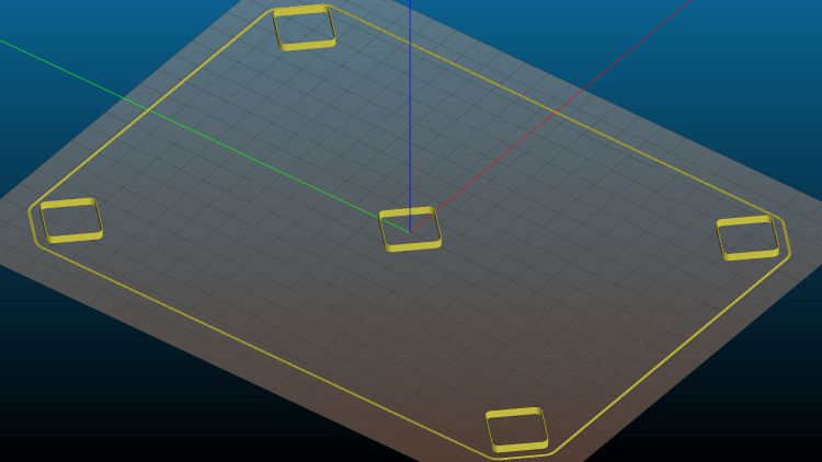
Because they’re well separated and only 3 mm tall, I set Slic3r to print them sequentially to eliminate a whole bunch of back-and-forth travel for each layer.
Print and measure the results:

The outer numbers come from the skirt around the whole platform in units of 0.01 mm: 22 → 0.22 mm. The five inner numbers are the eyeballometric average of four measurements across each square.
They came short enough that adding 0.25 mm to their height would improve the outcome. The scribbles in the upper right corner show the initial Z offset was -2.50 mm, which means -2.75 mm should do the trick; remember to save the new value in EEPROM with M500.
Print the same G-Code file with the new offset and measure:

Can’t get much closer than that!
The skirt gains only 0.1 mm for reasons unknown to me. It’s a good diagnostic tool for keeping an eye on the overall alignment without having to run more calibration squares, though.
Comparing the center squares (bottom layers facing each other in the middle) from the two sets shows the difference:

The bottom three layers got pretty well squashed with the previous offset. It’s missing about a full layer, although the nozzle wasn’t mashed flat / blocked against the platform. All the layers in the post-adjustment square look identical, as they should.
The wall thickness on the latter squares runs from 0.40 to 0.44 mm, with an eyeballometric average around 0.43, so tweaking the Extrusion Multiplier down by maybe 5% would be in order if I were being fussy.
Overall, not bad for a new setup!

Comments
One response to “Makergear M2: Platform Z=0 and Alignment Check”
[…] will crash your M2, because you haven’t relocated the Z-axis switch, haven’t calibrated Z=0 at the platform surface, and don’t put the XY=0 origin in the center of the […]