The Smell of Molten Projects in the Morning

Ed Nisley's Blog: Shop notes, electronics, firmware, machinery, 3D printing, laser cuttery, and curiosities. Contents: 100% human thinking, 0% AI slop.

Category: Software

General-purpose computers doing something specific

  • Bafang BBS02: Terry Head Tube Clip

    Bafang BBS02: Terry Head Tube Clip

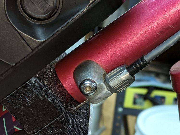
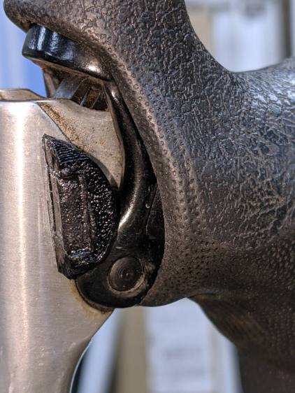
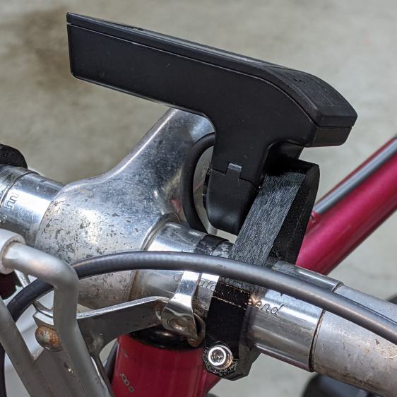
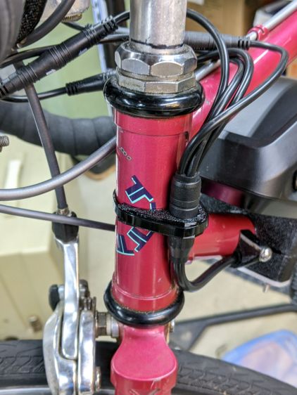
    The Bafang BBS02 runs a fat “harness cable” from the motor to the four handlebar components (two brake sensors, throttle, and display), with a lump covering the junction where the four smaller cables emerge. Securing the lump to the head tube seemed like a good way to keep the motion in the (presumably) more flexible smaller cables:
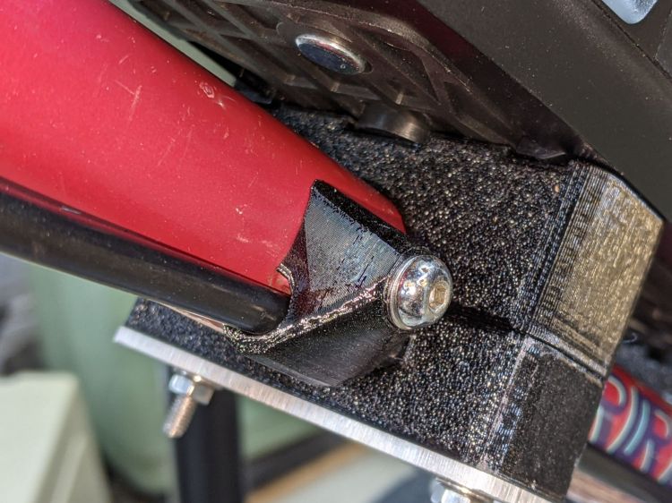
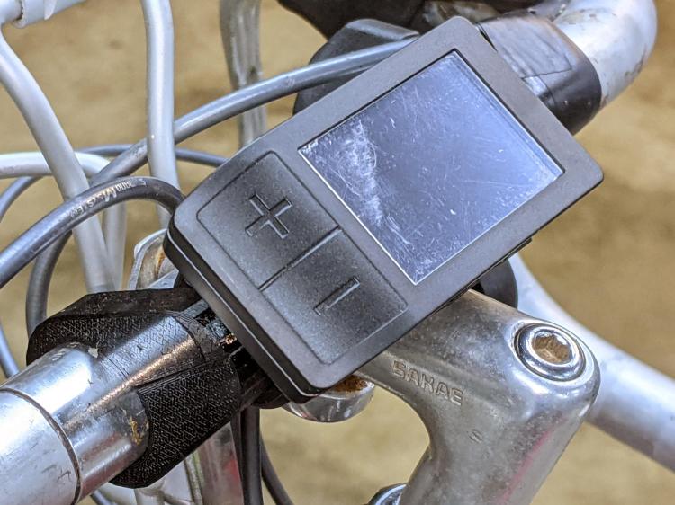
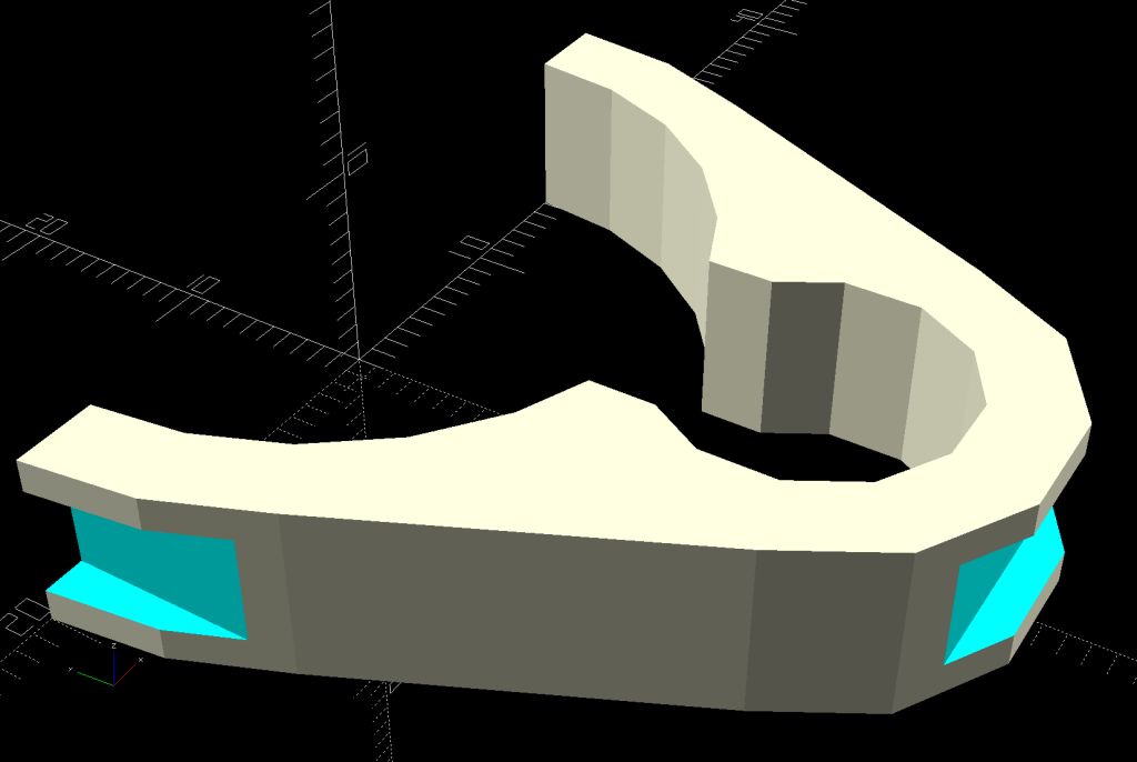
    Terry Bafang - headset cable clip - front
    Terry Bafang – headset cable clip – front

    From the rear:

    Terry Bafang - headset cable clip - rear
    Terry Bafang – headset cable clip – rear

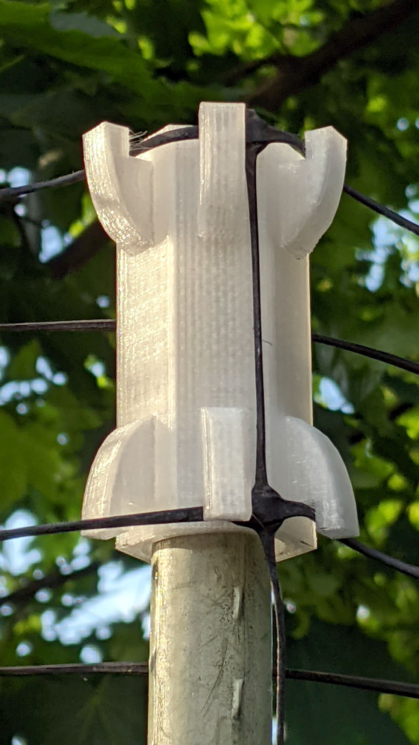
    I later bound the four connectors into a cluster using cable ties to further reduce the clutter and keep them from tapping the top tube.

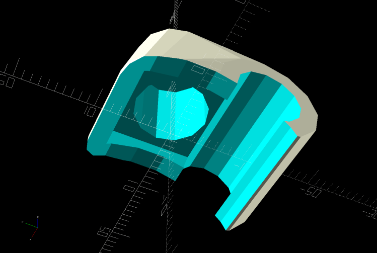
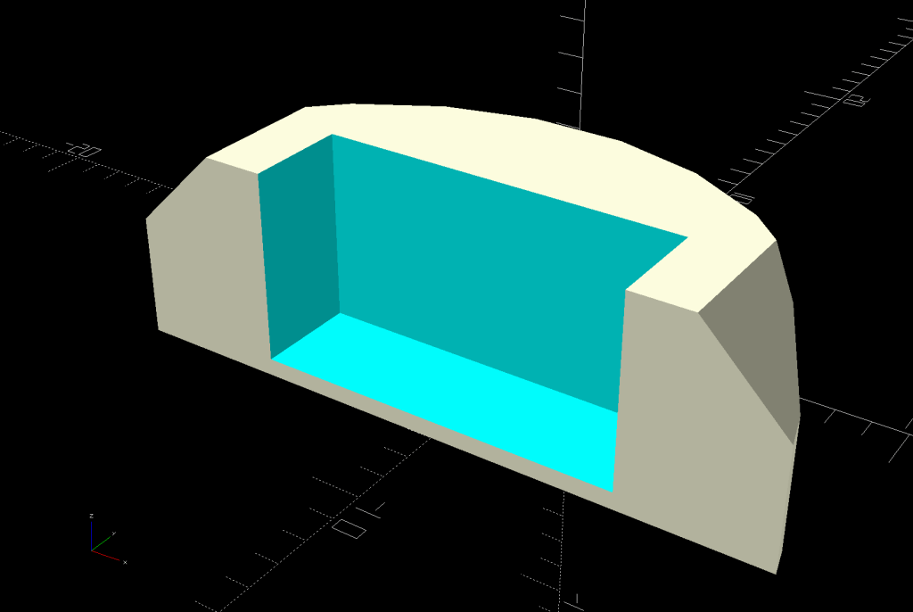
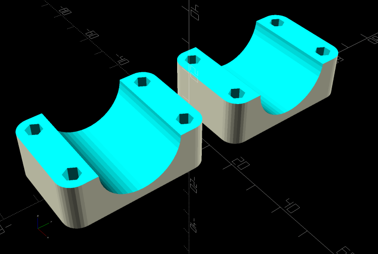
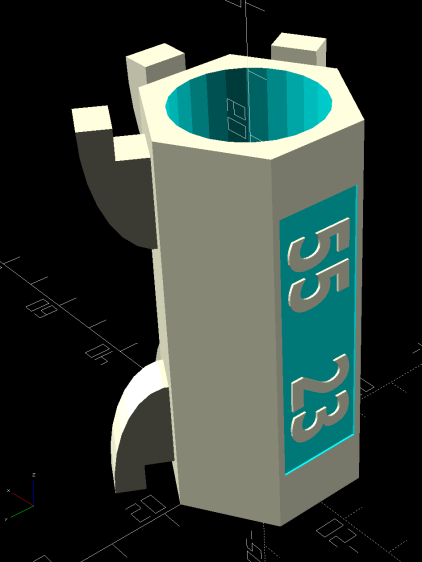
    The clip captures the cable tie in those indents:

    Terry - Bafang head tube clip - solid model
    Terry – Bafang head tube clip – solid model

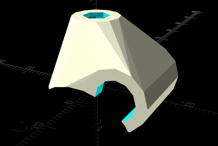
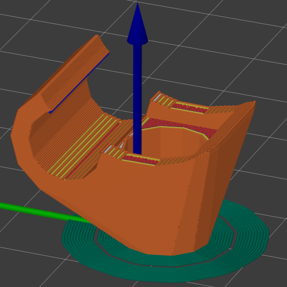
    The overhangs require easy cleanup with a square file to get rid of a few droopy threads. Avoid the temptation to print it standing up as an arch, because you want the perimeter threads to go around the whole thing, not across the thinnest sections. Trust me on this.

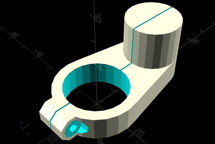
    The OpenSCAD source code:

    module HeadClip() {
    
    CableOD = Harness[OD];
    
        difference() {
            linear_extrude(height=HeadTube[LENGTH],convexity=10)
                difference() {
                    hull() {
                        circle(d=HeadTube[ID] + 2*WallThick,$fn=FrameSides);
                        translate([0,-(HeadTube[ID] + CableOD)/2])
                            rotate(180/(FrameSides/2))
                                circle(d=CableOD + 2*WallThick,$fn=FrameSides/2);
                    }
                    circle(d=HeadTube[ID] + HoleWindage,$fn=FrameSides);
                    translate([0,-(HeadTube[ID] + CableOD)/2])
                        rotate(180/(FrameSides/2))
                            circle(d=CableOD + HoleWindage,$fn=FrameSides/2);
                    translate([0,-HeadTube[ID]/2])
                        square(0.75*CableOD,center=true);
                    translate([0,HeadTube[ID]])
                        square(2*HeadTube[ID],center=true);
                }
            translate([0,-(HeadTube[ID]/2 + CableOD + WallThick - CableTie.z/2),HeadTube[LENGTH]/2])
                cube([HeadTube[ID],CableTie.z,CableTie.y],center=true);
    
           for (i=[-1,1])
                translate([i*(HeadTube[ID]/2 + WallThick - CableTie.z/2),0,HeadTube[LENGTH]/2])
                    cube([CableTie.z,HeadTube[ID],CableTie.y],center=true);
        }
    }
    

    I briefly thought of holding two pieces together around the head tube with M3 screws, but came to my senses: a cable tie is exactly what you want when holding a cable in place. Right?

  • Bafang BBS02: Terry Cable Stop Cap

    Bafang BBS02: Terry Cable Stop Cap

    The Terry Symmetry had shift cables running along the down tube, with cable housing stop bushings at the top:

    Terry Bafang - OEM shift stop
    Terry Bafang – OEM shift stop

    Without the front derailleur and with the wiring harness cable on the left side, a tidy cap seemed in order:

    Terry Bafang - shift stop cap
    Terry Bafang – shift stop cap

    The oversize passage give the cable a little flex room, although that’s probably unnecessary. I reused the original M5 screw, with a washer to spread the load.

    The solid model is basically a hull around some cylinders:

    Terry - Bafang shift cap - solid model
    Terry – Bafang shift cap – solid model

    The interior matches the stud brazed onto the downtube:

    Terry - Bafang shift cap - interior - solid model
    Terry – Bafang shift cap – interior – solid model

    The only practical way to build the thing required a brim stabilizing it on the platform:

    Terry - Bafang shift cap - slice preview
    Terry – Bafang shift cap – slice preview

    My usual 0.25 mm layers came out a bit crude on the vast overhang, but 0.15 mm layers worked fine.

    The OpenSCAD source code snippet:

    CapBlock = [18,18,16.5];
    
    module ShiftCap() {
    
    Rounding = 3.5;
    CapM = 3.0;
    StudBase = [12.5,12.5,4.5];
    Stud = [5.0,9.3,15.5];
    
        difference() {
            hull() {
                translate([0,0,CapBlock.z - 0.5])
                    PolyCyl(Washer5[OD],0.5,12);
                for (i=[-1,1], j=[-1,1])
                    translate([i*(CapBlock.x/2 - Rounding),j*(CapBlock.y/2 - Rounding),0])
                        sphere(r=Rounding,$fn=12);
                translate([-CapBlock.x/2,-Harness[ID]/2 - StudBase.y/2,StudBase.z/2])
                    rotate([0,90,0])
                        cylinder(d=Harness[ID] + 2*WallThick,h=CapBlock.x,$fn=12);
            }
    
            translate([0,0,-(FrameTube.z/2 - CapM)])
                Frame();
    
            PolyCyl(Screw5[ID],2*CapBlock.z,6);
    
            PolyCyl(Stud[OD],Stud[LENGTH],12);
    
            translate([0,0,StudBase.z/2])
                cube(StudBase,center=true);
    
            translate([0,-StudBase.y/2,StudBase.z/2])
                cube(StudBase + [0,-StudBase.y/2,0],center=true);
    
           translate([-CapBlock.x,-Harness[ID]/2 - StudBase.y/2,StudBase.z/2])
                rotate([0,90,0])
                    cylinder(d=1.5*Harness[ID],h=2*CapBlock.x,$fn=12);
    
        }
    }
    

    Of course, I needed three tries to get the correct dimensions, but that’s what rapid prototyping is all about.

  • Bafang BBS02: Terry Brake Sensor

    Bafang BBS02: Terry Brake Sensor

    The old-school “aero” brake levers on Gee’s Terry Symmetry bike have rubberoid cushion covers, so I slid the Bafang brake sensors inside:

    Terry Bafang brake sensor - front
    Terry Bafang brake sensor – front

    They make the grips somewhat wider, but I can’t figure out a less destructive way of installing the things.

    I glued the magnet inside a holder contoured to fit the space available:

    Terry - Bafang brake sensor - solid model
    Terry – Bafang brake sensor – solid model

    Knocking the corners off makes it much more finger-friendly.

    It’s unobtrusive with the handle released:

    Terry Bafang brake sensor - released
    Terry Bafang brake sensor – released

    When you squeeze the lever, your fingers are nowhere near the magnet:

    Terry Bafang brake sensor - pulled
    Terry Bafang brake sensor – pulled

    The lower edge actually slides along the brake lever housing without touching, but it’s a near thing.

    Those are the same magnets I used for the Bafang brake sensors on Mary’s Tour Easy, once again aligned to aim the strongest volume of the magnetic field toward the sensor. The brake sensors activate just before the pads touch the rims and release with the magnets a few millimeters away from the sensors.

    A complete coat of JB Plastic Bonder urethane adhesive covers each magnet to both isolate it from the weather and conceal the fact that they’re recycled from a power toothbrush.

    Now that I know they work in this position, I must ease adhesive underneath the sensors so they don’t move around under normal hand pressure.

    The OpenSCAD source code snippet:

    module BrakeMagnet() {
    
        Magnet = [10.5,3.0,5.5];
        Plate = 2*ThreadThick;
        BrakeRad = 10.0;            // brake handle curve Radius
        Holder = [2*BrakeRad,7.0,Magnet.z + Plate];
    
    
        difference() {
            intersection() {
                translate([0,-BrakeRad,0])
                    rotate(180/24)
                        cylinder(r=BrakeRad,h=Holder.z,$fn=24);
                translate([0,BrakeRad - Holder.y,Holder.z/2])
                    cube([2*BrakeRad,2*BrakeRad,Holder.z],center=true);
                translate([0,0,-2*BrakeRad/sqrt(2) + Holder.z - 3.0 + BrakeRad])
                    rotate([0,45,0])
                        cube(2*[BrakeRad,2*BrakeRad,BrakeRad],center=true);
            }
            translate([0,Magnet.y/2 - Holder.y - Protrusion/2,Magnet.z/2 + Plate + Protrusion/2])
                cube(Magnet + [0,Protrusion,Protrusion],center=true);
        }
    
    }
    

  • Bafang BBS02: Drop-bar Display Adapter

    Bafang BBS02: Drop-bar Display Adapter

    All of the Bafang BBS02 displays have a compression clamp intended for more-or-less standard 22.2 mm handlebars, as found on typical upright BMX-ish bikes suitable for conversion to e-bikes and, oddly, our Tour Easy recumbents. My friend’s bike has drop-bar handlebars with a 25.4 mm (yes, exactly 1 inch) center section that just isn’t going to fit through that hole.

    The least awful solution involved summoning an adapter from the vasty digital deep:

    Display adapter mount - solid model
    Display adapter mount – solid model

    The hole clamps around the handlebar with an M3 SHCS pulling it snug and the display clamps around the peg to hold everything together:

    Bafang Display adapter - front view
    Bafang Display adapter – front view

    There’s not much to see from the side:

    Bafang Display adapter - left view
    Bafang Display adapter – left view

    Those scuffs arrived on the protective plastic film!

    The OpenSCAD source code includes some cruft from an idea that didn’t work out quite right:

    HandlebarMax = 1*inch;                      // middle handlebar diameter
    HandlebarMin = 24.0;                        //  .. tape section
    
    BafangClampID = 22.3;                       // new handlebar diameter
    
    
    … snippage …
    
    // Handlebar mount for controller
    
    module DispMount() {
    
    ClampRing = [HandlebarMax,HandlebarMax + 2*WallThick,10.0];
    ClampOffset = (HandlebarMax + BafangClampID)/2 + 6.0;
    
    DispStudLenth = 16.5;
    
    NumSides = 24;
    
    Tilt = 0*atan2((ClampRing[OD] - BafangClampID)/2,ClampOffset);
    echo(str("Tilt: ",Tilt));
    
        difference() {
            union() {
                hull() {
                    cylinder(d=ClampRing[OD],h=ClampRing[LENGTH],$fn=NumSides);
                    translate([0,ClampOffset,0])
                        cylinder(d=BafangClampID,h=ClampRing[LENGTH],$fn=NumSides);
                }
                translate([0,ClampOffset,0])
                    cylinder(d=BafangClampID,h=ClampRing[LENGTH] + DispStudLenth,$fn=NumSides);
                translate([-ClampRing[ID]/4,-(ClampRing[OD]/2),ClampRing[LENGTH]/2])
                    rotate([0,90,0]) rotate(180/8)
                        cylinder(d=ClampRing[LENGTH]/cos(180/8),h=ClampRing[ID]/2,$fn=8);
            }
            cube([Kerf,4*ClampOffset,4*DispStudLenth],center=true);
            translate([0,0,-Protrusion])
                cylinder(d=ClampRing[ID],h=ClampRing[LENGTH] + 2*Protrusion,$fn=NumSides);
            translate([-ClampRing[ID]/2,-(ClampRing[OD]/2),ClampRing[LENGTH]/2])
                rotate([0,90,0]) rotate(180/8)
                    PolyCyl(Screw3[ID],ClampRing[ID],8);
            for (i=[-1,1])
                translate([i*ClampRing[ID]/4,-(ClampRing[OD]/2),ClampRing[LENGTH]/2])
                    rotate([0,i*90,0]) rotate(180/8)
                        PolyCyl(Washer3[OD],ClampRing[ID],$fn=8);
    
            translate([-5,25,EmbossDepth/2 - Protrusion/2])
                rotate(Tilt)
                    cube([4.5,21.5,EmbossDepth + Protrusion],center=true);
    
        }
    
        translate([-5,25,0])
            linear_extrude(height=EmbossDepth)
                rotate(90 + Tilt) mirror([0,1,0])
                  text(text="KE4ZNU",size=3.3,spacing=1.05,font="Bitstream Vera Sans:style=Bold",
                       halign="center",valign="center");
    
    }
    

    It’s rock-solid stable: pushing the buttons doesn’t budge it in the least.

  • Dripworks Mainline Pipe Clamp

    Dripworks Mainline Pipe Clamp

    This is laid in against a need I hope never occurs:

    Dripworks 0.75 inch pipe clamp
    Dripworks 0.75 inch pipe clamp

    It’s intended to clamp around one of the Dripworks mainline pipes carrying water from the pressure regulator to the driplines in the raised beds, should an errant shovel or fork find the pipe.

    It descends from a long line of soaker hose clamps, with a 25 mm ID allowing for a silicone tape wrap as a water barrier.

    The solid model has no surprises:

    Dripworks Mainline Clamp - build view
    Dripworks Mainline Clamp – build view

    The OpenSCAD source code as a GitHub Gist:

    // Dripworks 3/4 inch mainline clamp
    // Ed Nisley KE4ZNU 2021-06
    Layout = "Build"; // [Hose,Block,Show,Build]
    HoseOD = 25.0;
    TestFit = false; // true to build test fit slice from center
    //- Extrusion parameters must match reality!
    /* [Hidden] */
    ThreadThick = 0.25;
    ThreadWidth = 0.40;
    HoleWindage = 0.2;
    Protrusion = 0.1; // make holes end cleanly
    inch = 25.4;
    function IntegerMultiple(Size,Unit) = Unit * ceil(Size / Unit);
    ID = 0;
    OD = 1;
    LENGTH = 2;
    //———-
    // Dimensions
    // Hose lies along X axis
    Hose = [200,HoseOD,HoseOD]; // X = longer than anything else
    NumScrews = 2; // screws along each side of cable
    WallThick = 3.0; // Thinnest printed wall
    PlateThick = 1.5; // Stiffening plate thickness
    // 8-32 stainless screws
    Screw = [4.1,8.0,50.0]; // OD = head LENGTH = thread length
    Washer = [4.4,9.5,1.0];
    Nut = [4.1,9.7,3.3];
    Block = [30.0,Hose.y + 2*Washer[OD],HoseOD + 2*WallThick]; // overall splice block size
    echo(str("Block: ",Block));
    ScrewMinLength = Block.z + 2*PlateThick + 2*Washer.z + Nut.z; // minimum screw length
    echo(str("Screw min length: ",ScrewMinLength));
    Kerf = 1.0; // cut through middle to apply compression
    CornerRadius = Washer[OD]/2;
    ScrewOC = [(Block.x – 2*CornerRadius) / (NumScrews – 1),
    Block.y – 2*CornerRadius,
    2*Block.z // ensure complete holes
    ];
    echo(str("Screw OC: x=",ScrewOC.x," y=",ScrewOC.y));
    //———————-
    // Useful routines
    module PolyCyl(Dia,Height,ForceSides=0) { // based on nophead's polyholes
    Sides = (ForceSides != 0) ? ForceSides : (ceil(Dia) + 2);
    FixDia = Dia / cos(180/Sides);
    cylinder(d=(FixDia + HoleWindage),h=Height,$fn=Sides);
    }
    // Hose shape
    // This includes magic numbers measured from reality
    module HoseProfile() {
    NumSides = 12*4;
    rotate([0,-90,0])
    translate([0,0,-Hose.x/2])
    resize([Hose.z,Hose.y,0])
    cylinder(d=Hose.z,h=Hose.x,$fn=NumSides);
    }
    // Outside shape of splice Block
    // Z centered on hose rim circles, not overall thickness through center ridge
    module SpliceBlock() {
    difference() {
    hull()
    for (i=[-1,1], j=[-1,1]) // rounded block
    translate([i*(Block.x/2 – CornerRadius),j*(Block.y/2 – CornerRadius),-Block.z/2])
    cylinder(r=CornerRadius,h=Block.z,$fn=4*8);
    for (i = [0:NumScrews – 1], j=[-1,1]) // screw holes
    translate([-(Block.x/2 – CornerRadius) + i*ScrewOC.x,
    j*ScrewOC.y/2,
    -(Block.z/2 + Protrusion)])
    PolyCyl(Screw[ID],Block.z + 2*Protrusion,6);
    cube([2*Block.x,2*Block.y,Kerf],center=true); // slice through center
    }
    }
    // Splice block less hose
    module ShapedBlock() {
    difference() {
    SpliceBlock();
    HoseProfile();
    }
    }
    //———-
    // Build them
    if (Layout == "Hose")
    HoseProfile();
    if (Layout == "Block")
    SpliceBlock();
    if (Layout == "Show") {
    difference() {
    SpliceBlock();
    HoseProfile();
    }
    color("Green",0.25)
    HoseProfile();
    }
    if (Layout == "Build") {
    SliceOffset = TestFit && !(NumScrews % 2) ? ScrewOC.x/2 : 0;
    intersection() {
    translate([SliceOffset,0,Block.z/4])
    if (TestFit)
    cube([ScrewOC.x/2,4*Block.y,Block.z/2],center=true);
    else
    cube([4*Block.x,4*Block.y,Block.z/2],center=true);
    union() {
    translate([0,0.6*Block.y,Block.z/2])
    ShapedBlock();
    translate([0,-0.6*Block.y,Block.z/2])
    rotate([0,180,0])
    ShapedBlock();
    }
    }
    }

  • Sticky Trap Screen Frames

    Sticky Trap Screen Frames

    The objective being to reduce the number of onion maggots in Mary’s Vassar Farm plot without chemical agents, I conjured sticky trap screen frames from the vasty digital deep:

    Sticky Trap - first production run
    Sticky Trap – first production run

    Each one contains half a sheet of yellow sticky plastic, which is easy enough to cut before peeling off the protective covering sheets. The cage is half-inch galvanized hardware cloth snipped with hardened diagonal cutters. A bead of acrylic adhesive around the base holds the cage in place

    Although you can deploy sticky sheets without cages, they tend to attract and affix beneficial critters: butterflies, small birds, furry critters, toads, gardeners, and the like. We don’t know how effective the cages will be, but they seemed better than nothing.

    They mount on ski poles cut in half:

    Sticky Trap - ski pole installed
    Sticky Trap – ski pole installed

    And on fence posts around the perimeter:

    Sticky Trap - angle bracket installed
    Sticky Trap – angle bracket installed

    To my untrained eye, some of those doomed critters are, indeed, onion maggot flies. The rest seem to be gnats and other nuisances, so IMO we’re applying population pressure in the right direction.

    Each base-and-cap frame takes about three hours to print, so I did them one at a time over the course of a few days while applying continuous product improvement.

    The sheets rest on small V blocks intended to keep them centered within the cage:

    Sticky Sheet Cage - angle bracket - solid model
    Sticky Sheet Cage – angle bracket – solid model

    The ski pole attachment must build with the cap on top, but it bridges well enough for the purpose:

    Sticky Sheet Cage - ski pole - solid model
    Sticky Sheet Cage – ski pole – solid model

    The overhanging hooks on the blocks (just barely) engage the grid to keep the lid in place, while remaining short enough to not droop too badly. You could probably delete the hooks from the bottom plate, but they align the cage while the adhesive cures.

    The sheets tend to bend in the middle, so I’ll stick a thin slat or two vertically to keep them straight.

    The OpenSCAD source code as a GitHub Gist:

    // Sticky Sheet Cage
    // Ed Nisley KE4ZNU May 2021
    Layout = "Build"; // [Build, Show, Cap, Attachment]
    Bracket = "Ski"; // [Angle, Ski, Post]
    //- Extrusion parameters must match reality!
    /* [Hidden] */
    ThreadThick = 0.25;
    ThreadWidth = 0.40;
    HoleWindage = 0.2;
    Protrusion = 0.1; // make holes end cleanly
    inch = 25.4;
    ID = 0;
    OD = 1;
    LENGTH = 2;
    function IntegerMultiple(Size,Unit) = Unit * ceil(Size / Unit);
    //———————-
    // Dimensions
    Sheet = [1,100,150]; // sticky sheet
    Grid = 0.5*inch;
    Cage = [2*Grid + 5.0, 8*Grid + 5.0, 12*Grid + 2.0]; // grid wire cage bent around sheet
    CageRad = 2.5; // wire bending radius
    CageThick = 2.0; // grid thickness
    WallThick = 3.0; // min wall and bottom thickness
    Recess = 5.0; // inset to capture cage edge
    Plate = [Cage.x,Cage.y,Recess] + [2*WallThick,2*WallThick,WallThick];
    PlateRad = 5.0;
    SkiPole = [20.0,20.0 + 2*WallThick,50];
    AnglePlate = [30,30,50];
    ScrewClear = 5.0;
    BuildGap = 5.0;
    //———————-
    // Useful routines
    module PolyCyl(Dia,Height,ForceSides=0) { // based on nophead's polyholes
    Sides = (ForceSides != 0) ? ForceSides : (ceil(Dia) + 2);
    FixDia = Dia / cos(180/Sides);
    cylinder(r=(FixDia + HoleWindage)/2,
    h=Height,
    $fn=Sides);
    }
    //———————-
    // Pieces
    module Cap() {
    union() {
    difference() {
    hull()
    for (i=[-1,1], j=[-1,1])
    translate([i*(Plate.x/2 – PlateRad),j*(Plate.y/2 – PlateRad),0])
    cylinder(r=PlateRad,h=Plate.z,$fn=12);
    translate([0,0,Plate.z – Recess])
    hull()
    for (i=[-1,1], j=[-1,1])
    translate([i*(Cage.x/2 – CageRad),j*(Cage.y/2 – CageRad),0])
    cylinder(r=CageRad,h=Plate.z,$fn=12);
    }
    difference() {
    Strut = Cage.x – 2*CageThick;
    Latch = [Cage.x,WallThick,0.75*Plate.z];
    union() {
    for (j=[-1,1])
    translate([0,j*2.5*Grid,Plate.z])
    cube([Strut,WallThick,2*Plate.z],center=true);
    for (j=[-1,1])
    translate([0,j*2.5*Grid,2*Plate.z – Latch.z/2])
    cube(Latch,center=true);
    }
    translate([0,0,2*Plate.z + (Cage.z – Sheet.z)/4])
    rotate([0,45,0])
    cube([Strut/sqrt(2),Plate.y,Strut/sqrt(2)],center=true);
    }
    }
    }
    module Attachment() {
    if (Bracket == "Angle") {
    translate([0,Plate.y/2,0])
    rotate(45)
    difference() {
    union() {
    cube(AnglePlate,center=false);
    rotate(-45)
    translate([0,WallThick,Plate.z/2])
    cube([Plate.x – 2*PlateRad,4*WallThick,Plate.z],center=true);
    }
    translate([WallThick,WallThick,-Protrusion])
    cube(AnglePlate + [0,0,2*Protrusion],center=false);
    translate([AnglePlate.x/2,-Protrusion,2*AnglePlate.z/3])
    rotate([-90,0,0])
    PolyCyl(ScrewClear,2*AnglePlate.x,6);
    translate([-Protrusion,AnglePlate.x/2,1*AnglePlate.z/3])
    rotate([90,0,90])
    PolyCyl(ScrewClear,2*AnglePlate.x,6);
    }
    }
    else if (Bracket == "Ski") {
    translate([0,Plate.y/2 + SkiPole[OD]/2,0])
    difference() {
    union() {
    PolyCyl(SkiPole[OD],SkiPole[LENGTH],24);
    translate([0,-3*WallThick,Plate.z/2])
    cube([Plate.x – 2*PlateRad,4*WallThick,Plate.z],center=true);
    }
    translate([0,0,-2*WallThick])
    PolyCyl(SkiPole[ID],SkiPole[LENGTH],24);
    }
    }
    }
    //———————-
    // Build it
    if (Layout == "Cap")
    Cap();
    if (Layout == "Attachment") {
    Attachment();
    }
    if (Layout == "Show") {
    translate([0,0,Sheet.z/2 + Plate.z])
    color("Yellow")
    cube(Sheet,center=true);
    Cap();
    Attachment();
    translate([0,0,Sheet.z + 2*Plate.z])
    rotate([180,0,0])
    Cap();
    }
    if (Layout == "Build") {
    translate([-(Plate.x/2 + BuildGap),0,0]) {
    Cap();
    Attachment();
    }
    translate([(Plate.x/2 + BuildGap),0,0])
    Cap();
    }

  • Deer Fence Hangers

    Deer Fence Hangers

    For what should be obvious reasons, we armored Mary’s “kitchen garden” with buried concrete blocks and deer fence. I secured the fence to 7 foot plastic-coated steel-core posts strapped to shorter stakes supporting the lower wire fence, using cable ties we both knew wouldn’t survive exposure to the sun.

    As part of the spring garden prep, I summoned proper supports from the vasty digital deep:

    Deer Fence Hanger - Build view
    Deer Fence Hanger – Build view

    The general idea is to plunk one atop each post and tangle wrap the netting through the hooks, thusly:

    Deer Fence Hanger - installed
    Deer Fence Hanger – installed

    The garden looks like we killed an entire chess set and impaled their carcasses as a warning to others of their kind, but the fence now hangs neatly from the top of the posts rather than drooping sadly.

    Each one of those things takes nigh onto two hours to emerge from the M2, so I printed them one by one over the course of a few days while making continuous product improvements.

    The “natural” PETG isn’t UV stabilized, either, but it ought to last longer than those little bitty nylon cable ties. We shall see.

    The OpenSCAD source code as a GitHub Gist:

    // Deer Fence Hangers
    // Ed Nisley KE4ZNU May 2021
    Layout = "Show"; // [Build, Show, Cap, Hook]
    // net grid spacing
    NetOC = 55.0; // [40.0:5.0:70.0]
    // stake OD
    PoleDia = 23.0; // [20.0:30.0]
    //- Extrusion parameters must match reality!
    /* [Hidden] */
    ThreadThick = 0.25;
    ThreadWidth = 0.40;
    HoleWindage = 0.2;
    Protrusion = 0.1; // make holes end cleanly
    inch = 25.4;
    ID = 0;
    OD = 1;
    LENGTH = 2;
    function IntegerMultiple(Size,Unit) = Unit * ceil(Size / Unit);
    //———————-
    // Dimensions
    Notch = 5.0; // hook engagement
    WallThick = 3.0; // min wall and end thickness
    Shell = [PoleDia,PoleDia + 2*WallThick,NetOC + 2*Notch];
    HookBlock = [10.0,Shell.y/4,2*Notch]; // hanger inside length
    LegendBlock = [0.7*Shell.z,Shell.y/2,2*ThreadThick]; // legend size
    //———————-
    // Useful routines
    module PolyCyl(Dia,Height,ForceSides=0) { // based on nophead's polyholes
    Sides = (ForceSides != 0) ? ForceSides : (ceil(Dia) + 2);
    FixDia = Dia / cos(180/Sides);
    cylinder(r=(FixDia + HoleWindage)/2,
    h=Height,
    $fn=Sides);
    }
    //———————-
    // Pieces
    module Hook() {
    //%Cap();
    translate([Shell[OD]/2 – Protrusion,HookBlock.y/2,0])
    rotate([90,0,0])
    linear_extrude(height=HookBlock.y)
    difference() {
    scale([1,2])
    intersection() {
    circle(r=HookBlock.x);
    square(HookBlock.x,center=false);
    }
    square(Notch,center=false);
    }
    }
    module Cap() {
    difference() {
    rotate(180/6)
    PolyCyl(Shell[OD],Shell[LENGTH],6);
    translate([0,0,-WallThick])
    rotate(180/24)
    PolyCyl(Shell[ID],Shell[LENGTH],24);
    translate([-Shell[OD]/2,0,Shell[LENGTH]/2])
    rotate([0,90,0])
    cube(LegendBlock,center=true);
    }
    translate([-(Shell[OD]/2 – LegendBlock.z/2),0,Shell[LENGTH]/2])
    rotate([0,-90,0])
    resize(0.8*LegendBlock,auto=[true,true,false])
    linear_extrude(height=LegendBlock.z)
    text(text=str(NetOC," ",PoleDia),
    size=6,spacing=1.00,font="Bitstream Vera Sans:style=Bold",
    halign="center",valign="center");
    }
    module Hanger() {
    Cap();
    for (k=[0,1])
    translate([0,0,k*Shell.z])
    for (a=[-1:1])
    rotate([k*180,0,a*60])
    Hook();
    }
    //———————-
    // Build it
    if (Layout == "Cap")
    Cap();
    if (Layout == "Hook")
    Hook();
    if (Layout == "Show")
    Hanger();
    if (Layout == "Build")
    translate([0,0,Shell[LENGTH]])
    rotate([180,0,0])
    Hanger();