The Smell of Molten Projects in the Morning

Ed Nisley's Blog: Shop notes, electronics, firmware, machinery, 3D printing, laser cuttery, and curiosities. Contents: 100% human thinking, 0% AI slop.

Category: Machine Shop

Mechanical widgetry

  • Nissan Fog Lamp: RGB LED “Bulb”

    Nissan Fog Lamp: RGB LED “Bulb”

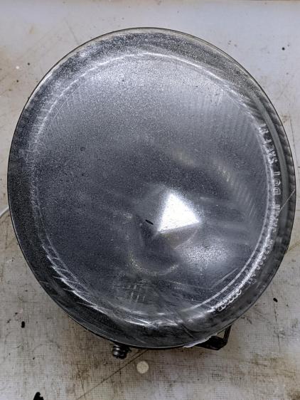
    After cleaning the fog lamp lens enough to be encouraging, I made an LED “bulb” from four WS2812 RGB pixels:

    Nissan Fog Lamp - LED bulb standup
    Nissan Fog Lamp – LED bulb standup

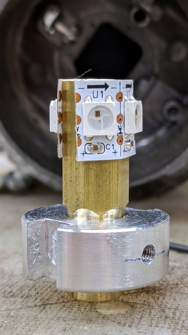
    The small threaded hole has an M3 setscrew to let the brass post slide up & down to adjust the LED position inside the fog lamp’s reflector.

    Despite my poor experience with the PCB-based WS2812 LEDs, the strip-mounted ones have been ticking along in the hard drive platter lamp basically forever, at least after I tamped down the heat problem.

    The brass hex rod has plenty of thermal conductivity, particularly clamped into an aluminum disk connected more-or-less well to the fog lamp’s base.

    Nissan Fog Lamp - RGB LED lamp
    Nissan Fog Lamp – RGB LED lamp

    The two short wires linking the two LED strips (the purple wire is data into the first LED) hold them in place around the hex, despite their desire to straighten out, pull free of their adhesive, and fall off.

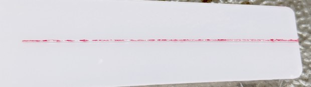
    The general idea was to put the LEDs at about the same level as the halogen bulb filament, thereby spreading enough light to fill the reflector housing:

    Nissan Fog Lamp - LED vs halogen
    Nissan Fog Lamp – LED vs halogen

    I drilled a hole through the hex as a cable “conduit”, turned the end into a nice rod, then machined a stub of aluminum to fit:

    Nissan Fog Lamp - parting off LED base
    Nissan Fog Lamp – parting off LED base

    A pair of slots milled along the sides of the aluminum disk fit the housing’s locating features:

    Nissan Fog Lamp - LED bulb trial fit
    Nissan Fog Lamp – LED bulb trial fit

    Nissan used an elaborate spring latch to clamp the halogen bulb’s sheet-metal base in place, but its 50 mil wire didn’t have nearly enough give for my chunky aluminum disk. My version of a spring latch came from a length of 24 mil music wire, which definitely beats the epoxy I was planning to use.

    Heat transfer seems to be a non-issue, as the LEDs get barely warm to the touch. Until they drop dead, I’ll assume it’s all good in there.

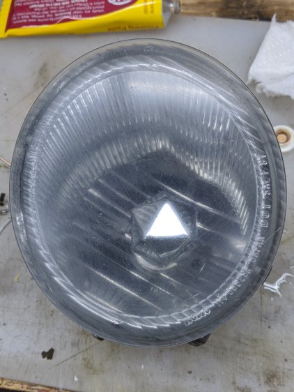
    Two screws hold the lens in place, but the collision seems to have stripped their grip on the plastic and they didn’t un-screw:

    Nissan Fog Lamp - lens retaining screw
    Nissan Fog Lamp – lens retaining screw

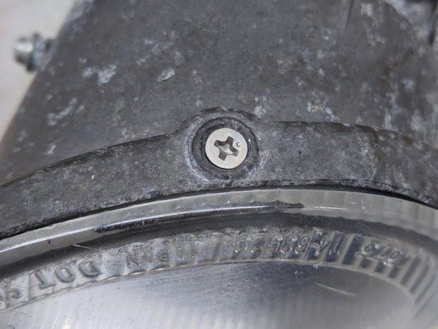
    Jamming a utility knife blade under the screw head and prying upward while turning the screwdriver persuaded them out of their sockets, after which the lens popped out of its form-fitted silicone gasket with surprisingly little effort:

    Nissan Fog Lamp - reflector stains
    Nissan Fog Lamp – reflector stains

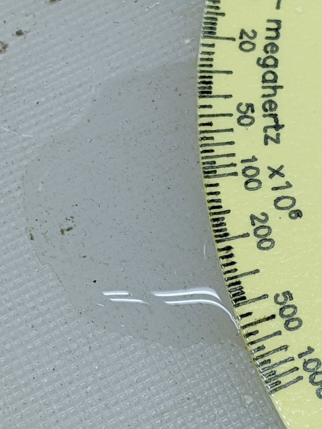
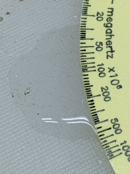
    The lamp spent a week or so beside the road, out in the weather, and shipped a few drops of rainwater through the rectangular hole under the spring latch anchor. Some delicate cotton-swab action removed most of the grime without too much damage, but the reflective film on those corrugations won’t ever be the same again.

    Now it’s just a simple matter of software …

  • Tek Circuit Computer: Water Test

    Tek Circuit Computer: Water Test

    So the question came up: “Exactly what happens when one of those things gets wet?”

    Which obviously requires an experiment:

    Laminated Tek CC vs Water - start
    Laminated Tek CC vs Water – start

    That’s the mis-cut top deck revealing why GRBL really needs four digits after the decimal point, but, other than that, it’s perfectly representative of the genre: heavy paper, good ink, nicely laminated in plastic.

    Prediction: water should seep into the paper, dissolve the ink, maybe delaminate the plastic, and generally make a mess.

    Which is exactly what happens:

    Laminated Tek CC vs Water - finish
    Laminated Tek CC vs Water – finish

    User Advisory: your shiny new Homage Tektronix Circuit Computer is not waterproof, so don’t use it in the sauna!

  • Nissan Fog Lamp: Salvage & Lens Clearing

    Nissan Fog Lamp: Salvage & Lens Clearing

    The debris field from a recent high-energy collision with a utility pole just north of Red Oaks Mill included another attractive hunk of jewelry:

    Nissan Fog Lamp - as found
    Nissan Fog Lamp – as found

    I asked the guy who runs the towing service across the intersection if this was a “high-performance car / low-performance driver” situation. He said “Nah, the car was a piece of crap.” It apparently collided with the pole after pulling out of the adjacent gas station with entirely too much foot on the throttle; the young driver was last seen having considerable difficulty with a field sobriety test.

    Anyhow, the labeling suggests it’s the right-side fog light from a Nissan car.

    After removing various shattered plastic mounts and scrubbing off the obvious dirt, the lens didn’t look much better:

    Nissan Fog Lamp - as-found lens
    Nissan Fog Lamp – as-found lens

    The bright triangle is one facet of the hood over the 55 W halogen bulb. The lens seems to be covered with a scattershot coat of gray spray paint or primer, rather than ordinary road grime, applied with surprising uniformity over the entire surface.

    A quick wet-sand operation with 400 through 3000 grit paper, then some Simichrome, cleaned it up pretty well:

    Nissan Fog Lamp - semi-cleared lens
    Nissan Fog Lamp – semi-cleared lens

    Repeating the whole process, this time with a vigorous circular motion:

    Nissan Fog Lamp - cleared lens
    Nissan Fog Lamp – cleared lens

    It’s definitely got a used-car finish: nice polish over deep gouges.

    Look closely to see 400 grit diagonal scratches headed upward to the right; I must use 600 or 800 grit paper between the 400 and 1000. I don’t care about optical clarity, just knocking back the worst of the damage will suffice.

    Methinks it would look pretty with internal RGB LED lighting, although the optics are obviously set up for a halogen filament just under the edge of the internal hood. If I get it just right, the thing could project a beam across the room …

  • Maximum 3D Printing Speed

    Maximum 3D Printing Speed

    With everybody 3D printing masks these days, the question of “how fast can you print” came up on the Makergear forum.

    Here’s my opinion:

    The fundamental limit comes from the heater’s ability to bring cold plastic up to extrusion temperature inside the 20 mm hot zone.

    Using airscape’s example, the extruded thread is 0.5 mm thick × 0.8 mm wide = 0.4 mm², so laying down that thread at 50 mm/s means the extruder is heating plastic at 20 mm³/s and is “pushing it with PLA”.

    In round numbers, normal printing speeds with a normal nozzle and normal plastics runs around 10 mm³/s, so a practical upper limit is probably around 15 mm³/s.

    As far as thread size goes, the diameter of the flat area around the nozzle orifice sets the maximum thread width, because the nozzle must compress the thread against the previous layer. If the thread is wider than the nozzle, the gooey plastic curls up around the sides of the nozzle and doesn’t bond well. The rule of thumb is to round up the orifice diameter to the next convenient number:

    • 0.35 mm nozzle → 0.4 mm thread
    • 0.75 mm nozzle → 0.8 mm thread

    The maximum thread (= layer) thickness should be about 60% of the thread width, which is why a 0.8 mm wide thread calls for a 0.5 mm layer thickness.

    Assuming the extruder can heat 15 mm³/s of plastic, the maximum printing speed will be 15 mm³/s / 0.4 mm² = 37.5 mm/s: comfortably under airscape’s “pushing it” 50 mm/s.

    A visualization may be helpful:

    Extrusion Dimensions
    Extrusion Dimensions

    Aaaaand, as always, calibrate the Extrusion Multiplier for whatever conditions you’re using to ensure the slicer and the hardware agree on how much plastic is coming out of the nozzle.

  • Backyard Utility Pole: Anchor Clamp Hardware

    Backyard Utility Pole: Anchor Clamp Hardware

    This also appeared while clearing the forsythia:

    Pole anchor - abandoned in place
    Pole anchor – abandoned in place

    It’s the guy line anchor for the fallen utility pole, abandoned in place when the crew installed the new pole.

    The rod turned freely in its underground anchor, but the nut is apparently frozen to the rod. I deployed the bolt cutter on the cable and hauled the carcass into the Basement Shop:

    Pole anchor - nut loosening
    Pole anchor – nut loosening

    Steeping the nuts with Kroil for a few hours relaxed them enough to submit to gentle suasion, whereupon the cable sproinged as the last nut released the clamping force:

    Pole anchor - hardware
    Pole anchor – hardware

    As far as I can tell, the clamp hardware dates back to the pole’s original installation in 1940 and is in fine, if not pristine, shape.

    The bolt shanks have an oval section matching the holes in the plate, so the bolts don’t turn and the crew needs only one wrench. They don’t make ’em like they used to!

    I have no idea what I’ll do with these things, but they’re entirely too nice for the steel recycling bucket.

  • Tek Circuit Computer: Cursor Hairline Filling

    Tek Circuit Computer: Cursor Hairline Filling

    Some cleanup and a fresh layer of double-sided tape gives the cursor milling fixture plenty of adhesion:

    Tek CC - Cursor blank on fixture
    Tek CC – Cursor blank on fixture

    This time, I diamond-scribed three PETG cursors through the transparent protective film, with two / four / six passes:

    Tek CC - Cursor hairline filling
    Tek CC – Cursor hairline filling

    It’s not a Purple Crayon, but it suffices for my simple needs.

    Scribbling a (soft!) lacquer crayon over transparent plastic still scuffs the pristine surface around the engraved line, so I tried scribbling the six-pass cursor before peeling the film, as shown above. Unfortunately, the film shreds left around the line either prevent a clean fill or pull the paint out of the ditch as the film peels back:

    Tek CC - Cursor lacquer fill
    Tek CC – Cursor lacquer fill

    Peeling the film and scribbling ever-so-gently left a more complete line, but, if you look very closely (perhaps opening the image in a new tab for more dots), you can see the scuffs left by the scribbles on either side of the line:

    Tek CC - Cursor 2 4 6 scribes
    Tek CC – Cursor 2 4 6 scribes

    When seen from the other side against laminated decks, though, the scuffs pretty much vanish:

    Tek CC - Classic Tek Logo vectorized - red hairline
    Tek CC – Classic Tek Logo vectorized – red hairline

    The red hairline isn’t historically accurate, but I like the way it looks.

    Give me some (heavyweight matte) paper and a (lacquer) crayon, put me in a basement (shop), and I’ll be happy for days

  • Vectorized Classic Tektronix Logo

    Vectorized Classic Tektronix Logo

    The Tektronix Circuit Computer sports the most ancient of many Tektronix logos:

    Tek CC Logo - scanned
    Tek CC Logo – scanned

    It’s a bitty thing, with the CRT about 0.7 inch long, scanned directly from my original Tek CC.

    Import the PNG image into FreeCAD at 0.2 mm below the XY plane, resize it upward a smidge so the CRT is maybe 0.8 inch long, then trace “wires” all over it:

    Tek Logo - FreeCAD tracing - overlay
    Tek Logo – FreeCAD tracing – overlay

    Given FreeCAD’s default gradient background, the wires definitely don’t stand out by themselves:

    Tek Logo - FreeCAD tracing - vectors
    Tek Logo – FreeCAD tracing – vectors

    Several iterations later, the vectorized logo sits at the correct angle and distance from the origin at the center:

    Tek Logo - FreeCAD tracing - rotated
    Tek Logo – FreeCAD tracing – rotated

    The cheerful colors correspond to various “groups” and make it easier to find errant vectors.

    Rather than figure out how to coerce FreeCAD into converting wires into proper G-Code, export the vectors into a DXF file and slam it into DXF2GCODE:

    Tek Logo - DXF2GCODE vectors
    Tek Logo – DXF2GCODE vectors

    Export as G-Code, iterate around the whole loop a few times to wring out the obvious mistakes, indulge in vigorous yak shaving, eventually decide it’s Good Enough™ for the moment.

    Protip: set DFX2GCODE to put “0” digits before the decimal point to eliminate spaces between the coordinate axes and the numeric values which should not matter in the least, but which confuse NCViewer into ignoring the entire file.

    Tinker the script running the GCMC source code to prepend the logo G-Code to the main file and it all comes out in one run:

    Tek CC - with vectorized logo - cutting
    Tek CC – with vectorized logo – cutting

    That’s the top deck, laminated in plastic, affixed to a Cricut sticky mat on the MPCNC platform, ready for drag-knife cutting.

    Assembled with a snappy red hairline:

    Tek CC - Classic Tek Logo vectorized - red hairline
    Tek CC – Classic Tek Logo vectorized – red hairline

    Isn’t it just the cutest thing you’ve seen in a while?

    It needs more work, but it’s pretty close to right.