Ed Nisley's Blog: Shop notes, electronics, firmware, machinery, 3D printing, laser cuttery, and curiosities. Contents: 100% human thinking, 0% AI slop.
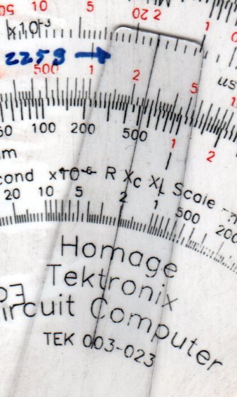
Tek CC – Milled PETG cursor – Lacquer-Stik hairline
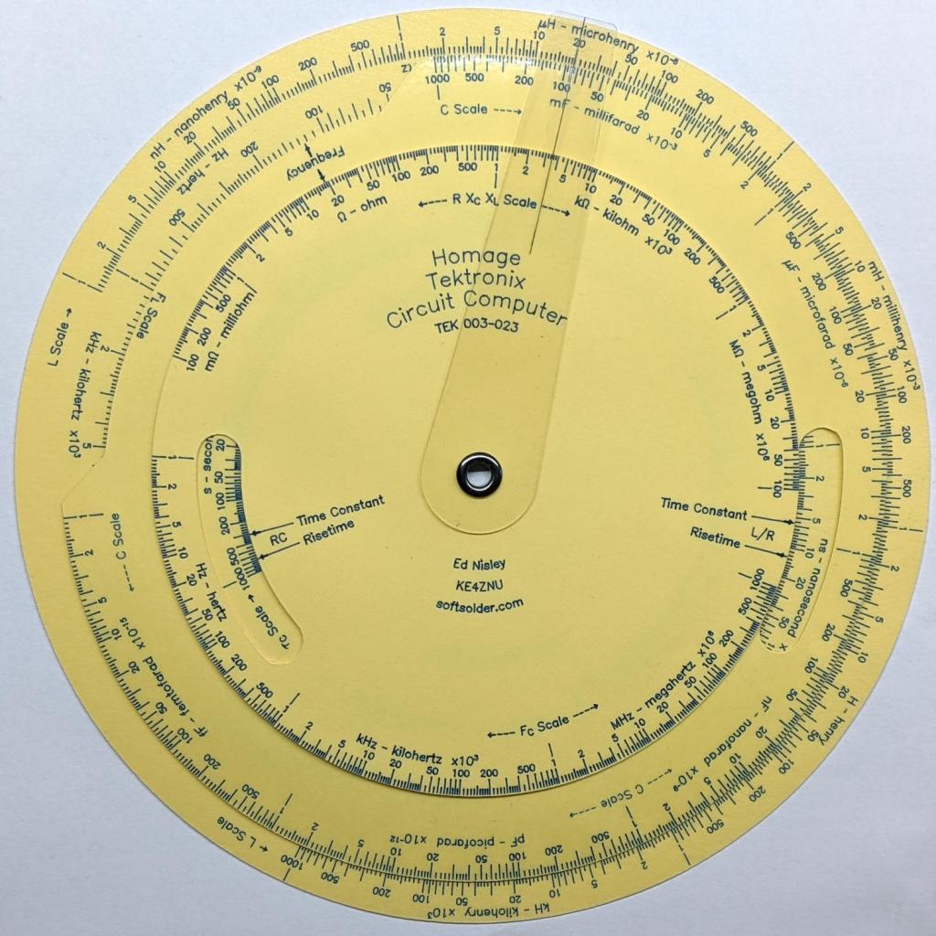
This time, I had the clear film on top!
Although the picture doesn’t do it justice, the scales are in blue ink, which looks better against the yellow background. I suppose I could do custom colors:
Pilot V5RT cartridge – ink levels
The line width has decreased as the ink level drops: 0.3 mm on yellow card stock and 0.2 mm on glossy white brochure paper. I don’t know if they’re supposed to work like that, but, for this application, narrower lines are definitely better.
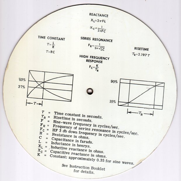
A separate instruction manual told you how to use the thing, under the reasonable assumption you’d be intimately familiar with slide rules.
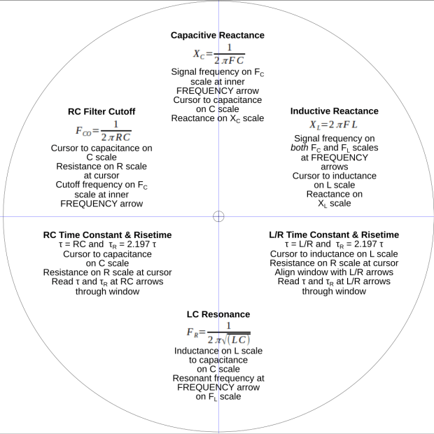
In this day and age, the back should carry how-to-use instructions, so I summarized the manual into half a dozen lists:
Tek CC – instructions – first pass
Which looked fine & dandy & ready to print, thereby exposing various typos / inconsistencies / misalignments:
Tek CC – test print – HP Brochure vs ordinary copy paper
Whereupon I (re)discovered just how much paper matters.
The HP Brochure Glossy inkjet paper on the left produces wonderful results with a 0.5 mm Pilot V5RT ball point pen and has coating on both sides. It’s intended for handouts, brochures, and suchlike; the Pilot pens produce identical results on either side.
The same text, printed on plain old 22 pound “multipurpose” paper on the right, looks much better and makes the HP paper looks like something done with crayon on paper towel.
I could try a font with finer strokes, but … ick.
It’s unclear whether Brochure Matte paper would make any difference, nor whether running coated “inkjet” paper through a laser printer would have an … infelicitous … outcome.
Past experience shows the unsteady ziggurat of Linux printing doesn’t respond well to tweakage: when the default settings don’t work, there’s no easy / predictable way to change any particular setting.
For future reference, print the instruction on what will become the back of the bottom deck, mark the center point, tape it to the CNC 3018 platform, touch off XY = 0 at the center, and draw the front scales: everything lines up perfectly without extra fuss & bother.
Based on manually scratching some acrylic, the GCMC code retraced the hairline four times to help the Sharpie stick to the groove. Maybe fewer passes would be better?
Affix a PETG scrap to the milling fixture for some manual CNC action:
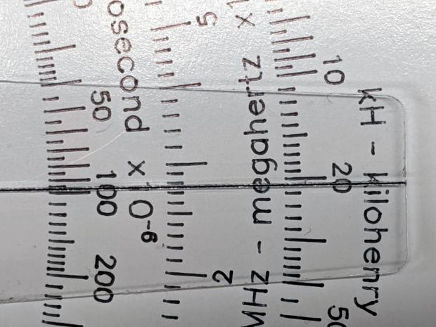
PETG – engrave through film
Just to see what happened, I made the first scratch through the protective film and, because it’s hard to tell which side is up, the scratch went through the white film.
Repeat several times with variations in number of passes & downforce:
The absolute best-looking line is at the top, with the diamond point scribing through the (white) protective plastic film.
Multiple passes average out the waves / glitches / irregularities, at the cost of broadening the hairline.
The bottom hairline suggests a single pass with more downforce produces a broader groove and a finer line of Sharpie ink at the bottom; the top appears more rounded and the bottom more ragged.
Doing one pass with enough pressure to cut through the thinner (?) transparent(-ish) film may produce a better overall result. This will require me to get the orientation right.
The Real Hairline in my K&E Deci-Lon slipstick is a smoothly engraved, neatly half-cylindrical, channel with a smooth thread of red (!) ink / paint / pigment laid along the middle. Obviously, my engraving hand is weak …
The nightmare scenario: engraving a smooth hairline groove, completely backfilling it with paint, sanding (that side of) the cursor smooth to leave the groove’s paint flush with the surface, then polishing the plastic back to full transparency. Even I agree that’s crazy talk, at least for a circular slide rule made with laminated paper decks.
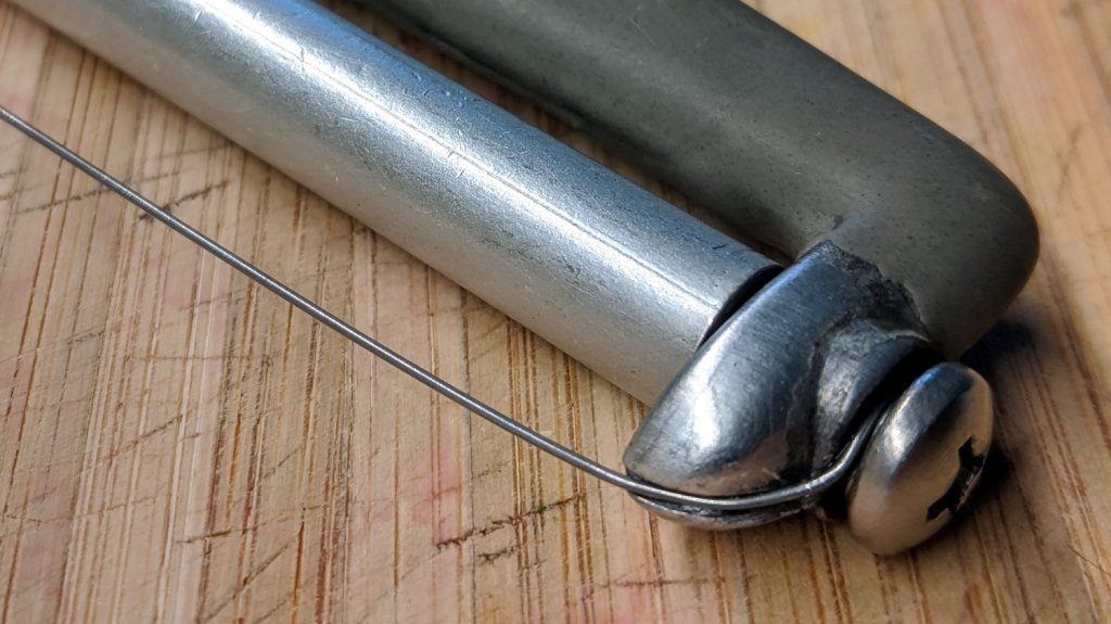
Repairing it with a length of 20 mil = 0.5 mm music wire didn’t take long:
Cheese slicer – new wire
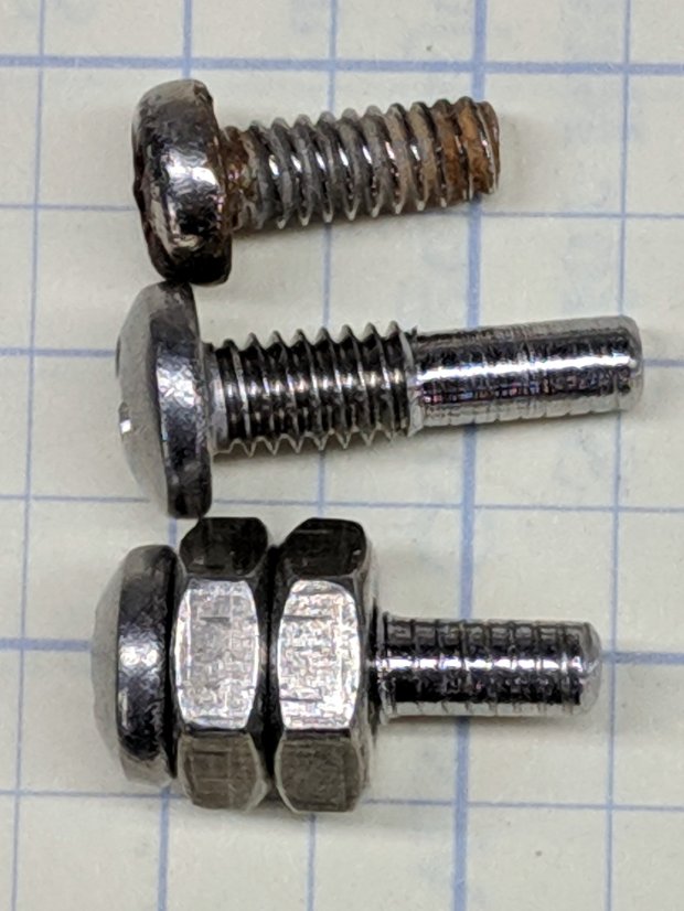
What did take a while was removing one of the screws, turning off another millimeter of thread, and sticking it back in again. The new wire is slightly thinner, stacks up just slightly less under the screw head (maybe I used two turns instead of three?), and let the thread stick into the Delrin bushing I put inside the aluminum roller.
Imagine the middle screw with a slightly longer smooth end and you’ve got the idea:
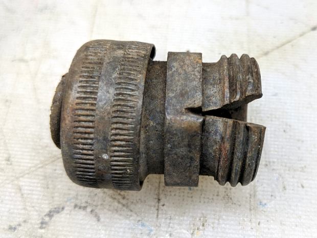
This appeared while we uprooted a row of forsythia along the north border:
Brass hose fitting vs lawnmower
Although FOD has killed a good share of my lawn mowers and blades over the decades, this happened long before my administration and I can’t take credit for the precision targeting.
After removing debris, flattening the top surface, and generally paying more attention to detail, the PETG sheet has much better adhesion to the fixture:
Tek CC – Milled cursor – cleaned fixture
This time, I traced the inside of a drag-knife cut cursor to extract the blank from the stock and, yes, used new double-sided tape under the lower white protective film on the PETG.
Fewer air bubbles means better adhesion:
Tek CC – Milled cursor – fixture adhesion
Spinning the 1/8 inch end mill at about 5000 RPM produced finer swarf at the Sherline’s maximum 609 mm/min = 24 inch/min pace, with less uplift. I suspect Moah RPMs! would be even better, constrained by melting the plastic into heartache & confusion.
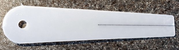
Scribe the hairline with the diamond tool, ease the finished cursor off the fixture, scribble Sharpie into the scratch, and wipe
Tek CC – Milled cursor – second try
It’s Pretty Good™ when seen against an un-laminated bottom deck drawn with a Pilot V5RT pen:
Tek CC – Milled cursor – unlaminated bottom deck
The diamond point tears a slightly gritty path through the PETG, which then looks a bit more granular than a real hairline. I’ve been using four passes for emphasis; perhaps fewer would be better.
The white separating film on the double-sided tape makes the cursor milling fixture look presentable:
Tek CC – Cursor milling fixture – 2-side tape applied
Some deft X-acto knife work exposed the trench around what will be the cursor’s perimeter, in the hope of keeping tape stickiness out of the milling cutter.
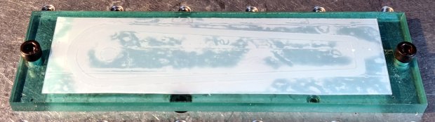
Peeling off the white film and sticking a PETG cursor blank to the tape reveals I didn’t do a particularly good job of cleaning the rubble from the trench edges:
Tek CC – Milled cursor – bad tape application
These PETG sheets arrive with a transparent film on one side and a white film on the other. The picture shows the white film on the bottom of the PETG sheet, with the dark areas corresponding to places where the film sticks to the tape and the tape sticks to the fixture. The lighter areas show an air gap in (at least) one of those interfaces; given the amount of clutter, I think it’s mostly between the tape and the fixture.
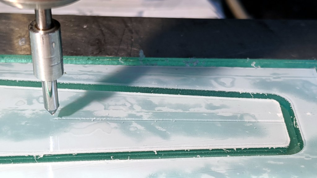
I milled the cursor with a 1/8 inch = 3.175 mm cutter:
Tek CC – Milled cursor – outline
The ball of swarf around the cutter wasn’t as threatening as it appears, because it had very little adhesive holding it together. The rows of swarf surrounding the PETG show why putting the tape all over the fixture isn’t a particularly good idea. ‘Nuff said.
Engraving the hairline with the diamond drag bit was entirely uneventful:
Tek CC – Milled cursor – hairline scribe
Four passes at Z=-2 mm = 300 g downforce put a delicate scratch across the surface. Run a fat black Sharpie along the hairline, wipe off the excess with denatured alcohol, and peel the white film from the other side:
Tek CC – Milled cursor – first try
It’s sitting atop the doodle giving the dimensions, such as they are, for the milling fixture.