The Smell of Molten Projects in the Morning

Ed Nisley's Blog: Shop notes, electronics, firmware, machinery, 3D printing, laser cuttery, and curiosities. Contents: 100% human thinking, 0% AI slop.

Category: Machine Shop

Mechanical widgetry

  • Soaker Hose Clamps

    Soaker Hose Clamps

    Having figured out the geometry for two- and three-channel soaker hoses, I cranked out more clamps:

    Soaker Hose Clamps - production
    Soaker Hose Clamps – production

    Actually, those are the remainder of two production runs devoted to reducing the amount of water sprinkling the garden paths. A 50 foot hose runs along both sides of one 14 foot bed, crosses the path, then continues along the adjacent bed. The hoses have (deliberate!) sprinkler holes along their porous rubber body and sometimes the layout puts a hole where it waters the path.

    The blue silicone rubber strips provide a bit of sealing to prevent the absurdly high pressure water from streaming through the orange PETG clamps. It’s OK if the clamp leaks, but less flow is better!

    I’m getting really good at making those aluminum backing plates and, in fact, I think it’s faster to run the blanks past the disk sander, then drill the holes, than to CNC-machine them. Could be wrong, but Quality Shop Time is not to be sniffed at.

  • Solid Modeling: Support Puzzle

    Solid Modeling: Support Puzzle

    I’ve been putting this type of support structure inside screw holes & suchlike for years:

    Browning Hi-Power Magazine Block - solid model - Generic 1 - support detail
    Browning Hi-Power Magazine Block – solid model – Generic 1 – support detail

    It’s basically a group of small rectangles rotated around the hole’s axis and about one thread thickness shorter than the overhanging interior.

    I’ve found that incorporating exactly the right support structure eliminates Slic3r’s weird growths, eases removal, and generally works better all around.

    So doing this for the baseplate of the Glass Tile frame came naturally:

    Glass Tile Frame - octagonal support
    Glass Tile Frame – octagonal support

    This OpenSCAD snippet plunks one of those asterisks in each of four screw holes:

      if (Support)
        color("Yellow")
          for (i=[-1,1], j=[-1,1])
            translate([i*InsertOC.x/2,j*InsertOC.y/2,0])
              for (a=[0:45:135])
                  rotate(a)
                    translate([0,0,(Screw[LENGTH] - ThreadThick)/2])
                      cube([Screw[OD] - 2*ThreadWidth,2*ThreadWidth,Screw[LENGTH] - ThreadThick],center=true);

    The “cubes” overlap in the middle, with no completely coincident faces or common edges, so it’s 2-manifold. Slic3r, however, produces a weird time estimate whenever the model includes those structures:

    Slic3r - NaN time estimate
    Slic3r – NaN time estimate

    NaN stands for Not A Number and means something horrible has happened in the G-Code generation. Fortunately, the G-Code worked perfectly and produced the desired result, but I’m always uneasy when Something Seems Wrong.

    Messing around with the code produced a slightly different support structure:

    Glass Tile Frame - quad support
    Glass Tile Frame – quad support

    The one thread thick square on the bottom helps glue the structure to the platform and four ribs work just as well as eight in the octagonal hole:

      Fin = [Screw[OD]/2 - 1.5*ThreadWidth,2*ThreadWidth,ScrewRecess - ThreadThick];
      if (Inserts && SupportInserts)
        color("Yellow")
          for (i=[-1,1], j=[-1,1])
            translate([i*InsertOC.x/2,j*InsertOC.y/2,0]) {
              rotate(180/8)
                cylinder(d=6*ThreadWidth,h=ThreadThick,$fn=8);
              for (a=[0:90:360])
                  rotate(a)
                    translate([Fin.x/2 + ThreadWidth/2,0,(ScrewRecess - ThreadThick)/2])
                      cube(Fin,center=true);
            }

    Which changed the NaN time estimates into actual numbers.

    One key difference may be the small hole in the middle. The four ribs (not two!) now overlap by one thread width around the hole, so they’re not quite coincident and Slic3r produces a tidy model:

    Glass Tile Frame - quad support - Slic3r
    Glass Tile Frame – quad support – Slic3r

    The hole eliminates a smear of infill from the center, which may have something to do with the improvement.

    In any event, I have an improved copypasta recipe for the next screw holes in need of support, even if I don’t understand why it’s better.

  • Glass Tiles: Matrix for SK6812 PCBs

    Glass Tiles: Matrix for SK6812 PCBs

    Tweaking the glass tile frame for press-fit SK6812 PCBs in the bottom of the array cells:

    Glass Tile Frame - cell array - openscad
    Glass Tile Frame – cell array – openscad

    Which looks like this with the LEDs and brass inserts installed:

    Glass Tile - 2x2 array - interior
    Glass Tile – 2×2 array – interior

    The base holds an Arduino Nano with room for wiring under the cell array:

    Glass Tile Frame - base - openscad
    Glass Tile Frame – base – openscad

    Which looks like this after it’s all wired up:

    Glass Tile - 2x2 array - wiring
    Glass Tile – 2×2 array – wiring

    The weird colors showing through the inserts are from the LEDs. The red thing in the upper left is a silicone insulation snippet. Yes, that’s hot-melt glue holding the Arduino Nano in place and preventing the PCBs from getting frisky.

    Soak a handful of glass tiles overnight in paint stripper:

    Glass Tiles - paint stripper soak
    Glass Tiles – paint stripper soak

    Whereupon the adhesive slides right off with the gentle application of a razor scraper. Rinse carefully, dry thoroughly, and snap into place.

    Tighten the four M3 SHCS and it’s all good:

    Glass Tile - 2x2 array - operating
    Glass Tile – 2×2 array – operating

    So far, I’ve had two people tell me they don’t know what it is, but they want one:

    Glass Tile - various versions
    Glass Tile – various versions

    The OpenSCAD Customizer lets you set the array size:

    Glass Tile Frame - 3x3 - press-fit SK6812 LEDs
    Glass Tile Frame – 3×3 – press-fit SK6812 LEDs

    However, just because you can do something doesn’t mean you should:

    Glass Tile Frame - 6x6 cell array - openscad
    Glass Tile Frame – 6×6 cell array – openscad

    Something like this might be interesting:

    Glass Tile Frame - 2x6 cell array - openscad
    Glass Tile Frame – 2×6 cell array – openscad

    In round numbers, printing the frame takes about an hour per cell, so a 2×2 array takes three hours and 3×3 array runs around seven hours. A 6×6 frame is just not happening.

    The OpenSCAD source code as a GitHub Gist:

    // Illuminated Tile Grid
    // Ed Nisley – KE4ZNU
    // 2020-05
    /* [Configuration] */
    Layout = "Build"; // [Cell,CellArray,MCU,Base,Show,Build]
    Shape = "Square"; // [Square, Pyramid, Cone]
    Cells = [2,2];
    CellDepth = 15.0;
    Inserts = true;
    SupportInserts = true;
    /* [Hidden] */
    ThreadThick = 0.25;
    ThreadWidth = 0.40;
    HoleWindage = 0.2;
    function IntegerMultiple(Size,Unit) = Unit * ceil(Size / Unit);
    Protrusion = 0.1; // make holes end cleanly
    ID = 0;
    OD = 1;
    LENGTH = 2;
    Tile = [25.0 + 0.1,25.0 + 0.1,4.0];
    WallThick = 4*ThreadWidth;
    FloorThick = 3.0;
    Flange = [2*ThreadWidth,2*ThreadWidth,0]; // ridge supporting tile
    Separator = [3*ThreadWidth,3*ThreadWidth,Tile.z – 1]; // between tiles
    Screw = [3.0,6.0,3.5]; // M3 SHCS, OD=head, LENGTH=head
    Insert = [3.0,4.2,8.0]; // threaded brass insert
    ScrewRecess = Screw[LENGTH] + 4*ThreadThick;
    LEDPCB = [9.6,9.6,2.9]; // round SK6812, squared-off sides
    LED = [5.0 + 2*HoleWindage,5.0 + 2*HoleWindage,1.3];
    LEDOffset = [0.0,0.0,0.0]; // if offset from PCB center
    CellOAL = [Tile.x,Tile.y,0] + Separator + [0,0,CellDepth] + [0,0,FloorThick];
    ArrayOAL = [Cells.x*CellOAL.x,Cells.y*CellOAL.y,CellOAL.z]; // just the LED cells
    BlockOAL = ArrayOAL + [2*WallThick,2*WallThick,0]; // LED cells + exterior wall
    echo(str("Block OAL: ",BlockOAL));
    InsertOC = ArrayOAL – [Insert[OD],Insert[OD],0] – [WallThick,WallThick,0];
    echo(str("Insert OC: ",InsertOC));
    TapeThick = 1.0;
    Arduino = [44.0,18.0,8.0 + TapeThick]; // Arduino Nano to top of USB Mini-B plug
    USBPlug = [15.0,11.0,9.0]; // USB Mini-B plug insulator
    USBOffset = [0,0,5.0]; // offset from PCB base
    WiringSpace = 3.5;
    WiringBay = [(Cells.x – 1)*CellOAL.x + LEDPCB.x,(Cells.y – 1)*CellOAL.y + LEDPCB.x,WiringSpace];
    PlateOAL = [BlockOAL.x,BlockOAL.y,FloorThick + Arduino.z + WiringSpace]; // allow wiring above Arduino
    echo(str("Base Plate: ",PlateOAL));
    echo(str("Screw length: ",(PlateOAL.z – ScrewRecess) + Insert.z/2," to ",(PlateOAL.z – ScrewRecess) + Insert.z));
    LegendRecess = 1*ThreadThick;
    //————————
    module PolyCyl(Dia,Height,ForceSides=0) { // based on nophead's polyholes
    Sides = (ForceSides != 0) ? ForceSides : (ceil(Dia) + 2);
    FixDia = Dia / cos(180/Sides);
    cylinder(d=(FixDia + HoleWindage),h=Height,$fn=Sides);
    }
    //———————–
    // Base and optics in single tile
    module LEDCone() {
    hull() {
    translate([0,0,CellDepth + Tile.z/2])
    cube(Tile – 2*[Flange.x,Flange.y,0],center=true);
    if (Shape == "Square") {
    translate([0,0,LEDPCB.z/2])
    cube([Tile.x,Tile.y,LEDPCB.z] – 2*[Flange.x,Flange.y,0],center=true);
    }
    else if (Shape == "Pyramid") {
    translate([0,0,LEDPCB.z/2])
    cube(LEDPCB,center=true);
    }
    else if (Shape == "Cone") {
    translate([0,0,LEDPCB.z/2])
    cylinder(d=1.0*LEDPCB.x,h=LED.z,center=true);
    }
    else {
    echo(str("Whoopsie! Invalid Shape: ",Shape));
    cube(5);
    }
    }
    }
    // One complete LED cell
    module LEDCell() {
    difference() {
    translate([0,0,CellOAL.z/2])
    cube(CellOAL + [Protrusion,Protrusion,0],center=true); // force overlapping adjacent sides!
    translate([0,0,CellOAL.z – Separator.z + Tile.z/2])
    cube(Tile,center=true);
    translate([0,0,LEDPCB.z])
    LEDCone();
    // cube([LED.x,LED.y,CellOAL.z],center=true);
    translate(-LEDOffset + [0,0,-CellOAL.z/2])
    rotate(180/8)
    PolyCyl(LEDPCB.x,CellOAL.z,8);
    }
    }
    // The whole array of cells
    module CellArray() {
    difference() {
    union() {
    translate([CellOAL.x/2 – Cells.x*CellOAL.x/2,CellOAL.y/2 – Cells.y*CellOAL.y/2,0])
    for (i=[0:Cells.x – 1], j=[0:Cells.y – 1])
    translate([i*CellOAL.x,j*CellOAL.y,0])
    LEDCell();
    if (Inserts) // bosses
    for (i=[-1,1], j=[-1,1])
    translate([i*InsertOC.x/2,j*InsertOC.y/2,0])
    rotate(180/8)
    cylinder(d=Insert[OD] + 2*WallThick,h=Insert[LENGTH],$fn=8);
    }
    if (Inserts) // holes
    for (i=[-1,1], j=[-1,1])
    translate([i*InsertOC.x/2,j*InsertOC.y/2,-Protrusion])
    rotate(180/8)
    PolyCyl(Insert[OD],Insert[LENGTH] + FloorThick + Protrusion,8);
    }
    difference() {
    translate([0,0,CellOAL.z/2])
    cube(BlockOAL,center=true);
    translate([0,0,CellOAL.z])
    cube(ArrayOAL + [0,0,2*CellOAL.z],center=true);
    }
    }
    // Arduino bounding box
    // Origin at center bottom of PCB
    module Controller() {
    union() {
    translate([0,0,Arduino.z/2])
    cube(Arduino,center=true);
    translate([Arduino.x/2 – Protrusion,-USBPlug.y/2,USBOffset.z + TapeThick – USBPlug.z/2])
    cube(USBPlug + [Protrusion,0,0],center=false);
    }
    }
    // Baseplate
    module BasePlate() {
    difference() {
    translate([0,0,PlateOAL.z/2])
    cube(PlateOAL,center=true);
    translate([PlateOAL.x/2 – Arduino.x/2 – 2*WallThick,0,FloorThick])
    Controller();
    translate([PlateOAL.x/2 – Arduino.x/2 – 2*WallThick,0,FloorThick + PlateOAL.z/2])
    cube([Arduino.x – 2*2.0,WiringBay.y,PlateOAL.z],center=true); // cutouts beside MCU
    translate([0,0,PlateOAL.z – WiringBay.z + PlateOAL.z/2 – Protrusion])
    cube([PlateOAL.x – 2*WallThick,WiringBay.y,PlateOAL.z],center=true); // cutout above MCU
    translate([0,0,PlateOAL.z – WiringBay.z + PlateOAL.z/2 – Protrusion])
    cube([WiringBay.x,PlateOAL.y – 2*WallThick,PlateOAL.z],center=true); // cutout above MCU
    if (Inserts)
    for (i=[-1,1], j=[-1,1])
    translate([i*InsertOC.x/2,j*InsertOC.y/2,-Protrusion])
    rotate(180/8) {
    PolyCyl(Screw[ID],2*PlateOAL.z,8);
    PolyCyl(Screw[OD],ScrewRecess + Protrusion,8);
    }
    cube([45,17.0,2*LegendRecess],center=true);
    }
    linear_extrude(height=2*LegendRecess) {
    translate([0,1])
    rotate(-0*90) mirror([1,0,0])
    text(text="Ed Nisley",size=6,font="Arial:style:Bold",halign="center");
    translate([0,-6.5])
    rotate(-0*90) mirror([1,0,0])
    text(text="softsolder.com",size=4.5,font="Arial:style:Bold",halign="center");
    }
    Fin = [Screw[OD]/2 – 1.5*ThreadWidth,2*ThreadWidth,ScrewRecess – ThreadThick];
    if (Inserts && SupportInserts)
    color("Yellow")
    for (i=[-1,1], j=[-1,1])
    translate([i*InsertOC.x/2,j*InsertOC.y/2,0]) {
    rotate(180/8)
    cylinder(d=6*ThreadWidth,h=ThreadThick,$fn=8);
    for (a=[0:90:360])
    rotate(a)
    translate([Fin.x/2 + ThreadWidth/2,0,(ScrewRecess – ThreadThick)/2])
    cube(Fin,center=true);
    }
    }
    //———————–
    // Build things
    if (Layout == "Cell")
    LEDCell();
    else if (Layout == "CellArray")
    CellArray();
    else if (Layout == "MCU")
    Controller();
    else if (Layout == "Base")
    BasePlate();
    else if (Layout == "Show") {
    translate([0,0,3*PlateOAL.z])
    CellArray();
    BasePlate();
    translate([PlateOAL.x/2 – Arduino.x/2 – 2*WallThick,0,FloorThick])
    color("Orange",0.3)
    Controller();
    }
    else if (Layout == "Build") union() {
    translate([0,0.6*BlockOAL.y,0])
    CellArray();
    translate([0,-0.6*BlockOAL.x,0])
    rotate(90)
    BasePlate();
    }

  • Screw Thread Measurement

    Screw Thread Measurement

    While I was cutting threads for the Floor Lamp poles, I tried measuring my progress over wires:

    Floor Lamp - tube fitting - thread measurement
    Floor Lamp – tube fitting – thread measurement

    Those are three lengths of music wire, slightly bent from their storage roll, held in place with a precision clamp metric micrometer. Given the crudity of the setup, the uncalibrated wire diameter, and my lack of thread-fu, the results came out both close and unconvincing.

    A set of real thread measuring wires being cheap & readily available, I’m prepared for the next time around this block:

    Thread Measuring Wires - eBay set
    Thread Measuring Wires – eBay set

    The 185 mil “wires” (they’re all allegedly ground rod) will let me cut threads matching things like a Jesus nut; they’re suited for 3 TPI / 8 mm pitch screws. Mostly, wires from the front row will be all I ever need.

    Which look like this in action:

    Thread Measuring Wires - eBay setThread Measuring Wires - detail
    Thread Measuring Wires – eBay setThread Measuring Wires – detail

    The black doodad (the set includes half a dozen for all the wire sizes) fits over the micrometer anvil and holds two wires betwixt anvil and screw, leaving me to manipulate the screw, the third wire, and the micrometer with my remaining hands. Hence the vise holding the micrometer, which is known to be Very Bad Practice.

    From the side:

    Thread Measuring Wires - overview
    Thread Measuring Wires – overview

    All of the smaller wires measure 0.5 mil too thin, which is likely due to my lack of calibrated measurement equipment:

    Thread Measuring Wires - scant 24 mil
    Thread Measuring Wires – scant 24 mil

    The few thread pitch diameters I measured also came out slightly too small, again likely due to calibration and screw tolerances.

    The LittleMachineShop description of measuring threads over wires seems entirely adequate.

    To forestall link rot, a slightly rearranged version of their tables of wire constants:

    Thread Wire Measurement Constants
    Thread Wire Measurement Constants

    The lower table has metric thread pitches with the wire sizes in inches.

    You measure the distance over the recommended wire (in inches or millimeters, as appropriate), subtract the constant, and get the pitch diameter in the same units. Conversely, add the constant to the desired pitch diameter to get the target over-wire distance, carefully cut the thread until it measures a bit less than that, back up sixty seconds, and cut it spot on.

    Verily, it is written: there is no UnDo key (⎌) in machine shop work.

  • Garden Hose Valve Wrench: Reinforced

    Garden Hose Valve Wrench: Reinforced

    After five gardening seasons, my simple 3D printed wrench broke:

    Hose Valve Knob - fractured
    Hose Valve Knob – fractured

    Although Jason’s comment suggesting carbon-fiber reinforcing rods didn’t prompt me to lay in a stock, ordinary music wire should serve the same purpose:

    Hose Valve Knob - cut pins
    Hose Valve Knob – cut pins

    The pins are 1.6 mm diameter and 20 mm long, chopped off with hardened diagonal cutters. Next time, I must (remember to) grind the ends flat.

    The solid model needs holes in appropriate spots:

    Hose Valve Knob - Reinforced - Slic3r
    Hose Valve Knob – Reinforced – Slic3r

    Yes, I’m going to put round pins in square holes, without drilling the holes to the proper diameter: no epoxy, no adhesive, just 20 mm of pure friction.

    The drill press aligns the pins:

    Hose Valve Knob - pin ready
    Hose Valve Knob – pin ready

    And rams them about halfway down:

    Hose Valve Knob - pin midway
    Hose Valve Knob – pin midway

    Close the chuck jaws and shove them flush with the surface:

    Hose Valve Knob - pins installed
    Hose Valve Knob – pins installed

    You can see the pins and their solid plastic shells through the wrench stem:

    Hose Valve Knob - assembled
    Hose Valve Knob – assembled

    Early testing shows the reinforced wrench works just as well as the previous version, even on some new valves sporting different handles, with an equally sloppy fit for all. No surprise: I just poked holes in the existing model and left all the other dimensions alone.

    The OpenSCAD source code as a GitHub Gist:

    // Hose connector knob
    // Ed Nisley KE4ZNU – June 2015
    // 2020-05 add reinforcing rods
    Layout = "Build"; // [Knob, Stem, Show, Build]
    RodHoles = true;
    //- Extrusion parameters – must match reality!
    /* [Hidden] */
    ThreadThick = 0.25;
    ThreadWidth = 0.40;
    function IntegerMultiple(Size,Unit) = Unit * ceil(Size / Unit);
    Protrusion = 0.1;
    HoleWindage = 0.2;
    //——
    // Dimensions
    /* [Dimensions] */
    RodOD = 1.6;
    RodAngle = 35;
    /* [Hidden] */
    StemOD = 30.0; // max OD for valve-to-valve clearance
    BossOD = 16.0; // single-ended handle boss
    SlotWidth = 13.0;
    SlotHeight = 10.0;
    StemInset = 10.0;
    StemLength = StemInset + SlotHeight + 25.0;
    StemSides = 2*4;
    Align = 0*180/StemSides; // 1* produces thinner jaw ends
    KnobOD1 = 70; // maximum dia without chamfer
    KnobOD2 = 60; // top dia
    KnobSides = 4*4;
    DomeHeight = 12; // dome shape above lobes
    KnobHeight = DomeHeight + 2*SlotHeight;
    DomeOD = KnobOD2 + (KnobOD1 – KnobOD2)*(DomeHeight/KnobHeight);
    DomeArcRad = (pow(KnobHeight,2) + pow(DomeOD,2)/4) / (2*DomeHeight);
    RodBCD = (StemOD + BossOD)/2;
    //- Adjust hole diameter to make the size come out right
    module PolyCyl(Dia,Height,ForceSides=0) { // based on nophead's polyholes
    Sides = (ForceSides != 0) ? ForceSides : (ceil(Dia) + 2);
    FixDia = Dia / cos(180/Sides);
    cylinder(r=(FixDia + HoleWindage)/2,h=Height,$fn=Sides);
    }
    //– Stem for valve handles
    module Stem() {
    difference() {
    rotate(Align)
    cylinder(d=StemOD,h=StemLength,$fn=StemSides);
    translate([0,0,SlotHeight/2 – Protrusion/2])
    cube([2*StemOD,SlotWidth,(SlotHeight + Protrusion)],center=true);
    translate([0,0,-Protrusion])
    cylinder(d=BossOD,h=SlotHeight,$fn=2*StemSides);
    if (RodHoles)
    for (i=[-1:1])
    rotate(i*RodAngle + 90)
    for (j=[-1,1])
    translate([j*RodBCD/2,0,-Protrusion])
    rotate(180/4)
    PolyCyl(RodOD,2*SlotHeight,4);
    }
    }
    //– Hand-friendly knob
    module KnobCap() {
    difference() {
    scale([1.0,0.75,1.0])
    rotate(180/KnobSides)
    intersection() {
    translate([0,0,(KnobHeight-DomeArcRad)])
    sphere(r=DomeArcRad,$fa=180/KnobSides);
    cylinder(r1=KnobOD1/2,r2=KnobOD2/2,h=KnobHeight,$fn=KnobSides);
    cylinder(r1=KnobOD2/2,r2=KnobOD1/2,h=KnobHeight,$fn=KnobSides);
    }
    translate([0,0,-Protrusion])
    rotate(Align)
    cylinder(d=(StemOD + 2*ThreadWidth),h=(StemInset + Protrusion),$fn=StemSides);
    }
    }
    //- Build it
    if (Layout == "Knob")
    KnobCap();
    if (Layout == "Stem")
    Stem();
    if (Layout == "Build") {
    translate([-KnobOD1/2,0,0])
    KnobCap();
    translate([StemOD/2,0,StemLength])
    rotate([180,0,0])
    Stem();
    }
    if (Layout == "Show") {
    translate([0,0,0])
    Stem();
    translate([0,0,StemLength – StemInset])
    KnobCap();
    }

  • Soaker Hose End Plug

    Soaker Hose End Plug

    One of the soaker hoses in Mary’s Vassar Farms garden split lengthwise near one end:

    Soaker Hose Plug - hose split
    Soaker Hose Plug – hose split

    Although the hose is fully depreciated, I thought it’d be worthwhile to cut off the damaged end and conjure an end cap to see if a simple plug can withstand 100 psi water pressure.

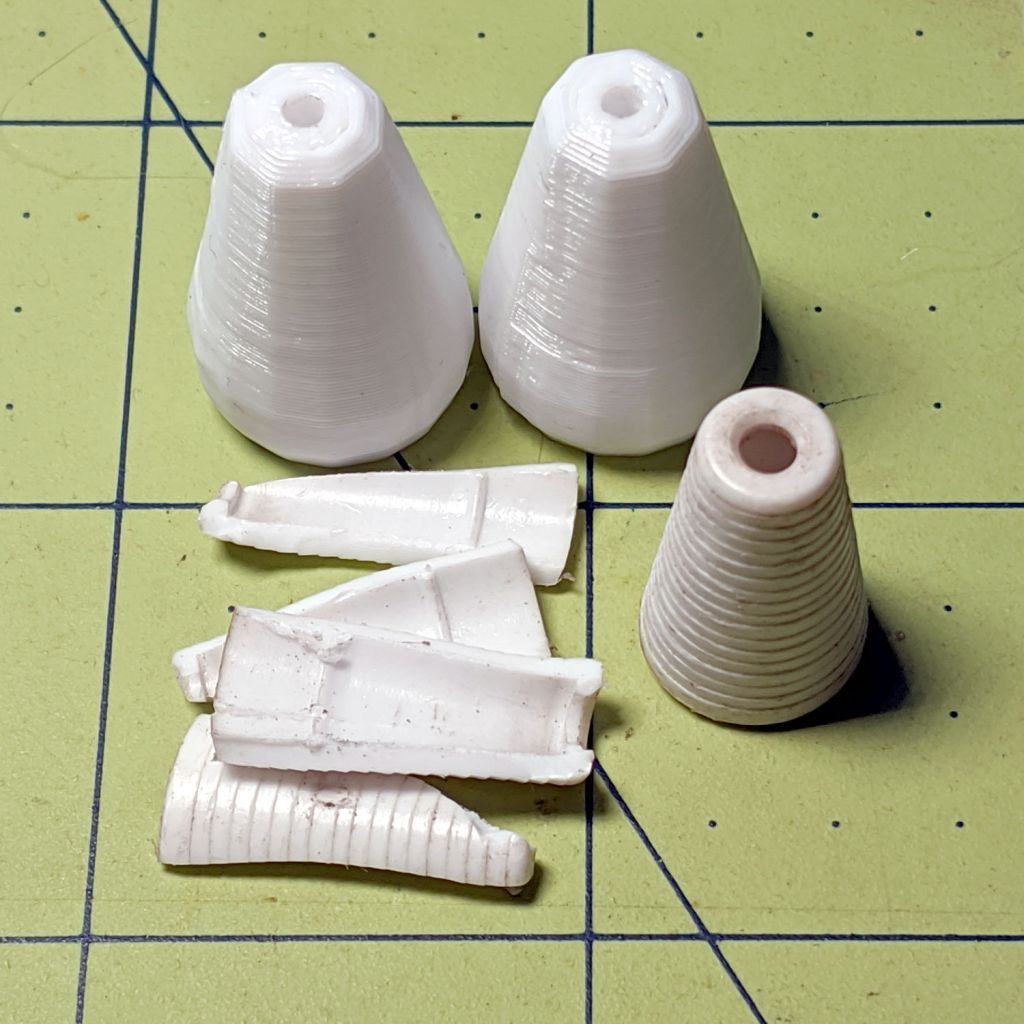
    A pair of Delrin (because I have it) plugs with serrations fill the hose channels, with the outer clamp squishing the hose against them:

    Soaker Hose Plug - channel plugs - side view
    Soaker Hose Plug – channel plugs – side view

    In real life, they’ll be pushed completely into the hose, with a generous layer of silicone snot caulk improving their griptivity.

    I started with 8 mm plugs, but they didn’t quite fill the channels:

    Soaker Hose Plug - channel plugs - 8 mm test fit
    Soaker Hose Plug – channel plugs – 8 mm test fit

    Going to 8.5 mm worked better, although there’s really no way to force the granulated rubber shape into a snug fit around a cylinder:

    Soaker Hose Plug - channel plugs test fit
    Soaker Hose Plug – channel plugs test fit

    Fortunately, they need not be leakproof, because leaking is what the hose does for a living. Well, did for a living, back before it died.

    The clamps have a solid endstop, although it’s more to tidy the end than to hold the plugs in place:

    Soaker Hose End Plug - Slic3r
    Soaker Hose End Plug – Slic3r

    The clamps need aluminum backing plates to distribute the stress evenly across their flat sides:

    Soaker Hose Plug - installed
    Soaker Hose Plug – installed

    Those are 8-32 stainless steel screws. The standard 1 inch length worked out exactly right through no fault of my own.

    The OpenSCAD source code as a GitHub Gist:

    // Rubber Soaker Hose End Plug
    // Ed Nisley KE4ZNU June 2019
    // 2020-05 Two-channel hose end plug
    Layout = "Hose"; // [Hose,Block,Show,Build]
    //- Extrusion parameters must match reality!
    /* [Hidden] */
    ThreadThick = 0.25;
    ThreadWidth = 0.40;
    HoleWindage = 0.2;
    Protrusion = 0.1; // make holes end cleanly
    inch = 25.4;
    function IntegerMultiple(Size,Unit) = Unit * ceil(Size / Unit);
    //———-
    // Dimensions
    // Hose lies along X axis
    HoseTubeOD = 12.0; // water tube diameter
    HoseTubeOC = 12.5; // .. spacing
    HoseWebThick = 7.8; // center joining tubes
    Hose = [100,25.0,HoseTubeOD]; // X=very long, Y=overall width, Z=thickness
    HoseSides = 12*4;
    PlugLength = 25.0; // plugs in hose channels
    PlateThick = 5.0; // end block thickness
    WallThick = 2.0; // overall minimum thickness
    Kerf = 0.75; // cut through middle to apply compression
    ID = 0;
    OD = 1;
    LENGTH = 2;
    // 8-32 stainless screws
    Screw = [4.1,8.0,3.0]; // OD = head LENGTH = head thickness
    Washer = [4.4,9.5,1.0];
    Nut = [4.1,9.7,6.0];
    CornerRadius = Washer[OD]/2;
    ScrewOC = Hose.y + Washer[OD];
    echo(str("Screw OC: ",ScrewOC));
    BlockOAL = [PlugLength + PlateThick,ScrewOC + Washer[OD],2*WallThick + Hose.z]; // overall splice block size
    echo(str("Block: ",BlockOAL));
    //———————-
    // Useful routines
    module PolyCyl(Dia,Height,ForceSides=0) { // based on nophead's polyholes
    Sides = (ForceSides != 0) ? ForceSides : (ceil(Dia) + 2);
    FixDia = Dia / cos(180/Sides);
    cylinder(d=(FixDia + HoleWindage),h=Height,$fn=Sides);
    }
    // Hose shape
    module HoseProfile() {
    rotate([0,-90,0])
    translate([0,0,-Hose.x/2])
    linear_extrude(height=Hose.x,convexity=4)
    union() {
    for (j=[-1,1]) // outer channels
    translate([0,j*HoseTubeOC/2])
    circle(d=HoseTubeOD,$fn=HoseSides);
    translate([0,0])
    square([HoseWebThick,HoseTubeOC],center=true);
    }
    }
    // Outside shape of splice Block
    // Z centered on hose rim circles, not overall thickness through center ridge
    module SpliceBlock() {
    difference() {
    hull()
    for (i=[-1,1], j=[-1,1]) // rounded block
    translate([i*(BlockOAL.x/2 – CornerRadius),j*(BlockOAL.y/2 – CornerRadius),-BlockOAL.z/2])
    cylinder(r=CornerRadius,h=BlockOAL.z,$fn=4*8);
    for (j=[-1,1]) // screw holes
    translate([0,
    j*ScrewOC/2,
    -(BlockOAL.z/2 + Protrusion)])
    PolyCyl(Screw[ID],BlockOAL.z + 2*Protrusion,6);
    cube([2*BlockOAL.x,2*BlockOAL.y,Kerf],center=true); // slice through center
    }
    }
    // Splice block less hose
    module ShapedBlock() {
    difference() {
    SpliceBlock();
    translate([(-Hose.x/2) + (BlockOAL.x/2) – PlateThick,0,0])
    HoseProfile();
    }
    }
    //———-
    // Build them
    if (Layout == "Hose")
    HoseProfile();
    if (Layout == "Block")
    SpliceBlock();
    if (Layout == "Show") {
    ShapedBlock();
    translate([(-Hose.x/2) + (BlockOAL.x/2) – PlateThick,0,0])
    color("Green",0.25)
    HoseProfile();
    }
    if (Layout == "Build") {
    SliceOffset = 0;
    intersection() {
    translate([SliceOffset,0,BlockOAL.z/4])
    cube([4*BlockOAL.x,4*BlockOAL.y,BlockOAL.z/2],center=true);
    union() {
    translate([0,0.6*BlockOAL.y,BlockOAL.z/2])
    ShapedBlock();
    translate([0,-0.6*BlockOAL.y,BlockOAL.z/2])
    rotate([0,180,0])
    ShapedBlock();
    }
    }
    }

    The original doodle, with dimensions vaguely related to the final model:

    Soaker Hose End Plug - hose dimensions
    Soaker Hose End Plug – hose dimensions

    There is, as far as I can tell, no standardization of dimensions or shapes across manufacturers, apart from the threaded hose fittings.

  • Kenmore 158 Sewing Machine: More Deglaring

    Kenmore 158 Sewing Machine: More Deglaring

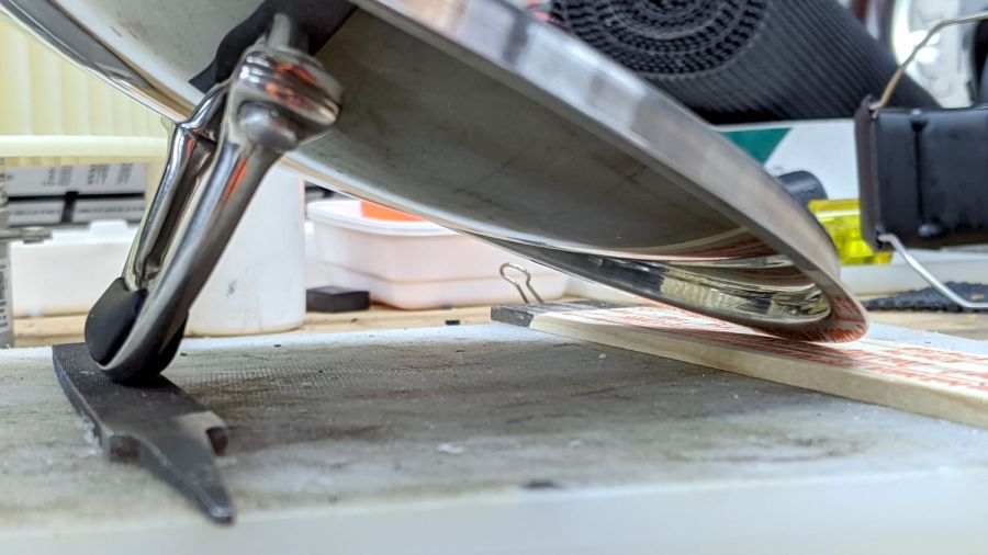
    My first pass at deglaring the shiny metal parts on Mary’s brightly lit Kenmore 158 used translucent mailing labels on the “hand hole cover” in front of the needle:

    Kenmore 158 - non-glare cover plate
    Kenmore 158 – non-glare cover plate

    That worked surprisingly well for surprisingly long, but the edges eventually came loose and, after far too long, I deployed the Tiny Sandblaster™:

    Kenmore 158 - matte cover plate - feet
    Kenmore 158 – matte cover plate – feet

    The mottled matte effect isn’t quite what I expected, but it’s better-looking in person and we deemed it Good Enough™ for the purpose.

    You saw the foot on the left in the previous effort:

    Kenmore 158 - matte cover plate - feet - detail
    Kenmore 158 – matte cover plate – feet – detail

    The rounded plate directly under the needle sits far enough back to not reflect any of the LEDs toward her normal operating position, so we decided it didn’t need sandblasting.

    She now has plenty of light where she needs it, with no glare from the metal bits.