So another knockoff Neopixel started flickering and its blue LED went dark:
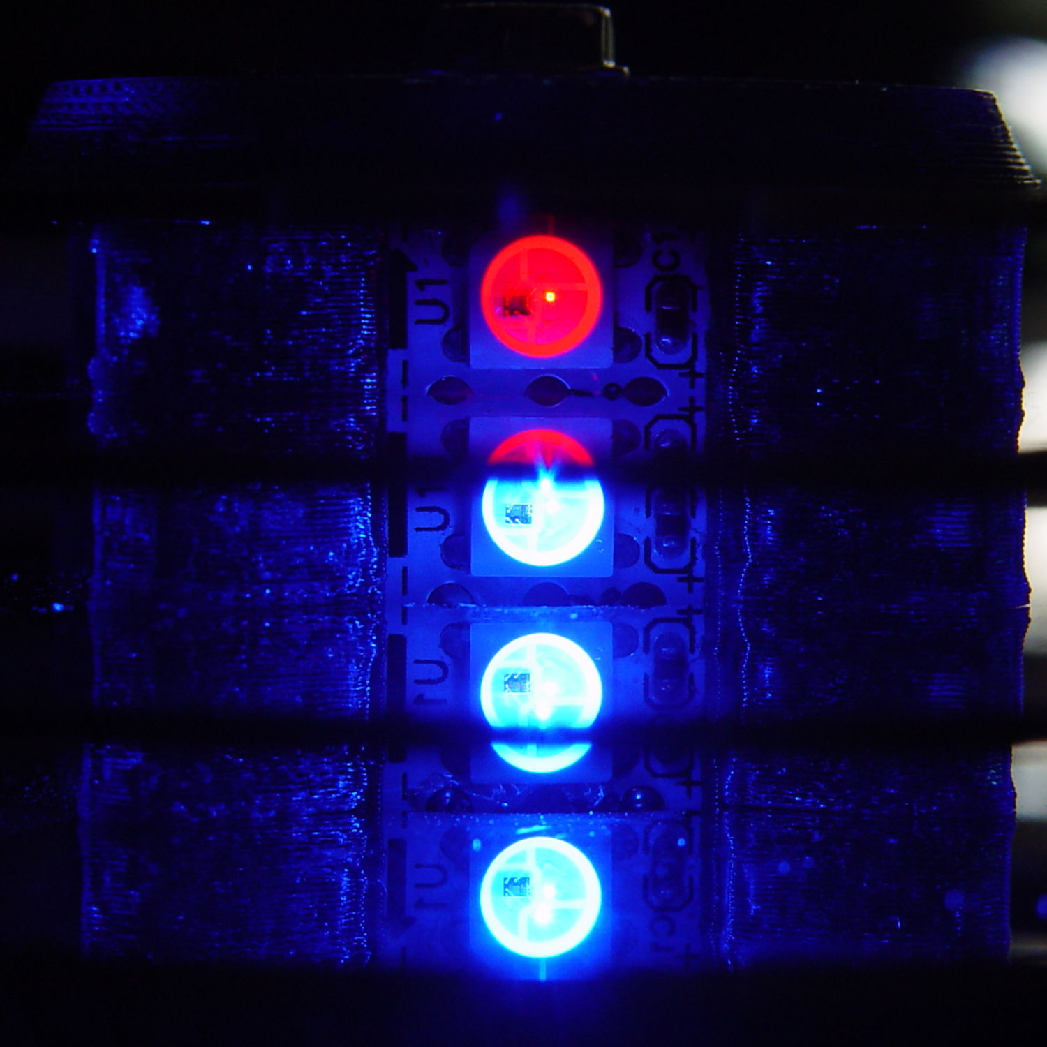
Squirting it with circuit cooler brought it back to life, albeit briefly, so it’s a real thermal failure. OK, after I get smacked upside the head twice, I can recognize a problem when I see it.
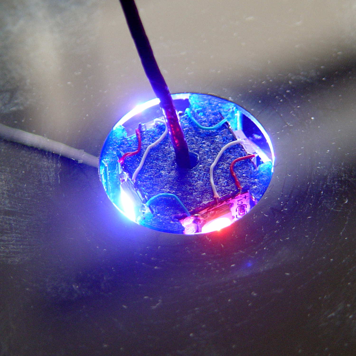
I removed the top cover and jammed a themocouple into the screw hole in the middle of the pillar:
A folded tissue weighted down with random desktop junk kept the breeze out of the interior:
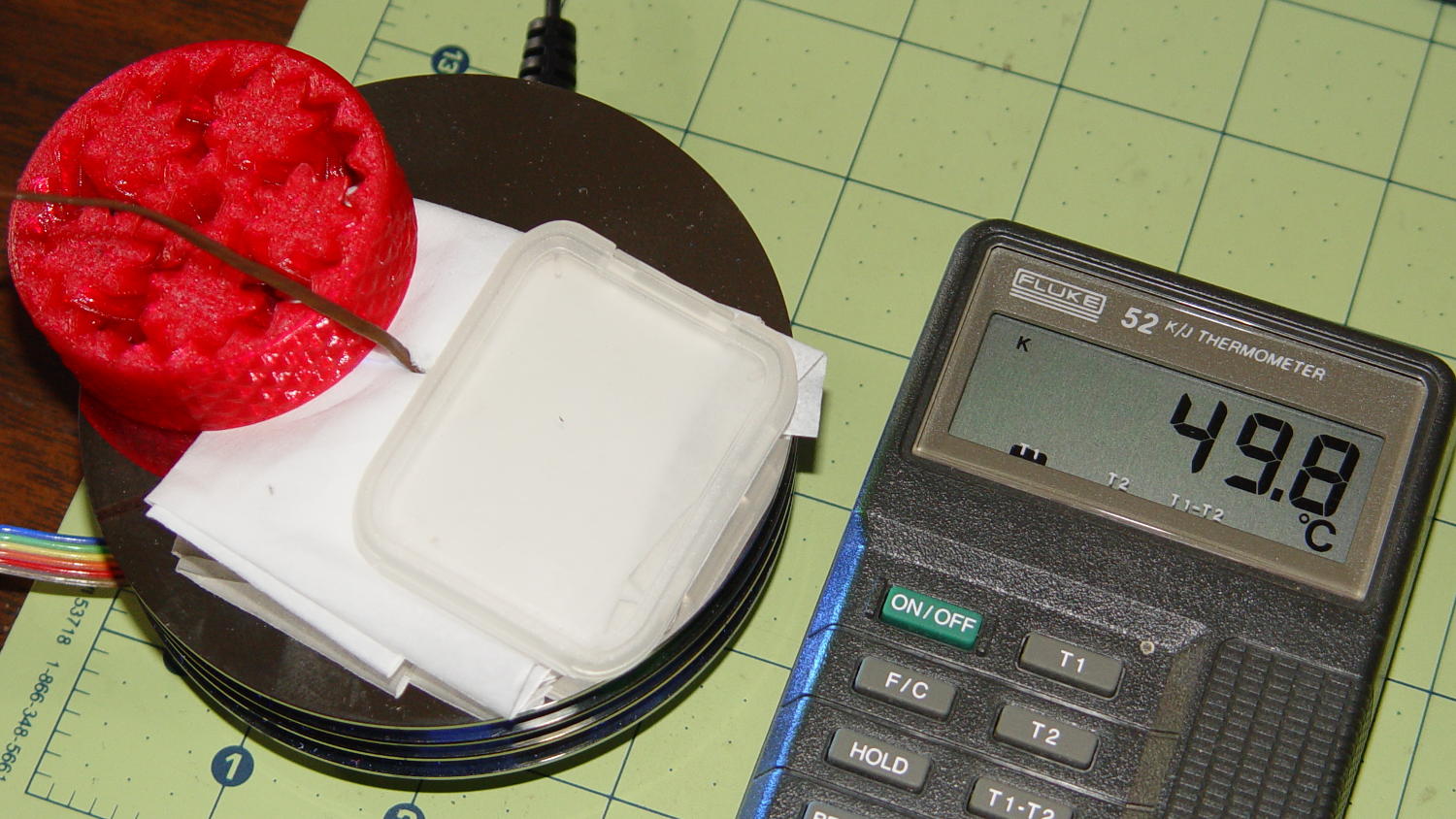
If the middle of the column hits 50 °C, what’s it like inside the 5050 packages with all those LEDs blazing away? Looks like I’ve been cooking those poor knockoff Neopixels to death.
The temperature is 50 °C with the LEDs running at maximum PWM = 128. Reducing the maximum PWM to 64 reduces the core to 30 °C and that dead blue LED springs back to life.
Figuring each LED package dissipate 250-ish mW at full throttle, that’s 120 mW at PWM 128 / 60 mW at PWM 64. The set of 12 packages dissipates 1.4 W / 750 mW, so, in a 22 °C room, the thermal coefficient is up around 10 to 20 °C/W, which is somewhere between bad and awful. Running the LEDs at full throttle obviously isn’t an option and even half-throttle really doesn’t work.
So, OK, mounting LED strips on a clever 3D printed plastic column with zero air circulation isn’t nearly as smart an idea as I thought: barely more than a watt burns right through the redline.
The Neopixel specs have nothing to say about the thermal coefficient from the LED junctions to the package leads, but cooling the copper conductors in the flex PCB can’t possibly hurt.
No, I do not want to CNC machine an aluminum pillar with little tabs on the platter for better heatsinking. It would be an interesting design project, though.

Comments
12 responses to “Hard Drive Platter Mood Light: Thermal (Mis)Management”
Do you want to 3-D print a hollow pillar with vent holes out the protrusions and even grazing across the back sides of the PCB strips, and screw a tiny tiny fan to the top, to see whether some air movement is enough to keep the LEDs alive?
I briefly considered modeling channels for brass strips epoxied to the top or bottom platter, similar strips wrapping sideways into the spacers, making a mold to cast the pillar in metal-filled epoxy, or doing a full-on Sherline CNC project with the rotary table.
But, by and large, methinks I have a message from the universe telling me that the Mood Light was a clever idea, that it looks great, and to always remember that pride goes before destruction… [grin]
The other approach is to tweak the software so that only a few LEDs are on at a time, and vary which ones. The total brightness (and therefore heat) would go down, but you’d still have some bright(ish) LEDs winking at you.
When I showed it off to our Larval Engineer, she liked the lamp test sequence best: high-power white beams FTW! After a cold start, each one was on for a few seconds and didn’t overheat, although after the pillar got up to running temperature, that LED failed as described.
So, with a slight firmware mod to emphasize flashing, maybe the thing has a future as a party decoration…
Those platters are an attractive way to dissipate heat. I wonder if some creatively cut and folded Z brackets would be sufficient to bring heat from the back of the LED strips to the nearest platters. Wouldn’t look as nice, and still a tricky design problem (a metal punch and bending brake are handy for thicker ones, but maybe even some thin sheet metal would help).
I have the uneasy feeling that I must try something like that, just to see how it performs. Forcing metal-filled epoxy into molded channels behind the LEDs might actually work… drat!
You could also add a small pancake motor from in the bottom to spin the platters, print the vanes to add to the outer edge and you’d get a turbine cooler – disco lights – persistence of vision animation hybrid gizmo :)
The Neopixel datasheet was instructive, but frustrating. Nothing shows attention to detail like specifying the maximum junction temp with no way of estimating that temp. A dark-alley conversation with the development/marketing team would fill my fantasies…
However, if a silicon diode is accessible (probably a protection diode on the input or output), it could be measured. On a bipolar part, you had the substrate diode, but you had to reverse polarity to measure it. If there’s a clamp diode (might be junction or a schottky), it’s easier, (kinda, see note) since the clamp should be referenced to Vdd.
As a reminder, the algorithm is as such:
1) measure the diode at a fixed current with the part cold. Note the temperature that the part sees.
2) Power up the part (use an operating mode that can be repeated) long enough for it to settle. Measure the stress power at this point (it can change as it warms up). If the package temperature is forced, a few seconds would work.
3) After that stress period, quickly measure the diode voltage at that same current.
3.1) if it’s a junction diode (0.7 V at 1mA or so), use 2mV/degree C). If it’s a Schottky, the value will have to be determined
by doing initial measurements at a couple of known temperatures. The Vf(temp) is still linear.
4) Do the rest of the math and you have the temp rise for a known value of power. Apply accordingly.
The first time this came up, one of the instrumentation guys did a box, using TTL, opamps and thumbwheels. Years later, I did a similar job on automatic test equipment. If it’s a clamp diode, I’d think it’d be semi-easy using an Arduino to do a lot of the work.
On the platters as heatsinks, maybe a design with the discs vertical, and goober the neopixels to them with heat sink compound. (Memory flashback of an old jukebox.)
I like Thomas Edison’s approach: you now know at one way that doesn’t work.
Vertical platters would look disturbingly like a meat slicer…
[…] the Mood Light’s dozen Neopixels jammed into the platter’s hub ring, running one Neopixel at full throttle […]
[…] Shot of circuit cooler: fail […]