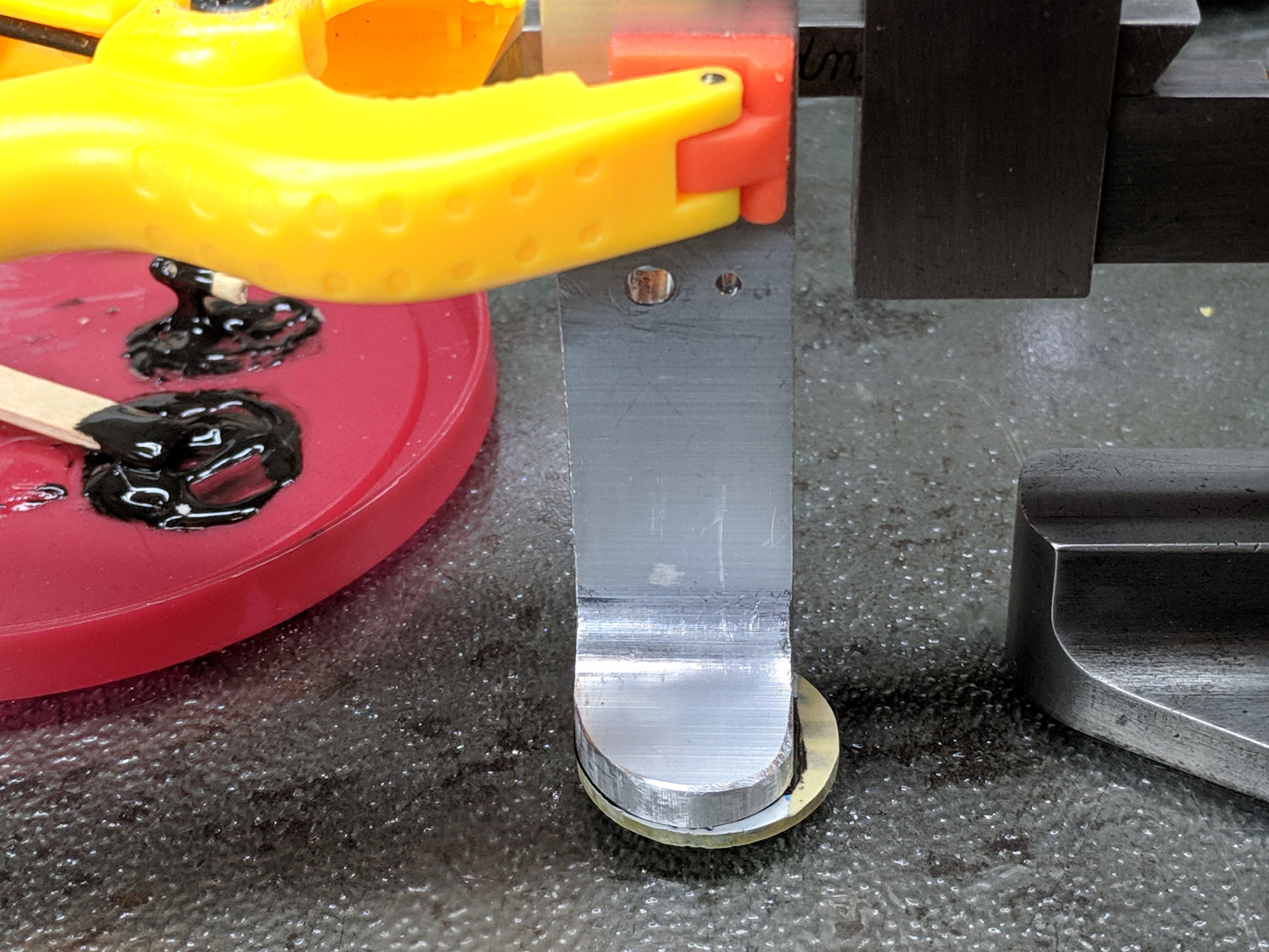
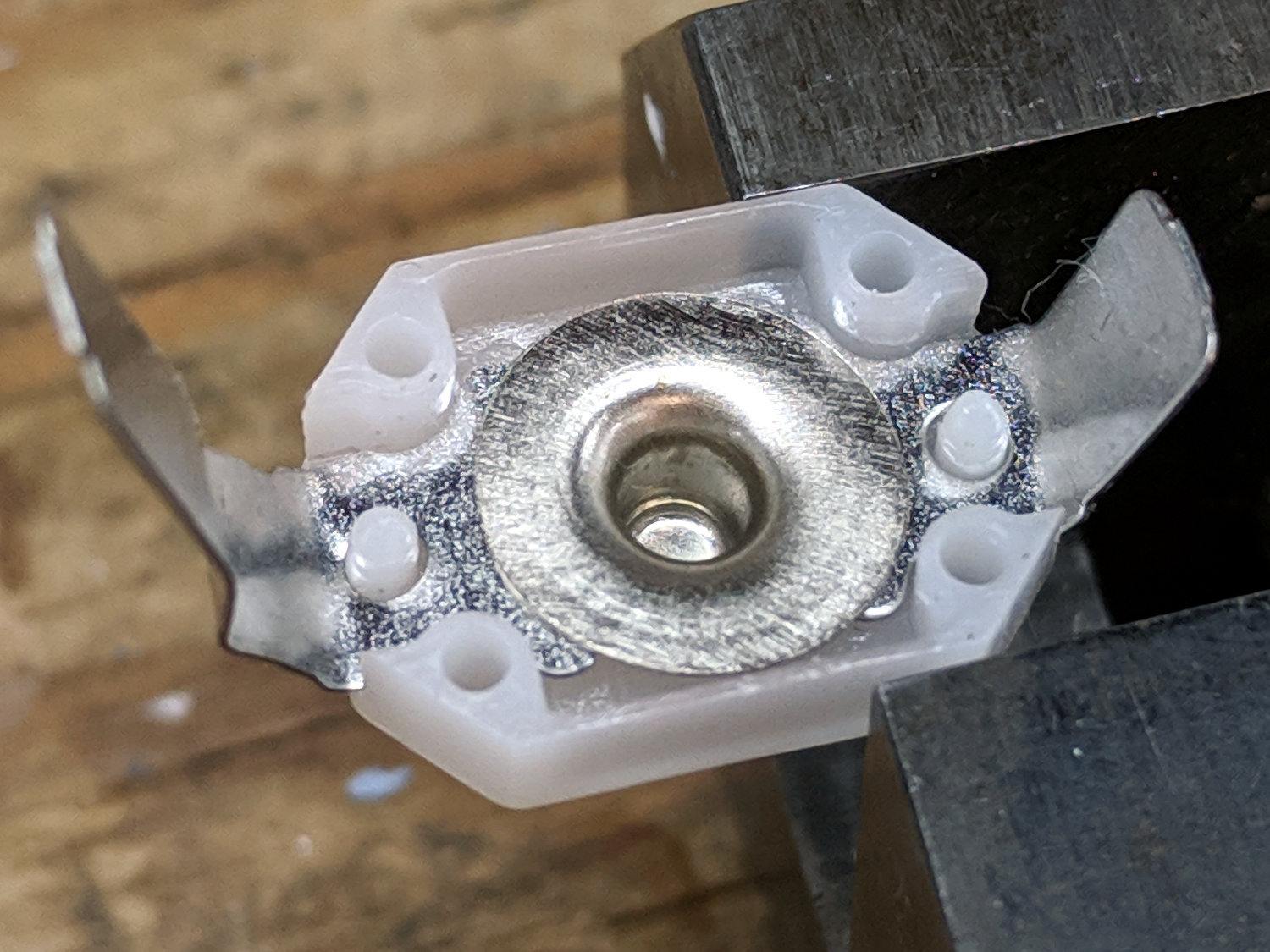
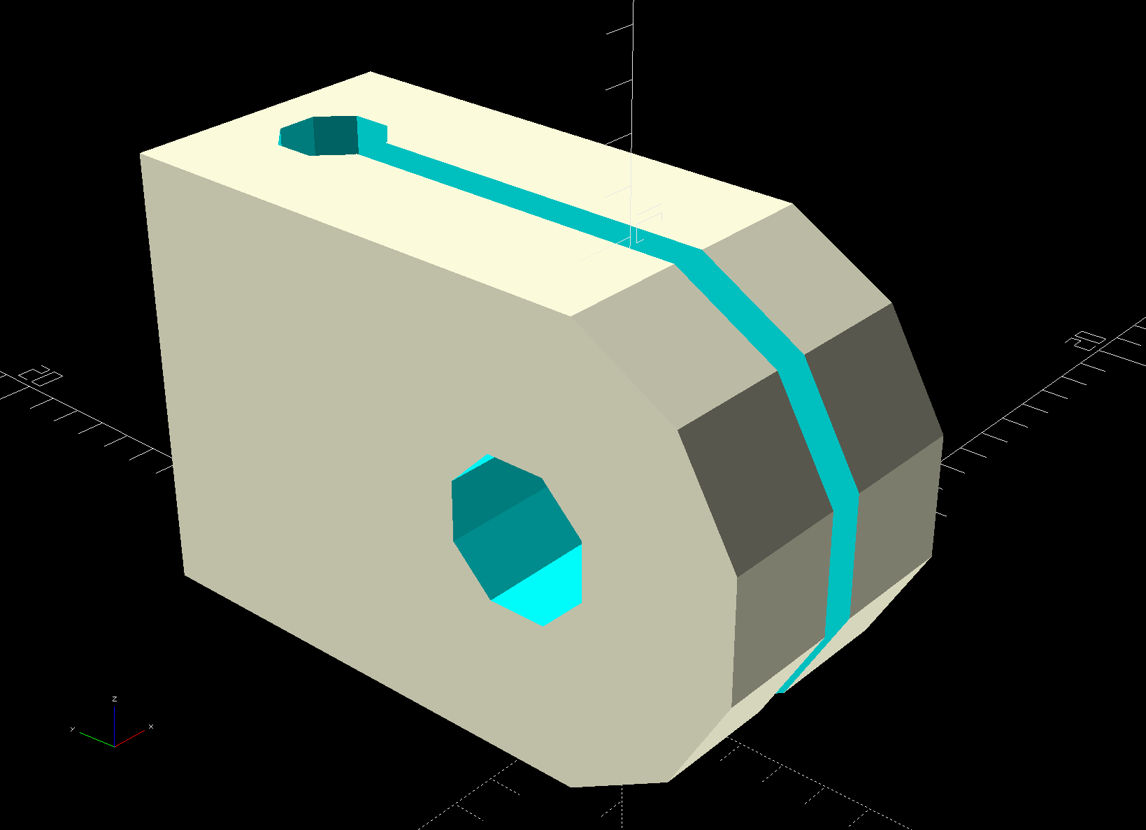
A straightforward cable clip:
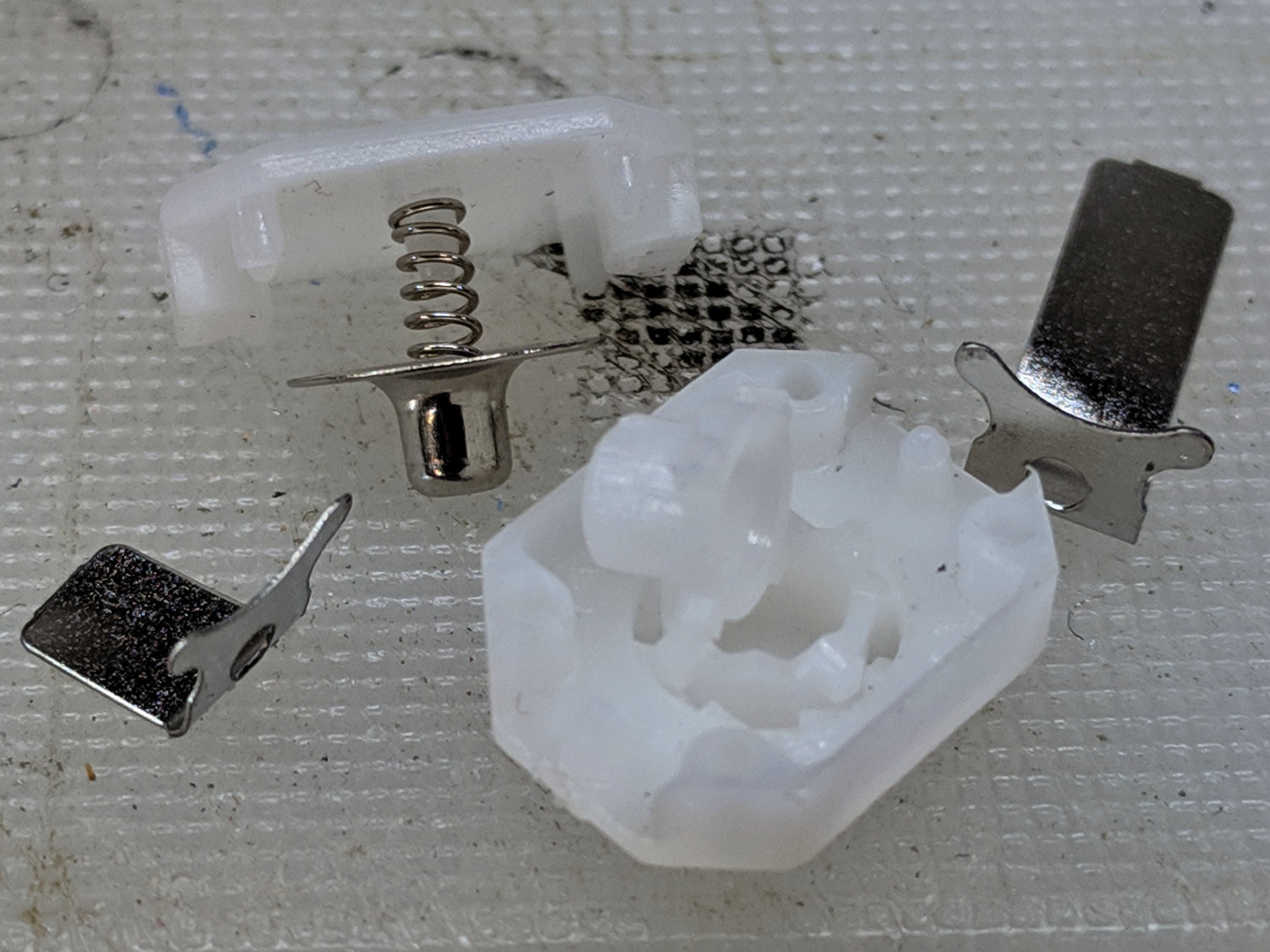
It looks better than the previous hack bent from a snippet of PET clamshell:
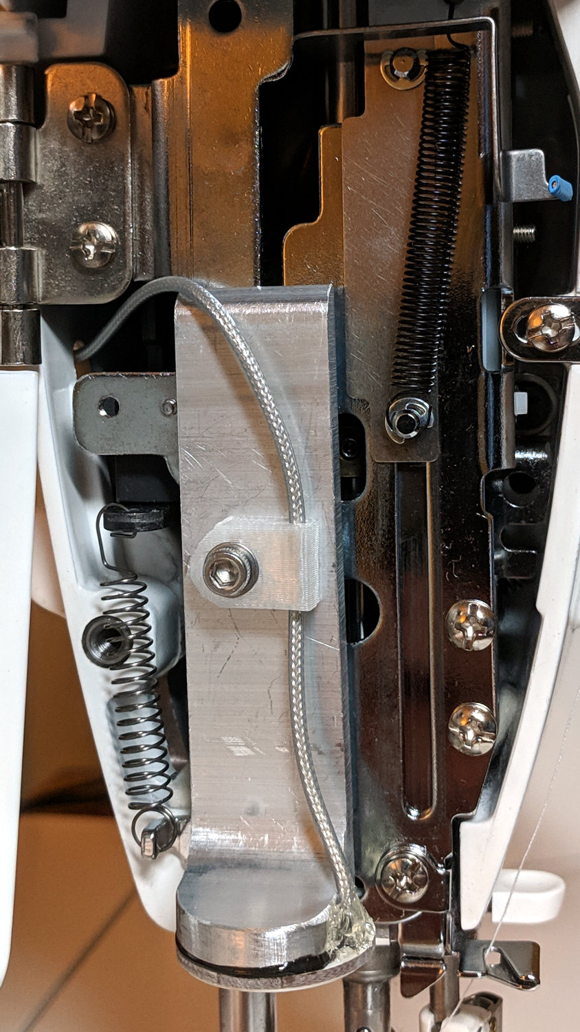
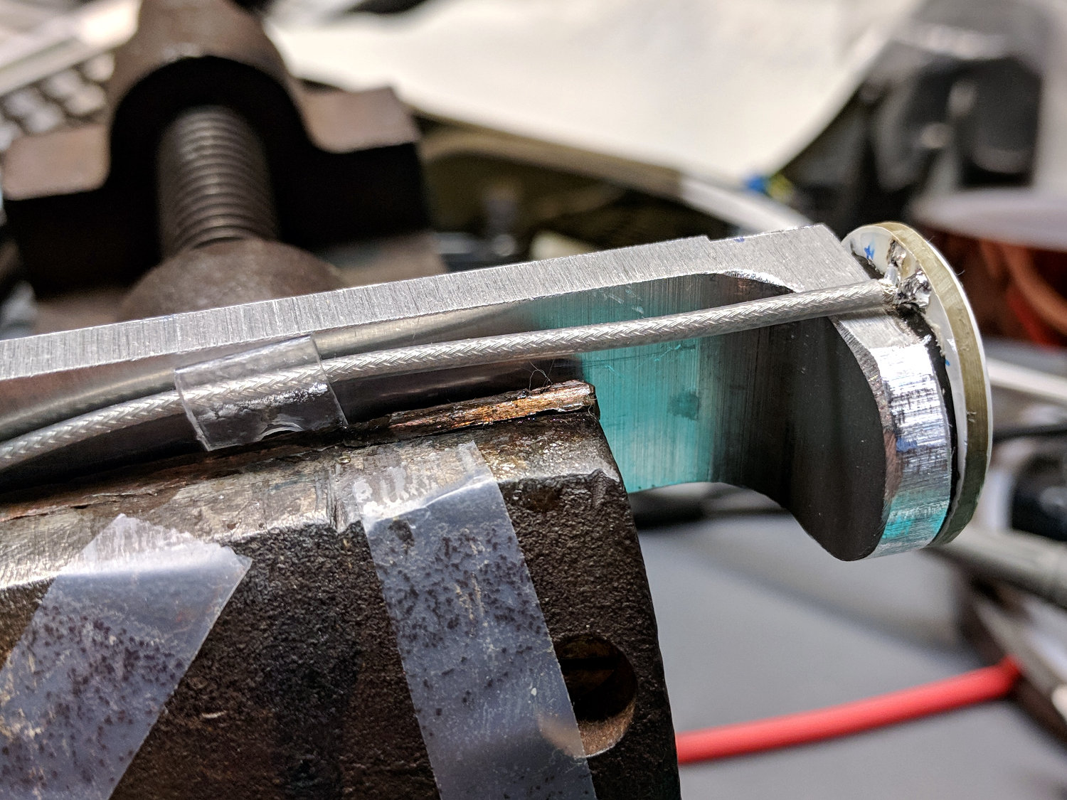
Ream out the holes with suitable drills, clean out the slot using Tiny Bandsaw™, and it’s all good.
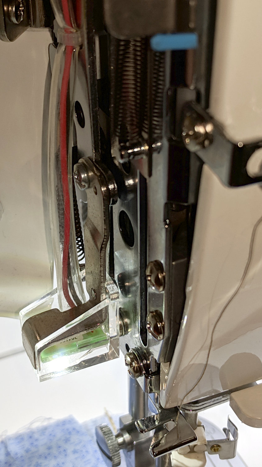
In retrospect, the slot isn’t worth the effort, because it doesn’t open wide enough to admit the cable and doesn’t provide any clamping force; a simple block with two holes would do as well. If the heatsink didn’t already have a 3 mm screw in play, I’d use an adhesive-backed clip from the early Kenmore LEDs.
The OpenSCAD source code isn’t much to look at:
//-----
// Cable clip
// Reoriented into build position, because we only need one

ClipWall = 3*ThreadWidth;
Clip = [15.0,10.0,CableOD + 2*ClipWall];

module CableClip(CableOD = 2.0) {

ClipSides = 4*3;
ClipRadius = Clip.y/2;
ScrewOD = 3.0;
ClipOC = Clip.x - ClipRadius - CableOD/2 - ClipWall;

  translate([0,0,Clip.y/2])
    rotate([90,0,90])
      translate([0,0,0*Clip.z/2])
        difference() {
          union() {
            rotate(180/ClipSides)
              cylinder(d=Clip.y/cos(180/ClipSides),h=Clip.z,$fn=ClipSides,center=true);
            translate([ClipRadius,0,0])
              cube([Clip.x - ClipRadius,Clip.y,Clip.z],center=true);
          }
          translate([0,0,-(Clip.z/2 + Protrusion)])
            rotate(180/8)
              PolyCyl(ScrewOD,Clip.z + 2*Protrusion,8);
          rotate([90,0,0])
            translate([ClipOC,0,-Clip.y])
              rotate(180/8)
              PolyCyl(CableOD,2*Clip.y,8);
          translate([ClipOC - Clip.x/2,0,0])
            cube([Clip.x,2*Clip.y,2*ThreadWidth],center=true);
        }
}