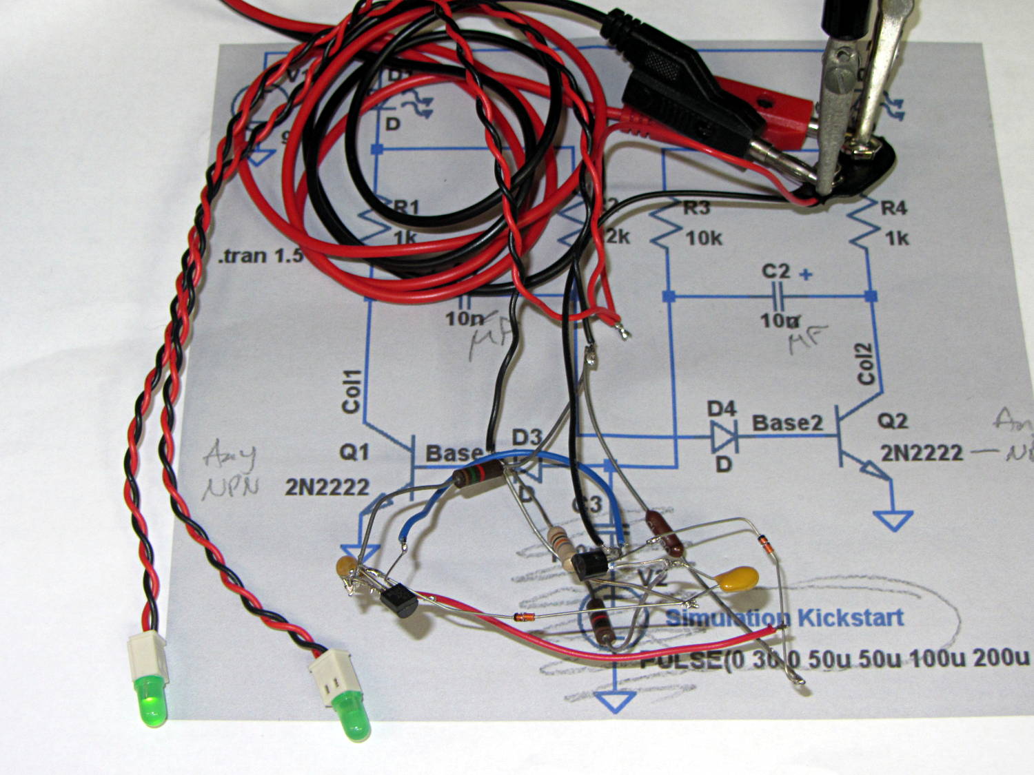
Just to show all those precisely machined enclosures and tidy hand-wired boards don’t count for much:
The schematic again:
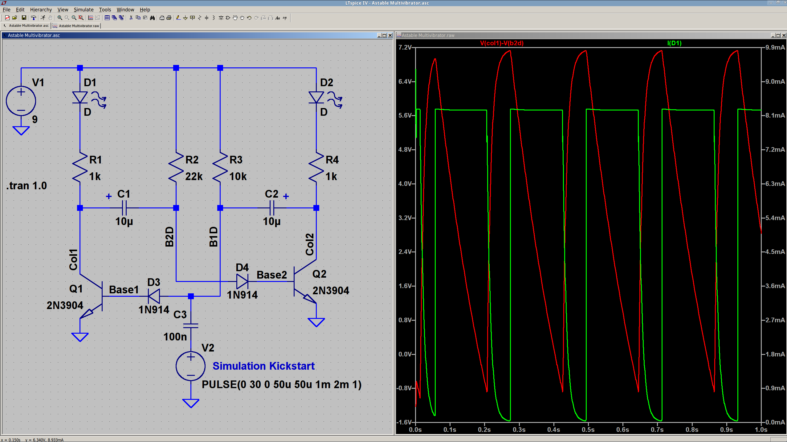
It started with that idea and evolved slightly.
The Smell of Molten Projects in the Morning
Ed Nisley's Blog: Shop notes, electronics, firmware, machinery, 3D printing, laser cuttery, and curiosities. Contents: 100% human thinking, 0% AI slop.
Just to show all those precisely machined enclosures and tidy hand-wired boards don’t count for much:
The schematic again:
It started with that idea and evolved slightly.

Comments
5 responses to “Astable Multivibrator: Hairball Edition”
I’m confused. Where’s the 555? ;-)
A guy I know built a wall-following robot with one transistor (none of this fancy microcontroller stuff for him), so the parts you see here could become a robot controller with redundancy…
Okay, why D3 and D4? I’ve built this circuit many a time, but without them.
The base-emitter junction breaks down at about 6 V reverse bias and there’s no current limiting through the caps when the collectors saturate; IIRC, they don’t quite reach breakdown with a 9 V battery, but the diodes may save some wear & tear.
Makes sense. I’m working off 9V so I didn’t consider reverse bias too deeply.