The Smell of Molten Projects in the Morning

Ed Nisley's Blog: Shop notes, electronics, firmware, machinery, 3D printing, laser cuttery, and curiosities. Contents: 100% human thinking, 0% AI slop.

Category: Electronics Workbench

Electrical & Electronic gadgets

  • Astable Multivibrator: DSO150 vs. Fast Blinky

    A bipolar transistor version of the astable multivibrator with a yellow Pirhana LED required absurdly large capacitors for a reasonable blink rate and, seeing as how I need a demo circuit for Show-n-Tells, it seemed a good candidate for a faster blink. I replaced a 100 µF cap with the 22 µF electrolytic cap from the other side, installed a 2 µF cap (which, judging from the lack of polarity indicators, may be a film cap) from the Squidwrench junk heap parts bin in its place, and hitched up the DSO150 because I brought it along:

    DSO150 with fast LED blinky
    DSO150 with fast LED blinky

    Worked the first time and caught it in mid-blink! [grin]

    The DSO150’s triggering remains a mystery, as it seems difficult to get a stable trace from a perfectly reasonable waveform. The scope didn’t trigger well on the astable’s original seconds-long pulses, perhaps due to a DC blocking cap in the triggering circuitry (whatever it may look like), but this waveform should be dead simple.

    Having gained a visceral understanding of why MOSFET astables produce better battery life, this bipolar transistor design is just a milestone along the way.

  • J5 Tactical Flashlight: Tailcap Switch

    Mashing the LED PCB into place didn’t entirely solve the weak beam problem, so I unscrewed the tailcap holding the switch on the other end of the body:

    J5 Tactical Flashlight - tailcap
    J5 Tactical Flashlight – tailcap

    Unscrewing the lock ring releases the switch assembly:

    J5 Tactical Flashlight - tailcap parts
    J5 Tactical Flashlight – tailcap parts

    I suspect the tab sticking out from the side of the switch doesn’t make / never made good contact with the aluminum tailcap body, but having gone this far there’s no reason to stop. The plastic housing around the spring-loaded brass battery contact pops off to reveal the actual switch:

    J5 Tactical Flashlight - switch contacts
    J5 Tactical Flashlight – switch contacts

    The long tab on the front of the switch sits under the spring, so that’s the negative battery contact. The LED current goes through:

    • battery negative to contact + spring
    • switch tab + moving contact + tab
    • tab to tailcap pressure fit
    • tailcap threads
    • front tube threads
    • LED pill to PCB
    • spring to battery positive

    So. Many. Aluminum. Joints.

    The switch body snaps apart to disgorge a remarkable number of parts:

    J5 Tactical Flashlight - tailcap switch parts
    J5 Tactical Flashlight – tailcap switch parts

    Nothing looked out of order, so I applied a thin layer of DeoxIT Red to all the contacting parts and reassembled everything.

    For the record, the switch’s internal parts have many plausible assembly sequences; the workable one goes a little something like this:

    J5 Tactical Flashlight - tailcap switch contacts
    J5 Tactical Flashlight – tailcap switch contacts

    Contrary to what you (well, I) might think, the switch is off when the central contact is pushed forward, away from the side contacts.

    I bent a slight angle into the tailcap contact (on the right in the picture) to make better / firmer contact with the tailcap body, cleaned all the threads with a cotton swab carrying a dab of DeoxIT, and screwed it all together.

    With everything back together, the beam seems bright and steady again. We’ll see how long it lasts.

  • J5 Tactical Flashlight: Loose PCB

    I’ve been using the J5 Tactical flashlight as a “walking light” on our walks around the neighborhood, because its bright white spot has definitely caused a few drivers to look up from their phones at the last moment and swerve away.

    Of late, however, it turned on with a weak light and operated erratically. Removing the lens and unscrewing the front end revealed one mmmm potential problem:

    J5 Tactical Flashlight - loose LED PCB
    J5 Tactical Flashlight – loose LED PCB

    It looks like they’re depending on the “gold” in cutaway plated-through holes to make electrical contact with the aluminum mount, then through the threads to the case. The PCB joint would work much better with consistent pressure all the way around its perimeter.

    I mashed the PCB into place with a machinists vise, but, given the number of problems I’ve had with J5 flashlights (one a QC reject), they’re on my Non-Preferred Vendor list; if I’m going to get junk, I may as well pay bottom dollar.

  • Juki TL-2010Q LED

    For the record, Juki thinks this SMD LED provides enough light around the needle of Mary’s TL-2010Q sewing machine:

    Juki TL-2010Q - OEM LED light
    Juki TL-2010Q – OEM LED light

    A detailed look at the active ingredient:

    Juki TL-2010Q - OEM SMD LED
    Juki TL-2010Q – OEM SMD LED

    The 30 Ω resistor drops exactly 2.0 V, so the white LED runs at 67 mA.

    We think it’s a glowworm, compared to the COB LED bar across the back of the arm:

    Juki TL-2010Q COB LED - installed - rear view
    Juki TL-2010Q COB LED – installed – rear view

    I can do better than that, although not with juice from their 5 V power supply.

  • Sony NP-FS11 Battery Rebuild: 2019

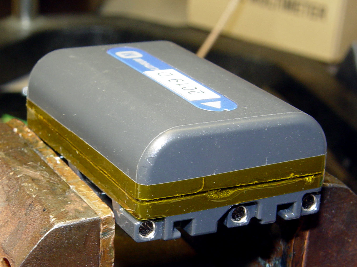
    Three years on, it’s time to rebuild some NP-FS11 lithium battery packs for the ancient Sony F505V camera, starting with packs I’ve rebuilt several times before and the last four cells from 2016.

    The final test shows the 2011-F pack may power an LED blinky, but not much else:

    NP-FS11 - 2011-F 2016-GH - 2019-02-19
    NP-FS11 – 2011-F 2016-GH – 2019-02-19

    Although the total capacity is still about 1.3 A·h for the two best batteries, the camera says the weakest two are dead after a few photos.

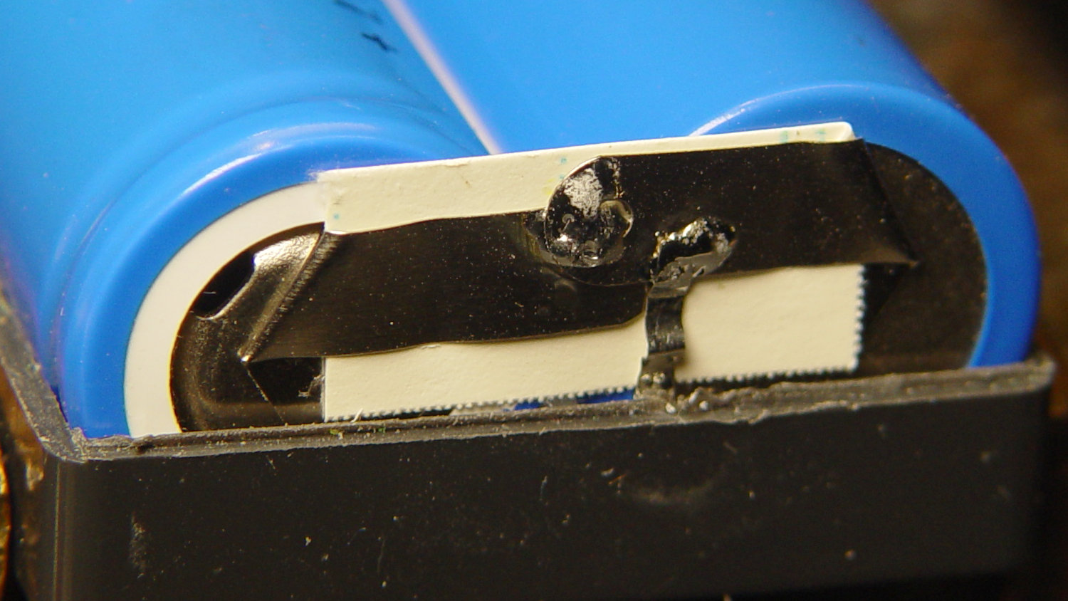
    For reference while resoldering, the joints at the negative terminals:

    NP-FS11 battery rebuld - negative terminals
    NP-FS11 battery rebuld – negative terminals

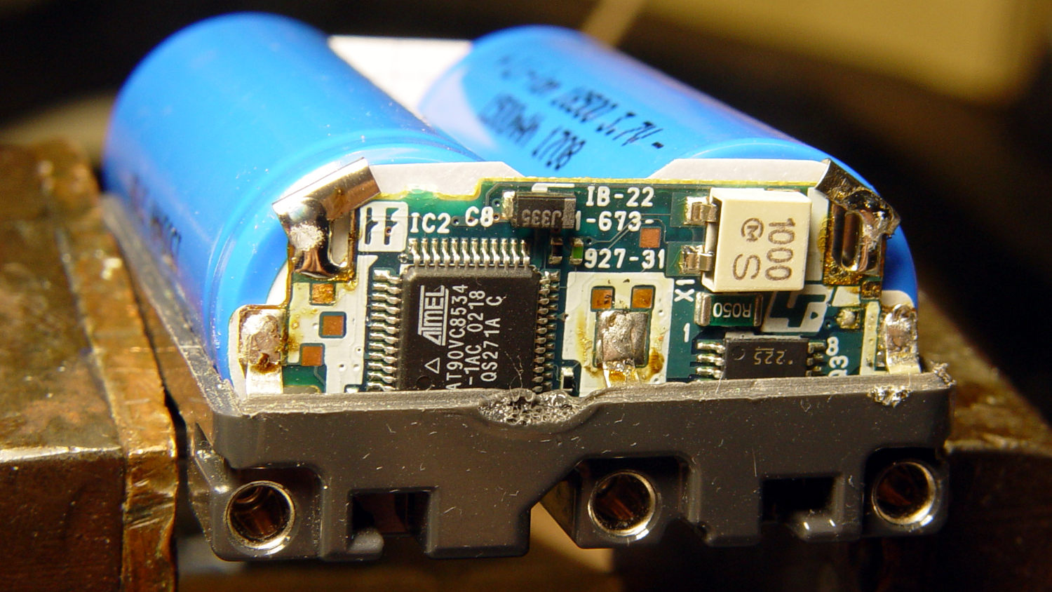
    And the protection PCB on the positive end:

    NP-FS11 battery rebuld - positive terminals
    NP-FS11 battery rebuld – positive terminals

    Unsolder the strap in the middle and the B+ positive connection on the right side to remove the cells.

    If cameras used bare cells, rather than glued-shut “proprietary” packs with super-secret unique ID ROMs, they’d be easier to keep running. My Sony DSC-H5 has other problems, but NiMH AA cells are easy to find.

  • Sewing Machine Light Bar Current

    After more use and brightness tweaking, the COB light bars on the Juki TL-2010Q and Kenmore 158 now have 2.2 Ω ballast resistors setting the LED current to 370 mA and 300 mA, respectively:

    Juki TL-2010Q COB LED - 2.2 ohm header
    Juki TL-2010Q COB LED – 2.2 ohm header

    Changing from 2.0 Ω to 2.2 Ω produces a noticeable decrease in light, so 10% steps around 2 Ω seem to be about the right increment. The COB LED strips claim 6 W at 12 V = 500 mA nominal, so they’re running well under the spec.

    Given that cheap 1% metal film resistor assortments use E6 or E12 value steps, at best, we may need two resistors in parallel for the next adjustments.

  • SJCAM M20 Camera: Tour Easy Seat Mount

    The general idea is to replace this:

    M20 in waterproof case - Tour Easy seat
    M20 in waterproof case – Tour Easy seat

    With this:

    SJCAM M20 Mount - Tour Easy side view
    SJCAM M20 Mount – Tour Easy side view

    Thereby solving two problems:

    • Pitifully small battery capacity
    • Wobbly camera support

    The battery is an Anker PowerCore 13000 Power Bank plugged into the M20’s USB port. Given that SJCAM’s 1 A·h batteries barely lasted for a typical hour of riding, the 13 A·h PowerCore will definitely outlast my legs. The four blue dots just ahead of the strap around the battery show it’s fully charged and the blue light glowing through the case around the M20 indicates it’s turned on.

    The solid model has four parts:

    SJCAM M20 Mount - Fit layout
    SJCAM M20 Mount – Fit layout

    Which, as always, incorporates improvements based on the actual hardware on the bike.

    A strap-and-buckle belt harvested from a defunct water pack holds the battery into the cradle and the cradle onto the rack, with a fuzzy velcro strip stuck to the bottom to prevent sliding:

    SJCAM M20 Mount - Tour Easy rear view
    SJCAM M20 Mount – Tour Easy rear view

    The shell around the camera is basically a box minus the camera:

    SJCAM M20 Mount - Show - shell
    SJCAM M20 Mount – Show – shell

    The shell builds as three separate slabs, with the center section having cutouts ahead of the camera’s projections to let it slide into place:

    SJCAM M20 Mount - Show - shell sections
    SJCAM M20 Mount – Show – shell sections

    The new shell version is 30.5 mm thick, so a 40 mm screw will stick out maybe 5 mm beyond the nylon locknut. I trust the screws will get lost in the visual noise of the bike.

    A peg sticking out behind the USB jack anchors the cable in place:

    SJCAM M20 Mount - Show - shell sections - USB side
    SJCAM M20 Mount – Show – shell sections – USB side

    The front slab and center top have curves matching the M20 case:

    SJCAM M20 Mount - Show - shell sections - button side
    SJCAM M20 Mount – Show – shell sections – button side

    The camera model has a tidy presentation option:

    SJCAM M20 Mount - Show - M20 body
    SJCAM M20 Mount – Show – M20 body

    And an ugly option to knock the protruberances out of the shell:

    SJCAM M20 Mount - Show - M20 body - knockouts
    SJCAM M20 Mount – Show – M20 body – knockouts

    The square-ish post on the base fits into an angled socket in the clamp around the seat rail:

    SJCAM M20 Mount - Show - clamp
    SJCAM M20 Mount – Show – clamp

    The numbers correspond to the “Look Angle” of the socket pointing the camera toward overtaking traffic. The -20° in the first clamp shows a bit too much rack:

    SJCAM M20 Mount - first ride - traffic - 2019-02-06
    SJCAM M20 Mount – first ride – traffic – 2019-02-06

    It may not matter, though, as sometimes you want to remember what’s on the right:

    SJCAM M20 Mount - first ride - 2019-02-06
    SJCAM M20 Mount – first ride – 2019-02-06

    FWIW, the track veering off onto the grass came from a fat-tire bike a few days earlier. Most of the rail trail had cleared by the time we tried it, with some ice and snow in rock cuts and shaded areas.

    Contrary to the first picture, I later remounted the camera under the seat rail with its top side downward. The M20 has a “rotate video” mode for exactly that situation, which I forgot to turn off in the fancy new mount, so I rotated the pix afterward.

    A 3 mm screw extends upward through the hole in the socket to meet a threaded brass insert epoxied into the shell base, as shown in the uglified M20 model. Despite appearances, the hole is perpendicular to both the socket and the shell, so you can tweak the Look Angle without reprinting the shell.

    All in all, the mount works well. We await better riding weather …

    The OpenSCAD source code as a GitHub Gist:

    // SJCAM M20 Camera Mount for Tour Easy seat back rail
    // Ed Nisley – KE4ZNU
    // 2019-02
    /* [Layout Options] */
    Layout = "Fit"; // [Show,Fit,Build]
    Part = "Shell"; // [Cradle,Shell,Clamp,ShellSections,M20,Interposer,Battery,Buttons]
    LookAngle = [0,5,-25]; // camera angle, looking backwards
    /* [Extrusion Parameters] */
    ThreadWidth = 0.40;
    ThreadThick = 0.25;
    HoleWindage = 0.2;
    Protrusion = 0.1;
    //—–
    // Dimensions
    /* [Hidden] */
    ID = 0;
    OD = 1;
    LENGTH = 2;
    ClampScrew = [5.0,10.0,50.0]; // ID=thread OD=washer LENGTH=total
    ClampInsert = [5.0,7.5,10.5]; // brass insert
    MountScrew = [3.0,7.0,23]; // ID=thread OD=washer LENGTH=tune to fit clamp arch
    MountInsert = [3.0,4.95,8.0]; // ID=screw OD, OD=knurl dia
    EmbossDepth = 2*ThreadThick + Protrusion; // recess depth + Protrusion beyond surface
    DebossHeight = EmbossDepth; // text height + Protrusion into part
    Projection = 10; // stick-out to punch through shell sides & suchlike
    SupportColor = "Yellow";
    FadeColor = "Green";
    FadeAlpha = 0.25;
    //—–
    // Useful routines
    function IntegerMultiple(Size,Unit) = Unit * ceil(Size / Unit);
    module PolyCyl(Dia,Height,ForceSides=0) { // based on nophead's polyholes
    Sides = (ForceSides != 0) ? ForceSides : (ceil(Dia) + 2);
    FixDia = Dia / cos(180/Sides);
    cylinder(r=(FixDia + HoleWindage)/2,
    h=Height,
    $fn=Sides);
    }
    //—–
    // M20 Camera
    // Looks backwards from seat = usual right-hand coordinates work fine
    // X parallel to bike frame, Y parallel to seat strut, Z true vertical
    M20 = [24.5,40.5,54.0];
    M20tm = 4.0; // chord height at top of case
    M20tr = (pow(M20tm,2) + pow(M20.y,2)/4) / (2*M20tm); // … radius
    echo(str("Top radius: ",M20tr));
    M20TopSides = 3*3*4;
    echo(str(" … sides: ",M20TopSides));
    M20fm = 1.0; // chord height at front of case
    M20fr = (pow(M20fm,2) + pow(M20.y,2)/4) / (2*M20fm); // … radius
    echo(str("Front radius: ",M20fr));
    M20FrontSides = ceil(M20fr / M20tr * M20TopSides); // make arc sides match up
    echo(str(" … sides: ",M20FrontSides));
    Lens = [19.0,22.5,5.5]; // ID=optical element, OD=tube
    LensBezel = [23.0,24.5,2.5]; // ID=lens tube, OD=bezel
    LensOffset = [-M20fm,0,41.5]; // bottom of case to lens centerline
    LensCap = [Lens[OD],24.5,4.5]; // silicone lens cap
    Spkr = [0.75,M20.y,14.3]; // speaker recess below LCD
    Switch = [8.0,1.0,38.0]; // selection switches
    SwitchOffset = [9.0,0,0]; // from rear to center of switches
    Jack = [10.0,0.1,36.0]; // jack and MicroSD card access, slightly enlarged
    JackOffset = [10.0,0,30.0]; // rear, bottom to center of jack block
    USB = [JackOffset.x – Jack.x/2,20.0,10.0]; // strut under USB plug
    USBOffset = [0,0,33.5]; // bottom to center of jack
    SDCard = [2.0,0.1,12.0]; // SD Card slot
    SDOffset = [9.0,0,20.0]; // bottom, rear to center of slot
    Button = [8.5,10.5,M20tm]; // ID = button, OD = bezel
    ButtonOC = 18.0; // on-center Y separation, assume X centered
    Screen = [0.1,31,24]; // LCD on rear face
    ScreenOffset = [0,0,33];
    BarLEDs = [0.1 + M20fm,12.0,5.0]; // Bar LEDs on front face
    BarLEDsOffset = [-M20fm,0,12.5];
    PwrLED = [3.5,3.5,0.1 + M20tm]; // power LED on top
    PwrLEDOffset = [2.5,0,0];
    RearLEDs = [1.0,2.0,0.1]; // charge and power LED openings above LCD
    RearLEDsOffset = [0,13.0/2,M20tm + 3.0]; // .. from top center of case
    module Buttons(KO) {
    for (j = [-1,1])
    translate([0,j*ButtonOC/2,0]) {
    cylinder(d=Button[OD],h=Button[LENGTH],$fn=12);
    if (KO)
    translate([0,0,M20tm])
    cylinder(d1=Button[OD],d2=1.5*Button[OD],h=Button.z,$fn=12);
    }
    }
    module M20Shape(Knockout = false) {
    difference() {
    intersection() {
    translate([0,0,M20.z/2 – M20tr]) // top curve
    rotate([0,90,0]) rotate(180/M20TopSides)
    cylinder(r=M20tr,h=2*(M20.x + Protrusion),$fn=M20TopSides,center=true);
    translate([M20.x/2 – M20fr,0,0])
    rotate(180/M20FrontSides)
    cylinder(r=M20fr,h=2*M20.z,$fn=M20FrontSides,center=true);
    cube(M20,center=true);
    }
    translate([Spkr.x/2 – M20.x/2 – Protrusion,0,Spkr.z/2 – Protrusion/2 – M20.z/2])
    cube(Spkr + [Protrusion,2*Protrusion,Protrusion],center=true);
    }
    translate([M20.x/2,0,-M20.z/2] + LensOffset)
    rotate([0,90,0])
    cylinder(d=Lens[OD] + HoleWindage,h=(Knockout ? Projection : Lens[LENGTH]),$fn=4*4*3,center=false);
    translate([M20.x/2 + M20fm/2,0,-M20.z/2] + LensOffset) // lens bezel
    rotate([0,90,0])
    cylinder(d1=LensBezel[OD],d2=Lens[OD],h=LensBezel[LENGTH],$fn=4*4*3,center=false);
    translate([-M20.x/2 + SwitchOffset.x, // side switches
    -(Switch.y + M20.y – Protrusion)/2,
    0])
    cube(Switch + [0,Protrusion,0] + (Knockout ? [0,Projection,0] : [0,0,0]),center=true);
    if (Knockout)
    translate([(M20.x/2 – M20fm)/2,-M20.y/2,0]) // side switch slide-in clearance
    cube([M20.x/2 – M20fm,2*Switch.y,Switch.z],center=true);
    translate([-M20.x/2 + JackOffset.x,
    (Jack.y + M20.y – Protrusion)/2,
    JackOffset.z – M20.z/2])
    cube(Jack + [0,Protrusion,0] + (Knockout ? [0,Projection,0] : [0,0,0]),center=true);
    translate([0,0,M20.z/2 – M20tm]) // top control buttons
    Buttons(Knockout);
    if (Knockout)
    translate([(M20.x – M20fm)/4,0,M20.z/2 – M20tm + Button[LENGTH]/2]) // slide-in button clearance
    cube([(M20.x – M20fm)/2,ButtonOC + Button[OD],Button[LENGTH]],center=true);
    translate([-(M20.x + Screen.x – Protrusion)/2,0,-M20.z/2] + ScreenOffset)
    cube(Screen + [Protrusion,0,0] + (Knockout ? [Projection,0,0] : [0,0,0]),center=true);
    for (j = [-1,1])
    translate([-M20.x/2 + Protrusion,j*RearLEDsOffset.y,M20.z/2 – RearLEDsOffset.z])
    rotate([0,-90,0]) rotate(180/6)
    PolyCyl(RearLEDs[OD],Knockout ? Projection : RearLEDs[LENGTH],6);
    translate([M20.x/2 + BarLEDs.x/2,0,-M20.z/2] + BarLEDsOffset)
    cube(BarLEDs + (Knockout ? [Projection,0,0] : [0,0,0]),center=true);
    translate([0,0,M20.z/2 – M20tm] + PwrLEDOffset)
    rotate(180/8)
    PolyCyl(PwrLED[OD],(Knockout ? Projection : PwrLED[LENGTH]),8);
    if (Knockout) {
    translate([0,0,-M20.z/2])
    rotate([180,0,0]) { // mounting screw
    PolyCyl(MountScrew[ID],MountScrew[LENGTH],6);
    translate([0,0,MountScrew[LENGTH] – Protrusion])
    PolyCyl(MountScrew[OD],MountScrew[ID] + 4*ThreadThick,6); // SHCS head is about 1 ID long
    }
    translate([0,0,-(M20.z/2 + MountInsert[LENGTH] + 4*ThreadWidth – Protrusion)])
    PolyCyl(MountInsert[OD],MountInsert[LENGTH] + 4*ThreadWidth,6); // insert inside Interposer
    }
    }
    //—–
    // Shell
    // Wraps around camera
    NomWall = 3.0;
    ShellWall = [IntegerMultiple(NomWall,ThreadThick),
    IntegerMultiple(NomWall,ThreadWidth),
    IntegerMultiple(NomWall,ThreadWidth)];
    ShellRadius = ShellWall.x;
    ShellSides = 8;
    ShellOA = M20 + 2*ShellWall;
    echo(str("Shell OA: ",ShellOA));
    Interposer = [M20.x – M20fm,M20.x – M20fm,10.0]; // if you can't be smart, be square
    module Shell() {
    Screw = [3.0,6.75,30]; // ID=thread OD=washer LENGTH
    ScrewClear = 1.0; // additional washer clearance
    ScrewSides = 8;
    ScrewOC = M20 + [0,Screw[ID]/cos(180/ScrewSides),Screw[ID]/cos(180/ScrewSides)]; // use PolyCyl hole dia, ignore .x value
    difference() {
    union() {
    hull()
    for (i=[-1,1], j=[-1,1], k=[-1,1])
    translate([i*(ShellOA.x – 2*ShellRadius)/2,
    j*(ShellOA.y – 2*ShellRadius)/2,
    k*(ShellOA.z – 2*ShellRadius)/2])
    sphere(r=ShellRadius/cos(180/ShellSides),$fn=ShellSides); // fix low-poly approx radius
    for (j=[-1,1], k=[-1,1]) // screw bosses, full length
    translate([0,j*ScrewOC.y/2,k*ScrewOC.z/2])
    rotate([0,90,0]) rotate(180/ScrewSides)
    cylinder(d=Screw[OD] + ScrewClear,h=ShellOA.x,center=true,$fn=ScrewSides);
    translate([-(ShellOA.x – USB.x – ShellWall.x)/2, // USB plug support strut
    (M20.y + USB.y)/2 – ShellRadius,
    -M20.z/2] + USBOffset)
    hull()
    for (i=[-1,1], j=[-1,1], k=[-1,1])
    translate([i*(USB.x + ShellWall.x – 2*ShellRadius)/2,
    j*(USB.y – 2*ShellRadius)/2,
    k*(USB.z – 2*ShellRadius)/2])
    rotate(0*180/ShellSides) rotate([90,0,90])
    sphere(r=ShellRadius/cos(180/ShellSides),$fn=ShellSides);
    translate([-M20fm/2,0,-ShellOA.z/2 – Interposer.z + Protrusion/2])
    InterposerShape(Embiggen = false);
    }
    render(convexity=4) // remove camera shape from interior
    M20Shape(Knockout = true);
    for (j=[-1,1], k=[-1,1]) // screw bores
    translate([-ShellOA.x,j*ScrewOC.y/2,k*ScrewOC.z/2])
    rotate([0,90,0]) rotate(180/ScrewSides)
    PolyCyl(Screw[ID],2*ShellOA.x,ScrewSides);
    translate([ShellOA.x/2 – ThreadThick + Protrusion/2,0,-5]) // recess for legend
    cube([EmbossDepth,ShellOA.y – 12,7],center=true);
    translate([0,(M20.y + 1.5*SDCard.z)/2 + ThreadWidth,-M20.z/2 + SDOffset.z])
    resize([M20.x,0,0])
    sphere(d=1.5*SDCard.z,$fn=24);
    }
    translate([ShellOA.x/2 – DebossHeight,0,-5])
    rotate([90,0,90])
    linear_extrude(height=DebossHeight,convexity=20)
    text(text="KE4ZNU",size=5,spacing=1.20,font="Arial:style:Bold",halign="center",valign="center");
    // Totally ad-hoc support structures
    if (false)
    color(SupportColor) {
    for (j=[-1,1], k=[0,1])
    translate([-ShellOA.x/2 + Screw[LENGTH],j*ShellOA.y/2,k*ShellOA.z])
    rotate([0,90,0])
    SupportScrew(Dia=Screw[OD] + ScrewClear,Length=ShellOA.x – Screw[LENGTH],Num=ScrewSides);
    }
    }
    // Generate support structure for screw boss
    module SupportScrew(Dia,Length,Num = 6) {
    for (a=[0 : 360/Num : 360/2])
    rotate(a)
    translate([0,0,(Length + ThreadThick)/2])
    cube([Dia – 2*ThreadWidth,2*ThreadWidth,Length – ThreadThick],center=true);
    }
    // Generate interposer block
    // Origin at center bottom surface for E-Z rotation
    module InterposerShape(Embiggen = false) {
    translate([0,0,Interposer.z/2])
    if (Embiggen) {
    minkowski() {
    cube(Interposer,center=true);
    cube(HoleWindage,center=true);
    }
    }
    else
    cube(Interposer + [-Protrusion,0,Protrusion],center=true); // avoid slivers, merge with shell
    }
    // Cut shell sections for printing
    // "Front" = lens end, toward +X direction
    // origin centered on M20.xyz and ShellOA.xyz
    module ShellSection(Section="Front") {
    if (Section == "Front") // include front curve
    intersection() {
    Shell();
    translate([ShellOA.x – (M20fm + ShellWall.x),0,0])
    cube([ShellOA.x,2*ShellOA.y,2*ShellOA.z],center=true);
    }
    else if (Section == "Center") // exclude front curve for E-Z printing
    intersection() {
    Shell();
    translate([-M20fm/2,0,0])
    cube([M20.x – M20fm,2*ShellOA.y,2*ShellOA.z],center=true);
    }
    else if (Section == "Back") // flush with LCD on rear face
    intersection() {
    Shell();
    translate([-ShellOA.x + (ShellWall.x),0,0])
    cube([ShellOA.x,2*ShellOA.y,2*ShellOA.z],center=true);
    }
    }
    //—–
    // Clamp
    // Grips seat frame rail
    // Uses shell rounding values for tidiness
    // Adjust MountScrew[LENGTH] to put head more-or-less flush with clamp arch
    RailOD = 20.0; // slightly elliptical in bent section
    RailSides = 2*3*4;
    ClampOA = [60.0,40.0,ClampScrew[LENGTH]]; // set clamp size to avoid weird screw spacing
    echo(str("Clamp OA: ",ClampOA));
    ClampOffset = 0.0; // raise clamp to allow more room for mount
    ClampTop = ClampOA.z/2 + ClampOffset;
    InsertCap = 6*ThreadThick; // fill layers atop inserts
    Kerf = 2.0;
    module Clamp(Support = false) {
    RibThick = 2*ThreadWidth;
    NumRibs = IntegerMultiple(ceil(ClampOA.y / 4.0),2); // space ribs roughly 4 mm apart
    RibSpace = ClampOA.y / NumRibs;
    echo(str("Ribs: ",NumRibs," spaced: ",RibSpace));
    ClampScrewOC = IntegerMultiple(ClampOA.x – ClampScrew[OD] – 10*ThreadWidth,1.0);
    echo(str("ClampScrew OC: ",ClampScrewOC));
    difference() {
    hull()
    for (i=[-1,1], j=[-1,1], k=[-1,1])
    translate([i*(ClampOA.x – 2*ShellRadius)/2,
    j*(ClampOA.y – 2*ShellRadius)/2,
    k*(ClampOA.z – 2*ShellRadius)/2 + ClampOffset])
    sphere(r=ShellRadius/cos(180/ShellSides),$fn=ShellSides);
    cube([2*ClampOA.x,2*ClampOA.y,Kerf],center=true); // split across middle
    rotate([90,0,0]) // seat rail
    cylinder(d=RailOD,h=2*ClampOA.y,$fn=RailSides,center=true);
    for (i=[-1,1]) // clamp inserts
    translate([i*ClampScrewOC/2,0,0])
    rotate(180/6)
    PolyCyl(ClampInsert[OD],ClampTop – InsertCap,6);
    for (i=[-1,1]) // clamp screw clearance
    translate([i*ClampScrewOC/2,0,-(ClampOA.z/2 – ClampOffset) – InsertCap])
    rotate(180/6)
    PolyCyl(ClampScrew[ID],ClampOA.z,6);
    translate([0,0,ClampTop + 0.7*Interposer.z]) // mounting bolt hole
    rotate(LookAngle)
    translate([0,0,ShellOA.z/2]) {
    M20Shape(Knockout = true);
    translate([0,0,-ShellOA.z/2 – Interposer.z])
    InterposerShape(Embiggen = true);
    }
    translate([ClampOA.x/2 – (EmbossDepth – Protrusion)/2, // recess for LookAngle.z
    0,
    ClampOA.z/4 + ClampOffset])
    cube([EmbossDepth,17,8],center=true);
    translate([0.3*ClampOA.x, // recess for LookAngle.z
    -(ClampOA.y/2 – (EmbossDepth – Protrusion)/2),
    ClampOA.z/4 + ClampOffset])
    cube([10,EmbossDepth,8],center=true);
    translate([0,0,-ClampOA.z/2 + (EmbossDepth – Protrusion)/2]) // recess bottom legend
    cube([35,10,EmbossDepth],center=true);
    }
    translate([ClampOA.x/2 – DebossHeight,0,ClampOA.z/4 + ClampOffset]) // LookAngle.z legend
    rotate([90,0,90])
    linear_extrude(height=DebossHeight,convexity=20)
    text(text=str(LookAngle.z),size=6,spacing=1.20,
    font="Arial:style:Bold",halign="center",valign="center");
    translate([0.3*ClampOA.x,-ClampOA.y/2 + DebossHeight + Protrusion/2,ClampOA.z/4 + ClampOffset]) // LookAngle.y legend
    rotate([90,0,00])
    linear_extrude(height=DebossHeight,convexity=20)
    text(text=str(LookAngle.y),size=6,spacing=1.20,
    font="Arial:style:Bold",halign="center",valign="center");
    translate([0,0,-ClampOA.z/2])
    linear_extrude(height=DebossHeight,convexity=20)
    mirror([0,1,0])
    text(text="KE4ZNU",size=5,spacing=1.20,
    font="Arial:style:Bold",halign="center",valign="center");
    if (Support) {
    difference() {
    color(SupportColor)
    union() {
    for (j=[-NumRibs/2:NumRibs/2])
    translate([0,j*RibSpace,0])
    rotate([90,0,0])
    cylinder(d=RailOD – 2*ThreadThick,h=RibThick,$fn=2*3*4,center=true);
    cube([RailOD – 4*ThreadWidth,NumRibs*RibSpace,Kerf + 2*ThreadThick],center=true);
    }
    cube([2*ClampOA.x,2*ClampOA.y,Kerf],center=true); // split across middle
    }
    }
    }
    //—–
    // Battery
    // Based on Anker PowerCore, simplified shapes
    // Includes port & button punchouts
    Battery = [97.5,80.0,22.5]; // X=length, Y includes rounded edges, Z = Y dia
    module BatteryShape() {
    USB = [Projection,38,10]; // clearance around USB output ports
    USBOffset = [0,25.5,0]; // from -Y edge to center of USB block
    ChargeBtn = [11.0 + 5.0,10,5.0 + 5.0]; // charge level check button, enlarged
    Btnc = ChargeBtn.z; // figure button recess into battery curve
    Btnr = Battery.z/2;
    Btnm = Btnr – sqrt(pow(Btnr,2) – pow(Btnc,2)/4);
    ChargeBtnOffset = [17.0,0,0]; // from +X edge to center, centered on Z
    BatterySides = 2*3*4;
    hull()
    for (j=[-1,1])
    translate([0,j*(Battery.y – Battery.z)/2,0])
    rotate([0,90,0])
    cylinder(d=Battery.z,h=Battery.x,$fn=BatterySides,center=true);
    translate([(Battery.x + USB.x)/2 – Protrusion,-Battery.y/2 + USBOffset.y,0])
    cube(USB,center=true);
    translate([Battery.x/2 – ChargeBtnOffset.x,Battery.y/2 + ChargeBtn.y/2 – 2*Btnm,0])
    cube(ChargeBtn,center=true);
    }
    //—–
    // Battery cradle
    RackWidth = 89.0; // flat width between rack rails
    CradleWall = [4.0,4.0,3.0]; // wall thickness
    CradleRadius = 2.0; // corner rounding
    CradlePad = 0.5; // cushion around battery
    BatteryBase = CradleWall.z + CradlePad; // actual bottom surface of battery
    CradleOA = [Battery.x + 2*CradleWall.x,
    min((Battery.y + 2*CradleWall.y),RackWidth),
    BatteryBase + Battery.z/3];
    echo(str("Cradle OA: ",CradleOA));
    module Cradle() {
    difference() {
    hull()
    for (i=[-1,1], j=[-1,1]) { // box with tidy rounded corners
    translate([i*(CradleOA.x/2 – CradleRadius),
    j*(CradleOA.y/2 – CradleRadius),
    1*(CradleOA.z – CradleRadius)])
    sphere(r=CradleRadius,$fn=6);
    translate([i*(CradleOA.x/2 – CradleRadius),
    j*(CradleOA.y/2 – CradleRadius),
    0*(CradleOA.z/2 – CradleRadius)])
    cylinder(r=CradleRadius,h=CradleOA.z/2,$fn=6);
    }
    translate([0,0,Battery.z/2 + BatteryBase]) // minus the battery
    minkowski(convexity=3) { // … slightly embiggened
    BatteryShape();
    cube(2*CradlePad,center=true);
    }
    if (false) // reveal insets for debug
    translate([0,0,-Protrusion])
    cube(CradleOA + [0,0,CradleOA.z],center=false);
    translate([0,0,CradleWall.z – ThreadThick + Protrusion/2]) // recess top legend
    cube([55,20,EmbossDepth],center=true);
    translate([0,0,(EmbossDepth – Protrusion)/2]) // recess bottom legend
    cube([70,15,EmbossDepth],center=true);
    }
    translate([0,4.0,CradleWall.z – DebossHeight – Protrusion])
    linear_extrude(height=DebossHeight,convexity=20)
    text(text="PowerCore",size=6,spacing=1.20,
    font="Arial:style:Bold",halign="center",valign="center");
    translate([0,-4.0,CradleWall.z – DebossHeight – Protrusion])
    linear_extrude(height=DebossHeight,convexity=20)
    text(text="13000",size=6,spacing=1.20,
    font="Arial:style:Bold",halign="center",valign="center");
    linear_extrude(height=DebossHeight,convexity=20)
    mirror([0,1,0])
    text(text="KE4ZNU",size=10,spacing=1.20,
    font="Arial:style:Bold",halign="center",valign="center");
    }
    //—–
    // Build things
    // Layouts for design & tweaking
    if (Layout == "Show")
    if (Part == "Battery")
    BatteryShape();
    else if (Part == "Buttons")
    Buttons();
    else if (Part == "Interposer")
    InterposerShape(Embiggen = false);
    else if (Part == "Shell")
    Shell();
    else if (Part == "M20")
    M20Shape(Knockout = false);
    else if (Part == "ShellSections") {
    translate([ShellOA.x,0,0])
    ShellSection(Section="Front");
    translate([0,0,0])
    ShellSection(Section="Center");
    translate([-ShellOA.x,0,0])
    ShellSection(Section="Back");
    }
    else if (Part == "Clamp") {
    Clamp(Support = false);
    color(FadeColor,FadeAlpha)
    rotate([90,0,0])
    cylinder(d=RailOD,h=2*ClampOA.y,$fn=RailSides,center=true);
    }
    else if (Part == "Cradle") {
    Cradle();
    translate([0,0,Battery.z/2 + CradleWall.z])
    color(FadeColor,FadeAlpha)
    BatteryShape();
    }
    // Build layouts for top-level parts
    if (Layout == "Build")
    if (Part == "Cradle")
    Cradle();
    else if (Part == "Clamp") {
    translate([0,0.7*ClampOA.y,0])
    difference() {
    translate([0,0,-Kerf/2])
    Clamp(Support = true);
    translate([0,0,-ClampOA.z])
    cube(2*ClampOA,center=true);
    }
    translate([0,-0.7*ClampOA.y,-0])
    difference() {
    translate([0,0,-Kerf/2])
    rotate([0,180,0])
    Clamp(Support = true);
    translate([0,0,-ClampOA.z])
    cube(2*ClampOA,center=true);
    }
    }
    else if (Part == "Shell") {
    translate([0,-1.2*ShellOA.y,ShellOA.x/2])
    rotate([0,90,180])
    ShellSection(Section="Front");
    translate([0,0,M20.x/2])
    rotate([0,-90,0])
    ShellSection(Section="Center");
    translate([0,1.4*ShellOA.y,ShellOA.x/2])
    rotate([0,-90,180])
    ShellSection(Section="Back");
    }
    // Ad-hoc arrangement to see how it all goes together
    if (Layout == "Fit") {
    rotate(180) {
    Cradle();
    translate([0,0,Battery.z/2 + CradleWall.z])
    color(FadeColor,FadeAlpha)
    BatteryShape();
    }
    translate([0,-100,0]) {
    Clamp();
    color(FadeColor,FadeAlpha)
    rotate([90,0,0])
    cylinder(d=RailOD,h=2*ClampOA.y,$fn=RailSides,center=true);
    }
    translate([0,-100,(ClampOA.z + ShellOA.z)/2 + Interposer.z])
    translate([0,0,-ShellOA.z/2 + Interposer.z])
    rotate(LookAngle)
    translate([0,0,ShellOA.z/2]) {
    Shell();
    color(FadeColor,FadeAlpha)
    M20Shape(Knockout = false);
    }
    }