The Smell of Molten Projects in the Morning

Ed Nisley's Blog: Shop notes, electronics, firmware, machinery, 3D printing, laser cuttery, and curiosities. Contents: 100% human thinking, 0% AI slop.

Tag: Sherline

Sherline CNC mill

  • Silhouette Eyeglass Repair: Broken Temple Mount

    The left temple mount of Mary’s five-year-old and staggeringly expensive titanium Silhouette glasses snapped. Here’s the intact right earpiece and the broken piece from the left temple (the lens is upside-down on the paper):

    Silhouette frame - broken temple part
    Silhouette frame – broken temple part

    They’re just about ideal glasses, with nothing more than two lenses and three metal bits, but that means simple repairs don’t come easily. The Official Repair Price was about $120 to install a whole new earpiece, so, seeing as how she had these customized for computer work and wouldn’t be wearing them when anybody else was around, I got the job…

    First off, mask the lenses with Parafilm to avoid scuffs:

    Silhouette glasses - lens protection
    Silhouette glasses – lens protection

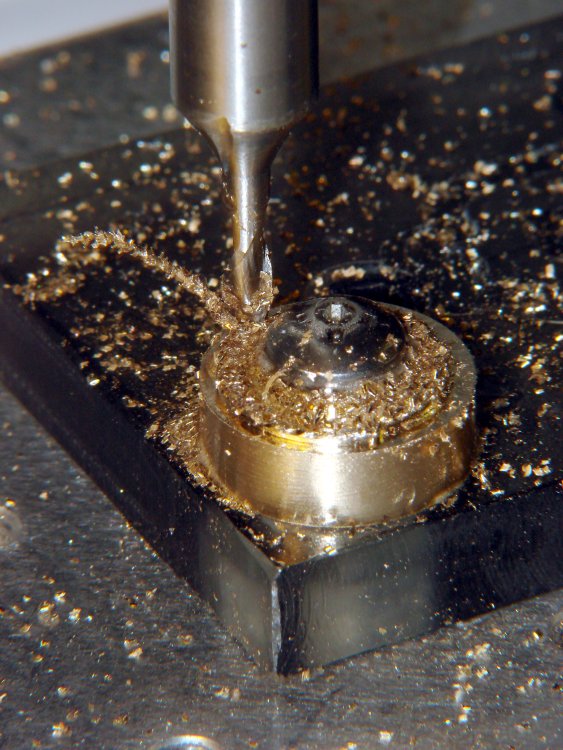
    Then cut out the broken part shown in the first picture. It’s attached to the lens with a U-shaped bit of transparent plastic that fits into the frame holes and captures its two peg legs; I used flush-cutting pliers to carve away the plastic bar on the inside of the lens.

    The lens mount fragment is flat-out not reparable, but the broken end of the earpiece lies flush against the lens and is roughly circular. Even better, a 1/16 inch brass tube from the Little Box o’ Cutoffs fit the temple end perfectly: OD = 62 mils, ID = 35 mils.

    The Little Box o’ Tiny Screws produced a pair of stainless steel screws (intended for the hinges in ordinary eyeglass temples) that also fit the holes in the lens and were precisely the right length, so the overall plan came together. The screws seem a bit over 1 mm diameter and I don’t have a nut for them, but epoxy is my co-pilot…

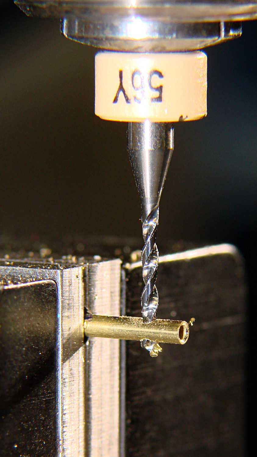
    Line up and drill a pair of 47 mil clearance holes in that piece of 62 mil OD brass tubing, leaving barely 7 mil behind on each side:

    Drilling brass tube
    Drilling brass tube

    I may have to frame that picture…

    Much to my astonishment, drilling those two holes worked on the first try. I’d chamfered the end with a #1 center drill while mulling over how all this would work out.

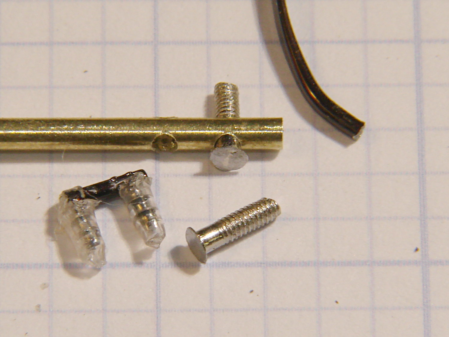
    File off the screw heads to leave a thin plate:

    Silhouette frame - temple mount parts
    Silhouette frame – temple mount parts

    A dry fit shows how everything hangs together:

    Silhouette frame - temple trial fit
    Silhouette frame – temple trial fit

    The intact earpiece holds the lens at the proper angle on a flat surface, so as long as I can keep the repair parts in place on the lens, the temple angle will take care of itself.

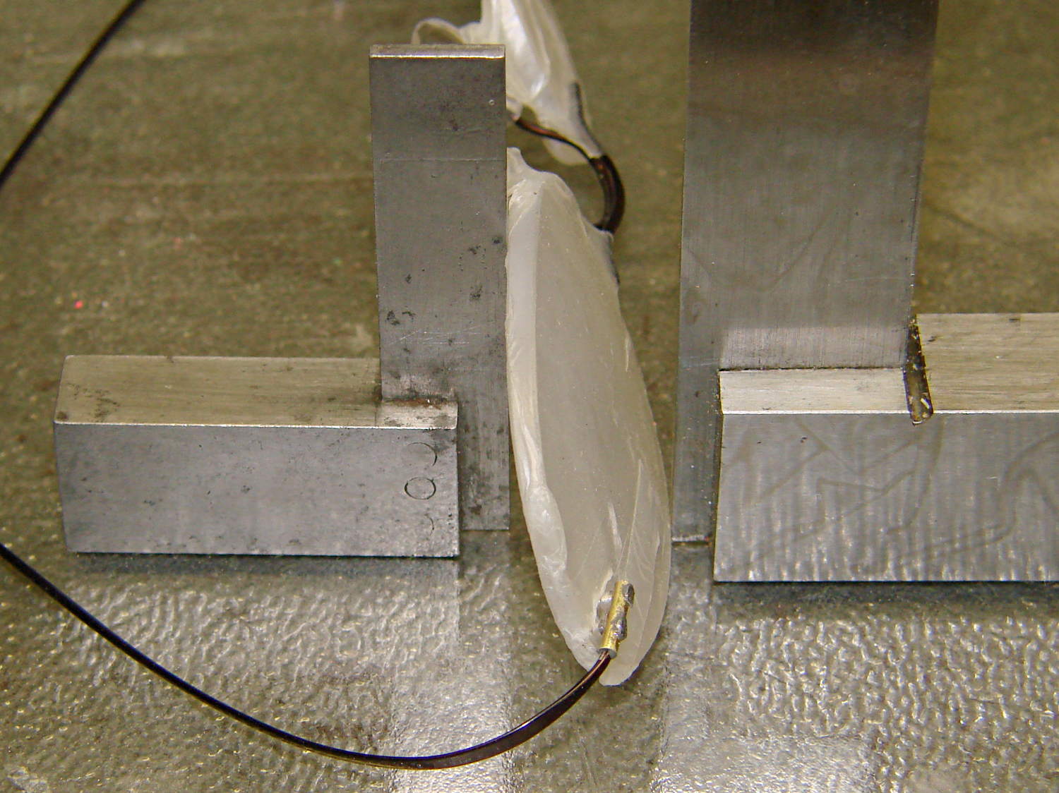
    I scuffed up the broken end of the earpiece to encourage a good epoxy bond, bent the edges of those flat plates around the tube, and cleaned everything with acetone. Tiny dabs of JB Weld epoxy hold the screws and the temple piece in the tube, with those little machinist’s squares encouraging the lenses to stay put:

    Silhouette frame - mount curing
    Silhouette frame – mount curing

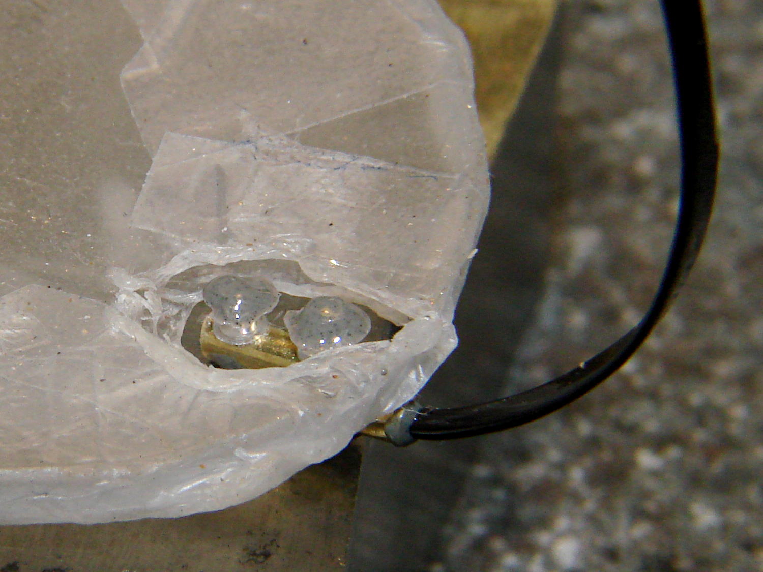
    A day later, lay the lenses face down so the screws point straight up and dab on more JB Weld:

    Silhouette frame - lens mount curing
    Silhouette frame – lens mount curing

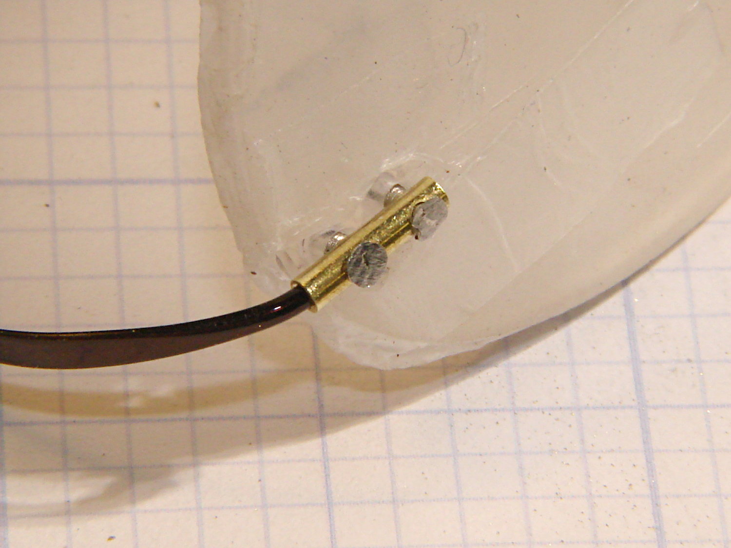
    Those dots aren’t quite as round as I’d like, but they’re the better part of 2 mm OD and I’m not complaining much. Note the nice fillet around the temple piece at end of the tubing.

    Pause another day for curing…

    Then file off the rough edges and peel off the Parafilm. It’s a bit on the garish side, but Mary preferred the Steampunk look over a crude paint job, particularly because it’s invisible from her side of the lens:

    Silhouette frame - repaired
    Silhouette frame – repaired

    There, now, that wasn’t so hard after all…

  • Musings on a Vacuum Table

    After looking at all the holes in the maximum-size PCB platen for the Sherline mill, I started thinking about a vacuum table for things like PCBs and engraved slabs.

    I recently harvested the compressor from a defunct dehumidifier:

    Harvested Dehumidifier Compressor
    Harvested Dehumidifier Compressor

    That ought to be useful in a DIY vacuum table that needs a good, low-volume pump. It seems refrigeration pumps can get down around 29 inches of mercury, so the net pressure difference is maybe 13 psi and I’d round it down to 10 psi. Typical small PCBs, say 1 x 2 inches, would have 20 to 30 pounds of downforce.

    From what I read, the pump will blurp oil from the smaller outlet tube while settling down to pull a vacuum through the larger, rather discolored, inlet tube; adding a larger diameter vertical catch chamber with a splash plate to the outlet would be in order. I think a trash filter on the inlet, perhaps conjured from a defunct whole-house water filter with a 3 micron spun-fiber filter element, should keep dust and crud out of the compressor; the inlet already has a small filter / dryer (the lump next to the compressor body), but that probably won’t withstand an assault of glass-fiber-laden PCB drilling dust.

    As far as the vacuum table goes, I think a 3D printed base with a machinable wax insert might be just the ticket: the base collects all the complexity, including hose fittings and a plenum under the insert, into a 3D model where it’s easy to duplicate and the cheap-and-simple wax acts as a moderately hard sacrificial platform. The base would have 10-32 holes around the outside to match the Sherline’s tooling plate. The wax insert could stand proud of the base and have holes only where they’re needed, so the base holds the insert in place mostly by vacuum.

    You’d (well, I’d) like to cast the wax in place, but it melts around 240 °F = 115 °C and gets pourable around 270 °F = 132 °C, well above the point where PLA gets juicy and about where ABS gets gummy, so I think a drop-in slab makes more sense; cast it on a plate for a flat bottom surface, trim off the mold flash, and drop it in place with the flat side down. Then, with the vacuum turned on, flycut the rumpled top to get a known-flat-and-true surface, mill some vacuum channels, and drill holes to match the 3D printed holes in the plenum; all that would be a G-Code routine, of course. A simple hexagonal drilled pattern (big shallow holes for maximum clamping, little through holes into the plenum) might be a good starting point, at least for the simple, low-stress stuff I’m doing: PCBs and maybe edge-lit ersatz Nixie tubes.

    You could gently heat the part to seal it to the wax, although that might risk losing the top surface alignment. Given reasonably flat PCB material, a custom channel pattern under the board might be just as good.

    When the wax gets sufficiently chopped up that it can’t hold a good seal, toss it in the remelting bin, drop in a new slab, mill it to suit, and continue the mission.

    If you do it right, everything’s parametric and you can generate a custom base with a custom insert by twiddling a few parameters that set the overall size of the thing; print up the base, drop in a wax plate, machine the top surface, done. You’d need two source files: OpenSCAD for the base and custom G-Code for the insert. Maybe the OpenSCAD script can generate and export a DXF-ish file that could produce the mill / drill code for the insert.

  • PCB Drilling Platen: Wear and Tear Thereof

    This PCB will become a brassboard for a blinky light using Hall effect current sensing:

    Hall Current Control LED Blinky - PCB Drilling
    Hall Current Control LED Blinky – PCB Drilling

    Most of the components are in SMD packages, so it’s tough to wire a complete test circuit without making a PCB.

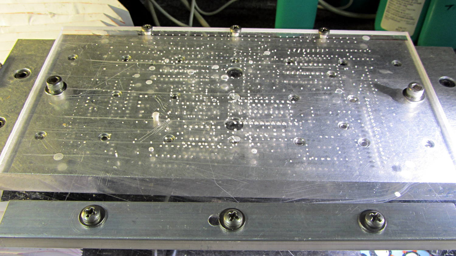
    The maximum-size PCB drill platen is getting chewed up, although it’s nowhere near end-of-life:

     PCB Drilling Platen
    PCB Drilling Platen

    But I’m thinking about a vacuum table…

  • More Header Pin Slitting

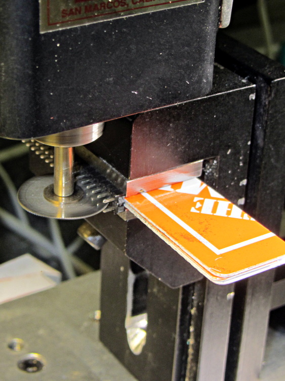
    My stock of single-row header pins seems to be running short, so it’s time for another slitting session:

    Header pin slicing
    Header pin slicing

    Manual CNC, typing bare G-Code directly into LinuxCNC Axis: no reason to turn the cranks by hand.

    This makes absolutely no economic sense, but it’s a sticky-hot day and the Basement Laboratory has the dehumidifier. Some day I’ll run into a killer surplus sale of single-row headers and that’ll solve the problem forever…

  • Edge-Lit Acrylic “Nixie” Display: Doodles

    The Basement Warehouse Wing has an essentially unlimited supply of pristine CD cases (remember CDs?) that, with a bit of deft bandsaw work, will each emit a pair of 4×4 inch sheets of perfectly transparent acrylic plastic. The sheets are about 1.3 mm = 50 mils thick, which is just about exactly what you want for a Nixie-style display that doesn’t require high voltages, because you can edge-light a sheet with 0603 amber SMD LEDs. Obviously, this is not a Shining New Idea, but this post collects my doodles so they don’t get lost along the way.

    The Squidwrench StickerLab session prodded me into lashing a prototype together to see how this would work; they have a Silhouette Cameo vinyl cutter driven with Robotcut that works well. I’d hoped to do some laser cutting at the subsequent session, but our schedules didn’t mesh.

    The compelling advantage of laser cutting is that you could crack the CD cases apart, throw out the CD holder gimcrackery, lay the sheets flat on the cutter table with the latches & other junk upward, and burn the digits out of the middle without any further preparation. I think I could get much the same effect, at least for a crude prototype, by milling & engraving with the Sherline.

    The sheets are about 4 threads of 3D printed plastic extruded at the M2’s default 0.4 mm width. You could print a black baseplate with slots to hold the sheets, put two threads between each sheet, and have the sheet 6 threads apart on center = 2.4 mm spacing:

    Tab vs 3D thread size doodle
    Tab vs 3D thread size doodle

    Ten such sheets would produce a standard 0-to-9 display about an inch deep, plus protective sheets front and back, so the whole affair would be maybe 1.25 inch deep. You’d probably want to offset the tabs on adjacent sheets to reduce light leakage between LEDs. The baseplate fits atop a PCB with LEDs at the right locations, so you get an opaque holder for the sheets that’s easy to produce and easy to assemble:

    Sheet tab layout doodle
    Sheet tab layout doodle

    If you were clever, you could have different tab locations on each sheet so they’d fit only in the proper orientation; that might be important for cough mass production.

    The M2 has a platform big enough to build an entire clock base in one pass, plus a matching piece to capture the tops of the digits. I think edge-lit acrylic needs a complete opaque surround for each digit sheet to block light leaking from the edges; it might be easier to build the mount in the other direction, lying flat on the platform, stack the mounts together with the digit sheets, then bolt the whole assembly from the front; that would ensure perfect alignment of everything.

    In that case, the 3D printed layers are 0.25 mm (or smaller), but the resolution for the tabs would be 0.4 mm. If you were exceedingly brave & daring, you could lay the digit sheets in place during the build and come out with a monolithic unit; that might require a bit of clearance atop each sheet, as a grazing touch from a hot nozzle would be painfully obvious.

    There’s no reason you couldn’t have 16 sheets for a hexadecimal display; this would work out nicely with 8-bit shift registers using SPI from the usual Arduino-love controller. One might prefer current-limiting LED drivers.

    There’s also no reason you couldn’t use a wider “digit” sheet and engrave, say, the days of the week or the units of measurement or something like that on each panel.

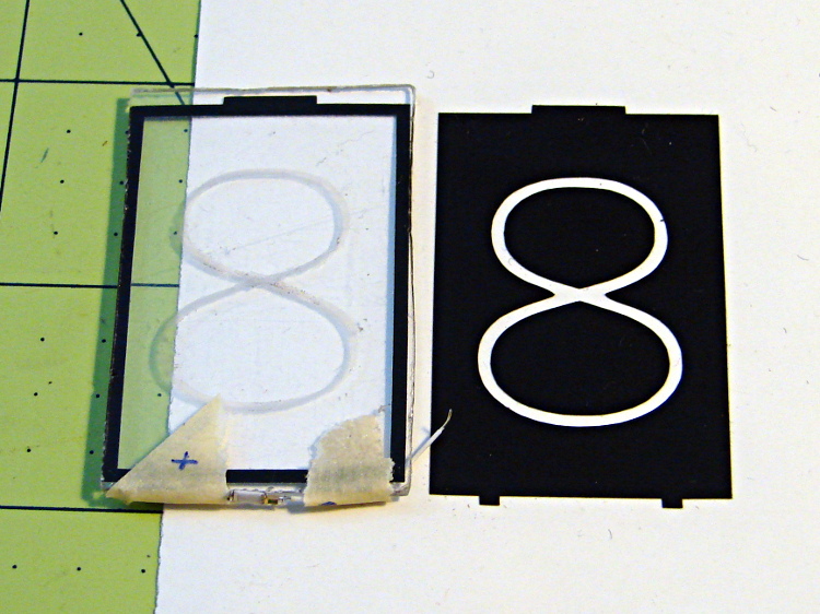
    If the display will be 30 mm deep, then the digits must be large enough that the depth doesn’t turn each digit into a tunnel. Large Nixe tubes had digits about 40 mm tall, so I went with a 30 x 45 panel, plus 1 mm tabs on the top and bottom:

    Crude edge-lit acrylic panel vs vinyl stencil
    Crude edge-lit acrylic panel vs vinyl stencil

    The “engraved” digit on the left came from a vinyl mask similar to the one on the right, using fine sandpaper to rough up the acrylic surface. I deliberately started with a battered old CD case in order to prevent myself from getting too compulsive with neatness; as you’ll see, edge-lit acrylic reveals any surface imperfections, so cleanliness is important.

    The black border could be a light-shield gasket around the outer edge of the display panel to reduce glare from the edges. This might be more important for laser-cut pieces with highly reflective edges or for milled pieces with diffuse edges; there’s no way to tell without actually building one to see. I simply bandsawed the sheet around the edges of the mask, then filed off the larger chunks: the edges are very, very rough, indeed.

    There doesn’t seem to be an easy way to stash the Inkscape SVG file on WordPress.

    I solder-blobbed some wire-wrap wire, a 1206 SMD resistor, and a 0603 LED together:

    Crude 0603 SMD LED lashup
    Crude 0603 SMD LED lashup

    The 0603 SMD LED fits neatly along the edge of the sheet:

    0603 SMD on CD case edge
    0603 SMD on CD case edge

    A 3rd hand holds it upright on the bench over the LED lashup:

    Edge-lit acrylic - front layout
    Edge-lit acrylic – front layout

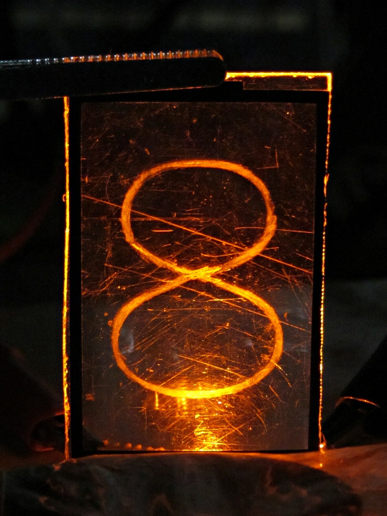
    It looks marginally better with the lights out, but you can see all the scratches:

    Edge-lit acrylic - front detail
    Edge-lit acrylic – front detail

    The hot spot at the bottom of the digit isn’t nearly that awful in person.

    A top view shows the glowing edges, plus the nuclear glow from the LED:

    Edge-lit acrylic - top view
    Edge-lit acrylic – top view

    A touch of soft focus, plus moving the LED under a tab location, helps a bit:

    Edge-lit acrylic - front soft focus
    Edge-lit acrylic – front soft focus

    You’d want two LEDs per digit and maybe one at the top, but that’s in the nature of fine tuning.

    All in all, I like how it looks. Getting from this crud to a workable display will require far more effort than I can devote to it right now…

  • Storm Door Latch: Repair Parts

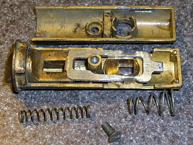
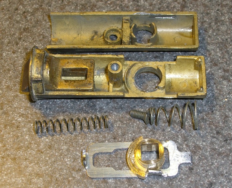
    The discussion following that post on getting feature coordinates from an existing part reminded me of an old project that I’d written up for Digital Machinist: making repair parts for the half-century old storm doors on our house. Here’s the whole latch, with a replacement drawbar and cam:

    Latch Assembly
    Latch Assembly

    The other side of the drawbar and cam:

    Door Latch Parts
    Door Latch Parts

    An early version of the drawbar that engages the latch strike and gets pulled by cam:

    New and Old latch pulls
    New and Old latch pulls

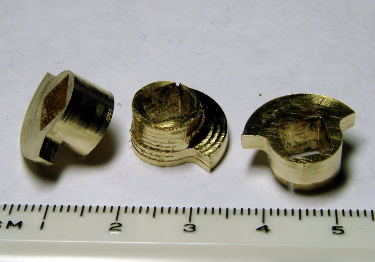
    Three iterations on a cam; the messed-up one in the center, IIRC, helped track down an EMC2 bug:

    Latch Cams
    Latch Cams

    Now that I look at it again, there’s nowhere near enough meat around that square hole for a 3D printed plastic part… so the notion of printing the complex part of the cam and adding wear bars along those ears just isn’t going to work.

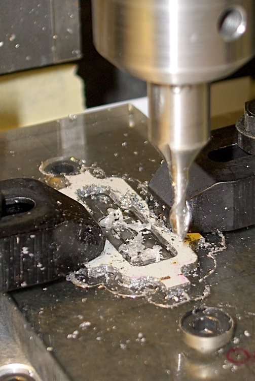
    I made a fixture for the Sherline CNC mill to hold the drawbar for inside milling:

    Latch pull - Inside milling
    Latch pull – Inside milling

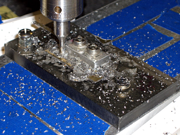
    Then a block screwed down in the middle clamps the drawbar in the same place for outside milling:

    Latch pull - Outside milling
    Latch pull – Outside milling

    The square post in the left rear corner holds the cam:

    Latch Cam - First Attempt
    Latch Cam – First Attempt

    Note that I had to file the square hole before milling the cam shape, which meant that if the CNC process screwed up, all that handwork went into the show-n-tell bin… which I’m not going to show you.

    I used an early version of the grid-overlay technique to map out the drawbar coordinates; this was an illustration for the column:

    Latch Pull Dimensions
    Latch Pull Dimensions
  • CNC Platform Corner Clip Fixture

    This is a classic case of investing more time and effort creating the fixture than machining the parts.

    Start by squaring up the block, which came from the end of a random chunk of smoke gray polycarbonate, with two 10-32 holes matching the tooling plate hole spacing:

    Corner Clip Fixture - squaring
    Corner Clip Fixture – squaring

    Then drill-and-tap four holes:

    Corner Clip Fixture - tapping
    Corner Clip Fixture – tapping

    The left station will be for drilling the blanks clamped under a sacrificial sheet, so those screw holes aren’t used for anything other than clearance; the top millimeter will get chewed up pretty quickly. The screws in the right station will clamp a stack of drilled blanks under a cover plate. If I went into production, I could see using both stations for both functions, but …

    There’s a locating pip in the front left corner that works perfectly with laser alignment:

    Corner Clip Fixture - aligning
    Corner Clip Fixture – aligning

    The blank sheets show where they’d be located for drilling, minus the sacrificial sheet and its clamps that you’ll see below.

    The G54 coordinate system origin sits at the locating pip. The G-Code then slaps a G55 origin at each of the two stations in turn to simplify their coordinates, with offsets from M54:

    • Drilling = (+5,+5)
    • Milling = (+40,+5)

    With all that in hand: stack, clamp, and drill some blanks:

    Corner Clip Fixture - drilling
    Corner Clip Fixture – drilling

    I tried milling a single drilled blank with a sacrificial plastic top plate:

    Corner Clip Fixture - first milling setup
    Corner Clip Fixture – first milling setup

    But that didn’t work well. I don’t know if this was due to an inept combination of climb milling, using the wrong speed / feed / material / cutter, and just poor style, but the edges of the blank mashed against the clamp plate and curled, instead of cutting cleanly:

    Corner Clip Fixture - rounded-over milled edges
    Corner Clip Fixture – rounded-over milled edges

    So I made a pair of aluminum plates to clamp both sides of the blanks, then milled another stack:

    M2 platform clips - milling edges
    M2 platform clips – milling edgesM2 platform clips – milling edges

    That worked quite well, although the top and bottom clips needed some slight attention from a riffler file and I did break the edges on all the clips. This shows four new clips along with a hand-cut prototype:

    Corner Clip Fixture - end result
    Corner Clip Fixture – end result

    So I made a dozen more clips, picked the best eight for two sets, sent one set to Dan, installed the other, and … now I have a bunch of spares.

    I suppose I should sell clip sets on Etsy / eBay to all the other M2 owners, but I have no idea how to price ’em. If you want some fancy corner clips, send whatever you think they’re worth … [grin]