The Basement Warehouse Wing has an essentially unlimited supply of pristine CD cases (remember CDs?) that, with a bit of deft bandsaw work, will each emit a pair of 4×4 inch sheets of perfectly transparent acrylic plastic. The sheets are about 1.3 mm = 50 mils thick, which is just about exactly what you want for a Nixie-style display that doesn’t require high voltages, because you can edge-light a sheet with 0603 amber SMD LEDs. Obviously, this is not a Shining New Idea, but this post collects my doodles so they don’t get lost along the way.
The Squidwrench StickerLab session prodded me into lashing a prototype together to see how this would work; they have a Silhouette Cameo vinyl cutter driven with Robotcut that works well. I’d hoped to do some laser cutting at the subsequent session, but our schedules didn’t mesh.
The compelling advantage of laser cutting is that you could crack the CD cases apart, throw out the CD holder gimcrackery, lay the sheets flat on the cutter table with the latches & other junk upward, and burn the digits out of the middle without any further preparation. I think I could get much the same effect, at least for a crude prototype, by milling & engraving with the Sherline.
The sheets are about 4 threads of 3D printed plastic extruded at the M2’s default 0.4 mm width. You could print a black baseplate with slots to hold the sheets, put two threads between each sheet, and have the sheet 6 threads apart on center = 2.4 mm spacing:

Ten such sheets would produce a standard 0-to-9 display about an inch deep, plus protective sheets front and back, so the whole affair would be maybe 1.25 inch deep. You’d probably want to offset the tabs on adjacent sheets to reduce light leakage between LEDs. The baseplate fits atop a PCB with LEDs at the right locations, so you get an opaque holder for the sheets that’s easy to produce and easy to assemble:

If you were clever, you could have different tab locations on each sheet so they’d fit only in the proper orientation; that might be important for cough mass production.
The M2 has a platform big enough to build an entire clock base in one pass, plus a matching piece to capture the tops of the digits. I think edge-lit acrylic needs a complete opaque surround for each digit sheet to block light leaking from the edges; it might be easier to build the mount in the other direction, lying flat on the platform, stack the mounts together with the digit sheets, then bolt the whole assembly from the front; that would ensure perfect alignment of everything.
In that case, the 3D printed layers are 0.25 mm (or smaller), but the resolution for the tabs would be 0.4 mm. If you were exceedingly brave & daring, you could lay the digit sheets in place during the build and come out with a monolithic unit; that might require a bit of clearance atop each sheet, as a grazing touch from a hot nozzle would be painfully obvious.
There’s no reason you couldn’t have 16 sheets for a hexadecimal display; this would work out nicely with 8-bit shift registers using SPI from the usual Arduino-love controller. One might prefer current-limiting LED drivers.
There’s also no reason you couldn’t use a wider “digit” sheet and engrave, say, the days of the week or the units of measurement or something like that on each panel.
If the display will be 30 mm deep, then the digits must be large enough that the depth doesn’t turn each digit into a tunnel. Large Nixe tubes had digits about 40 mm tall, so I went with a 30 x 45 panel, plus 1 mm tabs on the top and bottom:
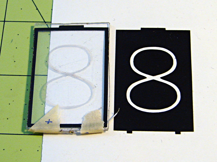
The “engraved” digit on the left came from a vinyl mask similar to the one on the right, using fine sandpaper to rough up the acrylic surface. I deliberately started with a battered old CD case in order to prevent myself from getting too compulsive with neatness; as you’ll see, edge-lit acrylic reveals any surface imperfections, so cleanliness is important.
The black border could be a light-shield gasket around the outer edge of the display panel to reduce glare from the edges. This might be more important for laser-cut pieces with highly reflective edges or for milled pieces with diffuse edges; there’s no way to tell without actually building one to see. I simply bandsawed the sheet around the edges of the mask, then filed off the larger chunks: the edges are very, very rough, indeed.
There doesn’t seem to be an easy way to stash the Inkscape SVG file on WordPress.
I solder-blobbed some wire-wrap wire, a 1206 SMD resistor, and a 0603 LED together:

The 0603 SMD LED fits neatly along the edge of the sheet:

A 3rd hand holds it upright on the bench over the LED lashup:

It looks marginally better with the lights out, but you can see all the scratches:
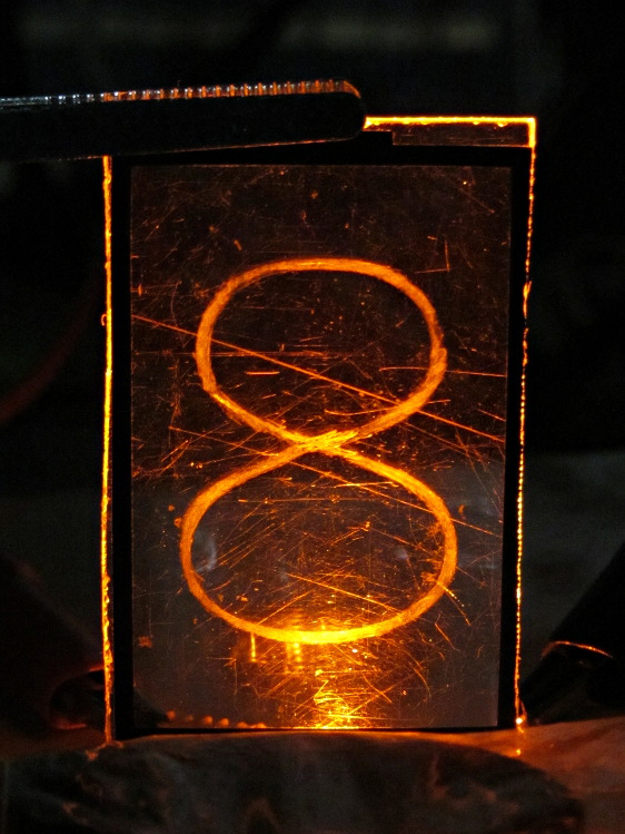
The hot spot at the bottom of the digit isn’t nearly that awful in person.
A top view shows the glowing edges, plus the nuclear glow from the LED:
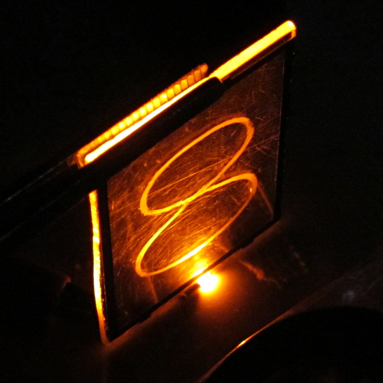
A touch of soft focus, plus moving the LED under a tab location, helps a bit:

You’d want two LEDs per digit and maybe one at the top, but that’s in the nature of fine tuning.
All in all, I like how it looks. Getting from this crud to a workable display will require far more effort than I can devote to it right now…

Comments
8 responses to “Edge-Lit Acrylic “Nixie” Display: Doodles”
Would sanding the bottom, or using a thin piece of rice paper or say a translucent milk bottle on the bottom edge work as a diffuser, spreading the light more evenly at the slight expense of brightness work effectively you think ?
The little tabs on the bottom serve as both positioning features and light pipes, with an LED directly below each one. A clear finish (laser or maybe solvent) on the tab ends would get more light into the slab, but I don’t know if that would produce a hot spot on that side of the digit. The matte finish left by a milling cutter would certainly diffuse the light, although it’s still starting out from essentially a point source and I don’t know how it would look.
That bandsaw finish definitely isn’t in the running… [grin]
The next step is some G-Code to carve a slab out of an acrylic sheet, complete with tabs, then engrave a digit in the middle. I think I can do that in one setup, even without the long-awaited and much-anticipated vacuum table; it worked OK for the dog tags, anyway. With some digit slabs in hand, I can mock up a better prototype and play with surface finish.
Rice paper. Huh. Perhaps our Larval Engineer left something like that in her pile o’ artsy stuff…
Fond memories of Nixies–we used to use Fairchild 5000C testers at HP until the mid-90s (heresy not to use HP equipment, but they were fast and dirt cheap for the jelly bean parts we built), and the control panels used Nixies. Eventually, they got replaced with S3* displays, but the tubes (12AT7 type package) were a nice touch. Felt like a set from Failsafe or a tech movie from the ’60s.
* S3, the real reason for the post… Stretched Seven Segment. The LED was at the apex of a triangle of clear plastic, and the light was spread evenly by the geometry. Might be worth exploring if uniformity is an issue.
I think I can machine a triangle… [grin]
Maybe the trick is to give each tab the proper geometry to reflect the LED’s light cone across the bottom of the digit. Next stop: ray tracing through the LED-to-tab interface, keeping in mind acrylic’s index of refraction. Can I complexicate it any more than that? [wince]
You may need to figure out the light pattern for the LEDs you are using. The ancient packages that HP did had a reflector cone in them, because the die put more light out the sides than straight up. One would hope the SMD packages have the light coming out the top, but best to get a rough idea. Shoot, just stick a bit of paper near the lit device and see where the cone points.
Not sure you need to worry about ray tracing. A SWAG should get you there.
Oh, no, this is the age of science! [grin]
One thing for sure: don’t expect a neat Gaussian distribution…
Hmm, sort of consistent with the cone reflector arrangement used at HP with a good amount of light from the top. The core of the light cone looks like it could be Gaussian, but with the light from the periphery getting focussed as a cone. That would be a three-pipe problem if I still smoked. [grin]
[…] a good starting point, at least for the simple, low-stress stuff I’m doing: PCBs and maybe edge-lit ersatz Nixie tubes. […]