Ed Nisley's Blog: Shop notes, electronics, firmware, machinery, 3D printing, laser cuttery, and curiosities. Contents: 100% human thinking, 0% AI slop.
For some unknown reason, one of the very rare updates to the Ubuntu 10.04 LTS infrastructure (for LinuxCNC 2.5.3 on my Foxconn D510 box, driving the Sherline mill) stopped supporting the system board’s built-in NIC: networking stopped working. The only symptom was that the NIC didn’t respond and all the usual tricks were unproductive.
After some fruitless searching, I took the easy way out:
NIC added to Foxconn D510 PC
That’s the backside of an ancient NIC using the classic Tulip driver. It used to have a full-size bracket, which I chopped off, bent, and filed to suit, much as with that one in the D525.
Fired it up, the kernel automagically picked the proper driver, and networking Just Worked again.
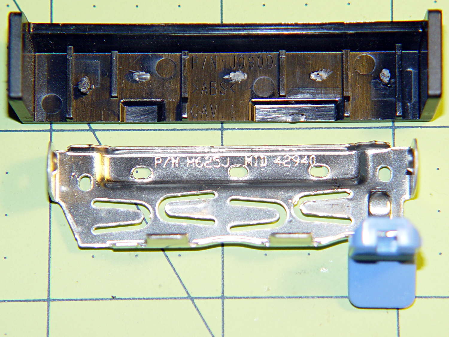
The new-to-me Optiplex 980 has a tool-free clamp securing the PCI card brackets to the chassis, with a nice plastic dress cover that really finishes off that side of the case. Alas, it’s secured by five small heat-staked plastic pegs that I managed to shear off as part of a finger fumble that you’ll recognize when it happens to you and which I need not further discuss:
Optiplex 980 PCI Clamp Cover – disassembled
So I drilled two slightly undersized holes for the tiniest screws in the Little Box o’ Tiny Screws:
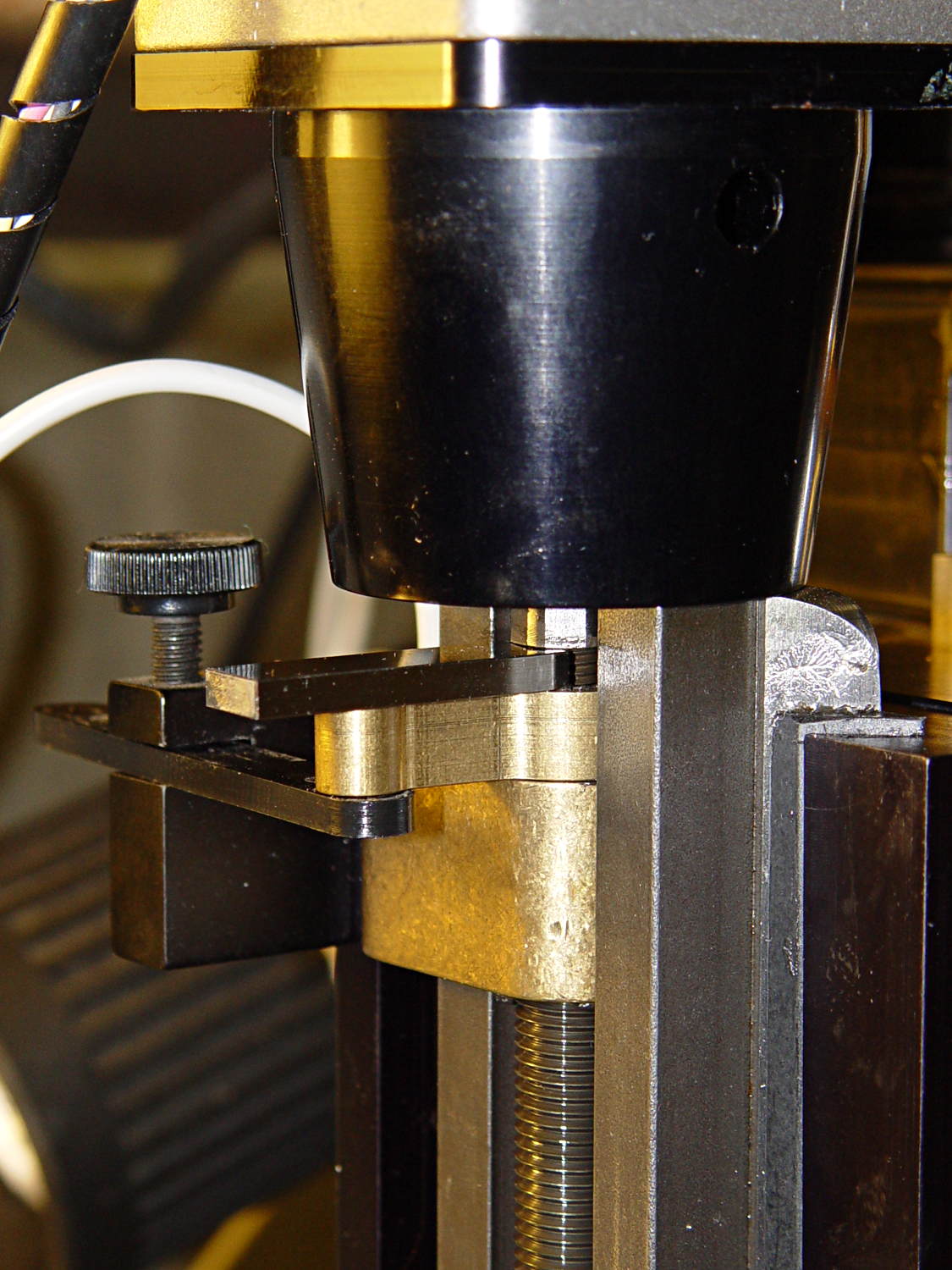
Optiplex 980 PCI Clamp Cover – drilling
The two end plates sticking up are the only square parts of the cover, so that thing is actually clamped by the right-side plate and sheer will power. I ran the drill down 3 mm from the top of the post at the slowest manual jog speed from the Joggy Thing and I did not break through the top and did not hit that lathe bit under the cover.
The screw threads and a dab of epoxy hold them in place:
Optiplex 980 PCI Clamp Cover – tiny screws
I’d like to say the finished repair looked like this:
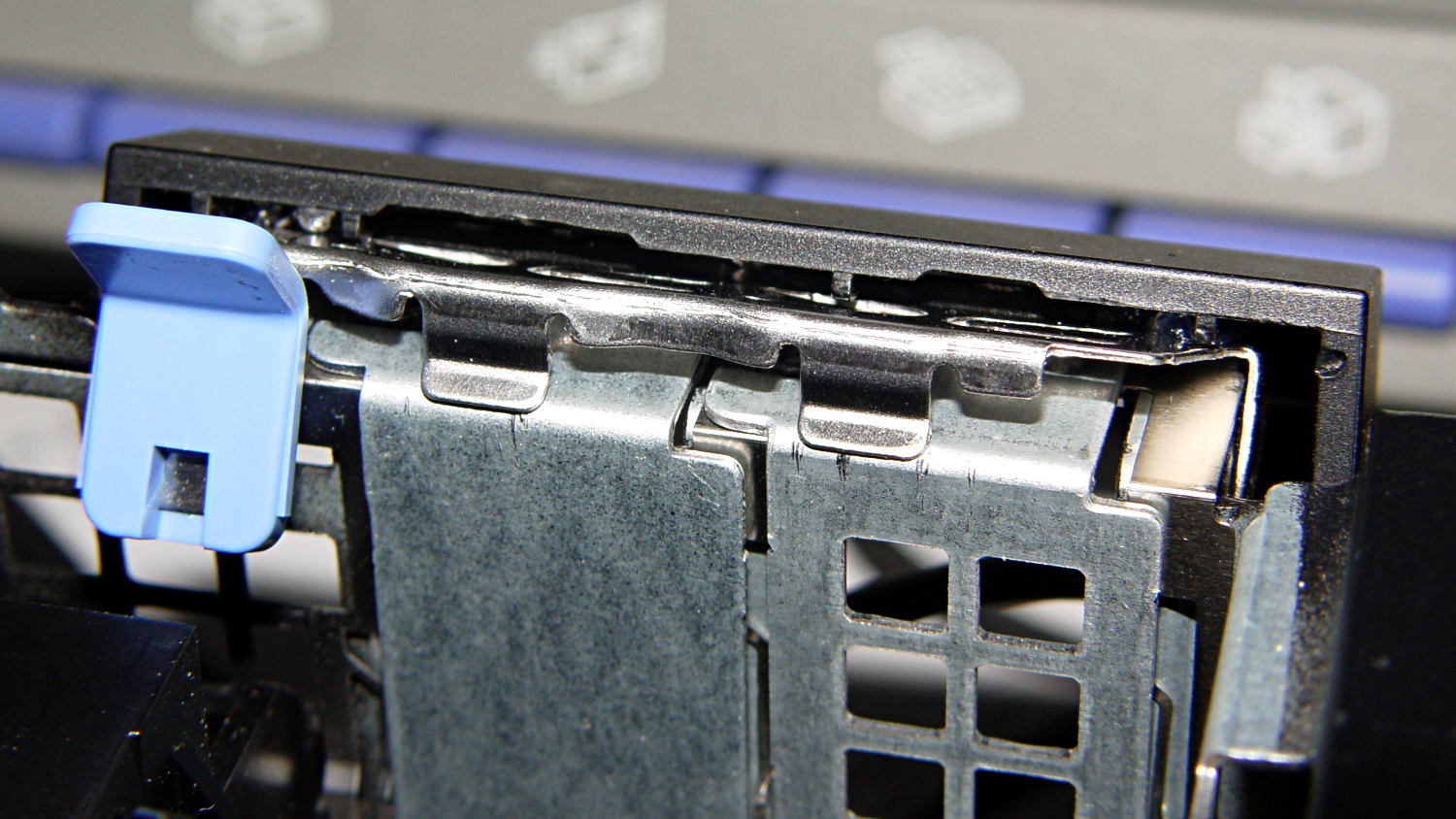
Optiplex 980 PCI Clamp Cover – in place
But, alas, the eagle-eyed reader will note that the screws are gone, replaced by two dabs of clear acrylic caulk; those faint threads and epoxy were no match for the snap of that latching lever and the slight distortion caused by the spring fingers applying force to the brackets.
Turns out that it’s 0.1340 inches, determined by bracketing the sliver above that 0.1300 block with feeler gauges. I don’t believe that last zero, either, as the Basement Shop was about 10 °F below the block’s 68 °F calibration temperature. [grin]
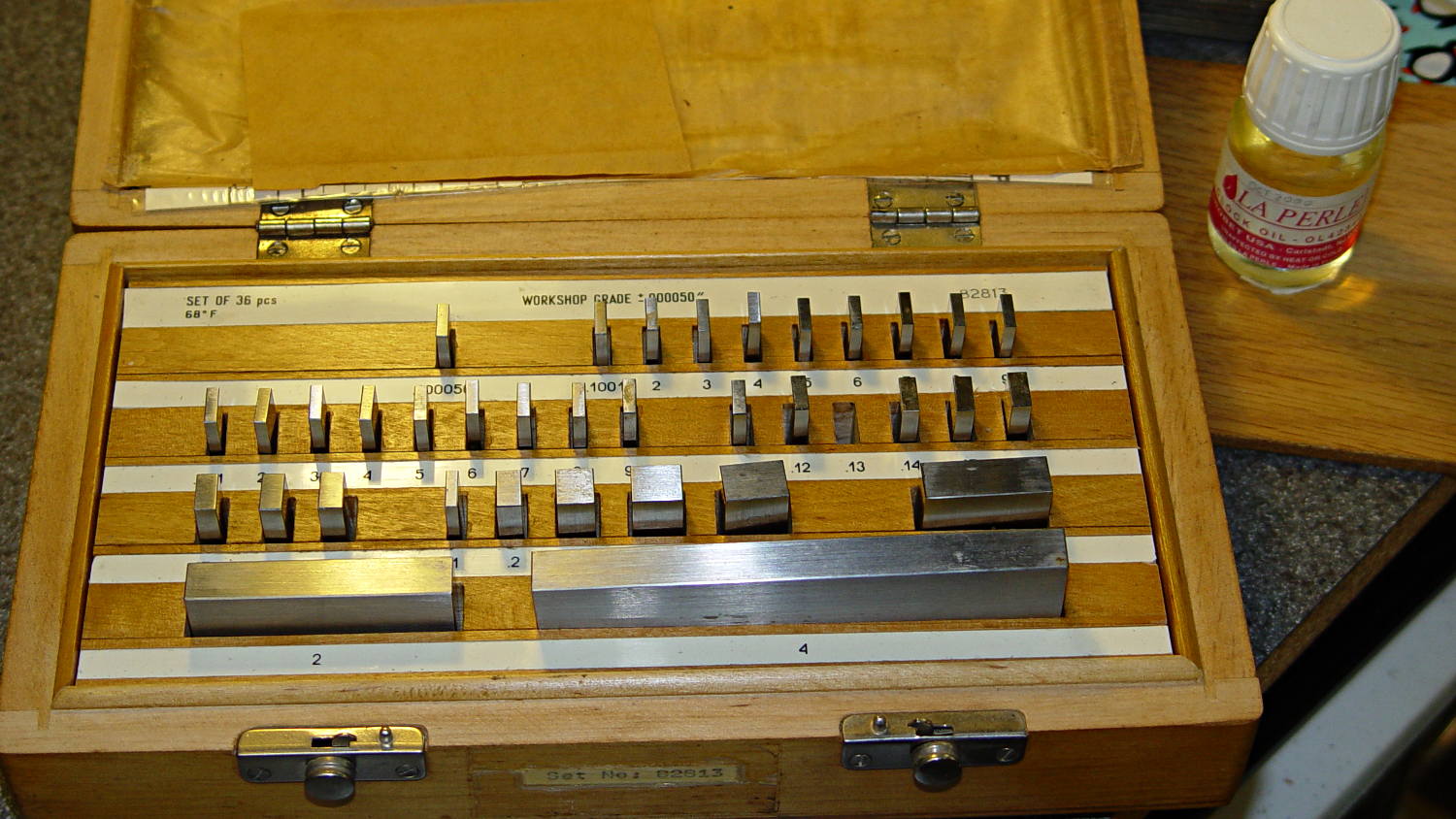
The actual size of that gap makes absolutely no difference whatsoever, but fooling around with the gauge blocks gave me an excuse to renew my acquaintance with them and, en passant, massage some oil over their long-neglected bodies:
Gauge block set
I used La Perle Clock Oil, which isn’t Official Gauge Block Oil, but doesn’t go bad on the shelf. Verily, this bottle may be the last of its kind, as it’s no longer available from any of the usual sources; it appears I bought it back in 2000.
The blocks are in good shape, probably because they don’t often see the light. FWIW, I have experimentally determined that my body oil doesn’t etch fingerprints into steel.
The block set, which is similar to a current box o’ blocks from Enco, claims “Workshop Grade”, but the ±0.00050 inch = 1.27 μm tolerance shown in the top row of the labels is much worse than even grade B’s sub-micron tolerance. That newer box claims “Economy” accuracy with the same spec, so I suppose somebody kvetched about mis-using the terms.
Ah, well, they’re far better than any measurements I’ve needed in a while and entirely suitable for verifying my other instruments.
Turns out that I managed to crunch it, exactly as I expected: I’d added a block to the Z-axis stage that poked the home switch just slightly before the anti-backlash nut unscrewed from the top of the leadscrew, but the stage could continue moving another few millimeters.
You can see the gap just above the brass anti-backlash nut:
Sherline Z-axis leadscrew nut – top end
At that point, the nut has barely a single micro-smidgen of thread engaged; that last 0.1340 inch of travel (yeah, I measured it) isn’t usable.
Rather than put a collar around the end of the leadscrew, I opted for a brute-force block atop the Z-axis saddle nut that will slam into the bottom of the stepper motor mount just before the anti-backlash nut disengages:
Sherline Z-axis Overrun Block – rear view
A strip of tapeless sticky (double-sided tape, minus the tape) holds the block in place on the saddle nut. It’s not subject to any particular stress: as long as it doesn’t fall off, it’s all good.
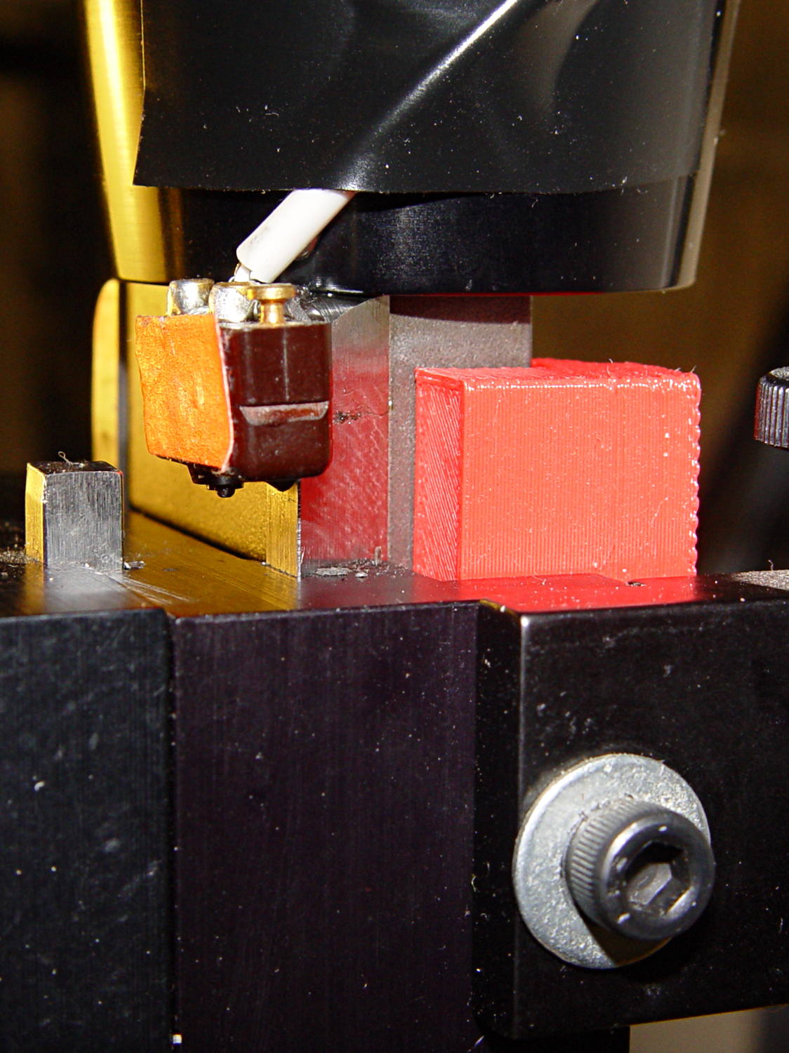
I ran the stage upward until it stalled, then epoxied a new switch (with the old fluorescent tape) in place. This shows the result after backing the stage down a few millimeters:
Sherline Z-axis Overrun Block – side view
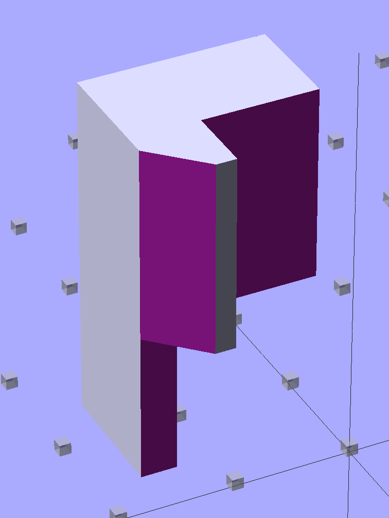
The solid model shows off the bevel that provides a bit more room for anti-backlash nut adjustment, not that I ever adjust it that much:
Sherline Z-Axis Overrun Prevention Block – solid model
Obviously, it doesn’t print in that position, but it’s easier to design it in the natural orientation and flip it around for printing.
The OpenSCAD source code:
// Sherline Z-axis Overrun Prevention Block
// Ed Nisley KE4ZNU December 2013

Layout = "Show";			// Show Build

//- Extrusion parameters must match reality!
//  Print with 2 shells and 3 solid layers

ThreadThick = 0.25;
ThreadWidth = 0.40;

HoleWindage = 0.2;

Protrusion = 0.1;			// make holes end cleanly

//----------------------
// Dimensions

BlockZ = 30.0;				// overall height
ZLimit = 17.0;				// Z travel limit

TongueX = 9.0;				// beside Z axis dovetail
TongueY = 10.0;

StubX = 6.0;				// behind Z axis pillar
StubY = 3.0;

BlockX = TongueX + StubX;	// overall X

TabY = 3.0;					// behind brass bracket
TabX = BlockX - sqrt(2)*TabY;
TabZ = BlockZ - ZLimit;

BlockY = TongueY + StubY + TabY;	// overall Y

//----------------------
// Useful routines

module ShowPegGrid(Space = 10.0,Size = 1.0) {

  Range = floor(50 / Space);

	for (x=[-Range:Range])
	  for (y=[-Range:Range])
		translate([x*Space,y*Space,Size/2])
		  %cube(Size,center=true);

}

//- The Block

module Block() {

	difference() {
		cube([BlockX,BlockY,BlockZ]);

		translate([-Protrusion,-Protrusion,-Protrusion])	// remove column
			cube([(StubX + Protrusion),(TongueY + Protrusion),2*BlockZ]);

		translate([-BlockX/2,-Protrusion,-Protrusion])		// form tab
			cube([2*BlockX,(TongueY + StubY),(TabZ + Protrusion)]);

		translate([0,BlockY,(BlockZ/2 - 0*Protrusion)])
			rotate(45)
				cube([3*StubY,2*StubY,(BlockZ + 2*Protrusion)],center=true);

		translate([0,0,-Protrusion])
			cube([sqrt(2)*TabY,2*BlockY,(TabZ + Protrusion)]);
	}
}

//-------------------
// Build it...

ShowPegGrid();

if (Layout == "Show")
	Block();

if (Layout == "Build")
	translate([-BlockZ/2,-BlockY/2,BlockX])
	rotate([0,90,0])
		Block();
While putting the speed wrenches in the box with the Sherline four-jaw chuck, it occurred to me that I had all the makings of a handle for Sherline’s steel tommy bars:
Sherline Tommy Bar Handle – solid model
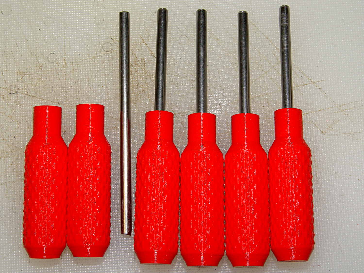
Because these are intended for pushing, rather than twisting, I dialed the knurl back to 32 DP, reduced the depth to 0.5 mm, and ran the bar almost all the way through the handle for strength:
Sherline Tommy Bar Handles
A dab of urethane adhesive inside the handle holds the bar in place. They started out a snug slip fit, so we’ll see how well that holds the bars in place.
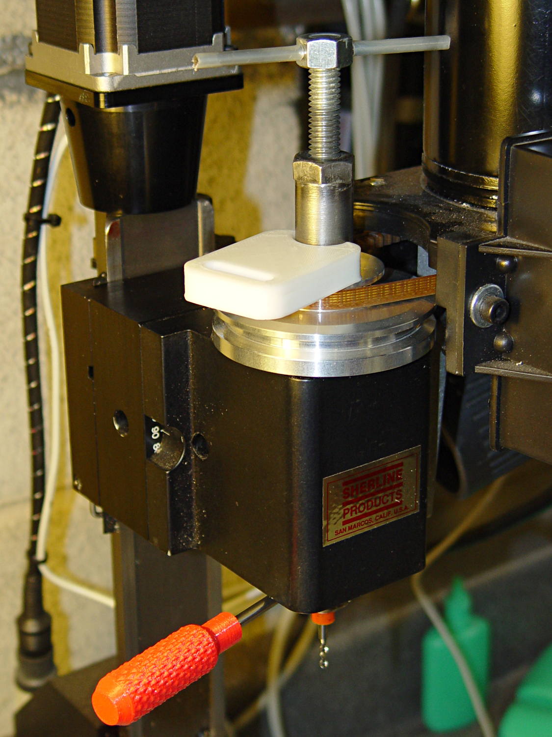
A tommy bar holds the spindle against the torque from the collet pusher:
Sherline CNC mill – tommy bar and collet pusher
A pair will come in handy with the three-jaw chuck the next time that one appears.
The white slab is a very early 3D printed tool from my Thing-O-Matic, made to hold the pin at exactly the proper distance from the pulley so it fits squarely into the pusher and locks it to the spindle:
Locking pin holder – spindle end view
Other folks make much nicer tommy bar handles than mine, but I’d say my 3D printed handles beat a common nail any day!
The OpenSCAD source code:
// Knurled handles for Sherline tommy bars
// Ed Nisley - KE4ZNU - December 2013

use <knurledFinishLib_v2.scad>

//- Extrusion parameters must match reality!
//  Print with 2 shells and 3 solid layers

ThreadThick = 0.20;
ThreadWidth = 0.40;

HoleWindage = 0.2;			// extra clearance

Protrusion = 0.1;			// make holes end cleanly

PI = 3.14159265358979;
inch = 25.4;

//----------------------
// Dimensions

ShaftDia = 10.0;				// un-knurled section diameter
ShaftLength = 10.0;				//  ... length

SocketDia = 4.0;				// tommy bar diameter
SocketDepth = 40.0;

KnurlLen = 35.0;				// length of knurled section
KnurlDia = 15.0;				//   ... diameter
KnurlDPNom = 32;				// Nominal diametral pitch = (# diamonds) / (OD inches)

DiamondDepth = 0.5;				//   ... depth of diamonds
DiamondAspect = 2;				// length to width ratio

NumDiamonds = floor(KnurlDPNom * KnurlDia / inch);
echo(str("Num diamonds: ",NumDiamonds));

NumSides = 4*(NumDiamonds - 1);		// 4 facets per diamond. Library computes diamonds separately!

KnurlDP = NumDiamonds / (KnurlDia / inch);				// actual DP
echo(str("DP Nom: ",KnurlDPNom," actual: ",KnurlDP));

DiamondWidth = (KnurlDia * PI) / NumDiamonds;

DiamondLenNom = DiamondAspect * DiamondWidth;					// nominal diamond length
DiamondLength = KnurlLen / round(KnurlLen/DiamondLenNom);		//  ... actual

TaperLength = 0.75*DiamondLength;

//----------------------
// Useful routines

module PolyCyl(Dia,Height,ForceSides=0) {			// based on nophead's polyholes

  Sides = (ForceSides != 0) ? ForceSides : (ceil(Dia) + 2);

  FixDia = Dia / cos(180/Sides);

  cylinder(r=(FixDia + HoleWindage)/2,
           h=Height,
           $fn=Sides);
}

module ShowPegGrid(Space = 10.0,Size = 1.0) {

  Range = floor(50 / Space);

	for (x=[-Range:Range])
	  for (y=[-Range:Range])
		translate([x*Space,y*Space,Size/2])
		  %cube(Size,center=true);
}

//- Build it

ShowPegGrid();

difference() {
	union() {
		render(convexity=10)
		translate([0,0,TaperLength])
			knurl(k_cyl_hg=KnurlLen,
				  k_cyl_od=KnurlDia,
				  knurl_wd=DiamondWidth,
				  knurl_hg=DiamondLength,
				  knurl_dp=DiamondDepth,
				  e_smooth=DiamondLength/2);
		color("Orange")
		cylinder(r1=ShaftDia/2,
					r2=(KnurlDia - DiamondDepth)/2,
					h=(TaperLength + Protrusion),
					$fn=NumSides);
		color("Orange")
		translate([0,0,(TaperLength + KnurlLen - Protrusion)])
			cylinder(r2=ShaftDia/2,
					r1=(KnurlDia - DiamondDepth)/2,
					h=(TaperLength + Protrusion),
					$fn=NumSides);
		color("Moccasin")
		translate([0,0,(2*TaperLength + KnurlLen - Protrusion)])
			cylinder(r=ShaftDia/2,h=(ShaftLength + Protrusion),$fn=NumSides);

	}
	translate([0,0,(2*TaperLength + KnurlLen + ShaftLength - SocketDepth + Protrusion)])
		PolyCyl(SocketDia,(SocketDepth + Protrusion),6);
}
A Home Shop Machinist article (A Speed Key for Your Four-Jaw Chuck, p 67 Nov-Dec 2013, David Morrow) showed some lovely knurled steel knobs. These 3D printed knobs aren’t nearly as pretty, but they do much the same thing:
Sherline Knobs – in 4 jaw chuck
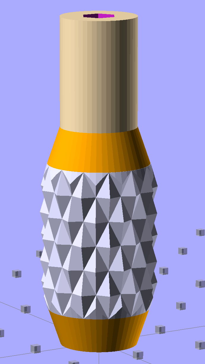
The solid model resembles the illegitimate offspring of a wine bottle and a pineapple:
Sherline Knob – solid model
The knurling comes from aubenc’s Knurled Surface Library v2. I ran off a prototype (on the left), then tweaked the dimensions to get the final version on the right:
Sherline Knobs – knurl depth variation
Being that type of guy, I define the knurl in terms of its diametral pitch, compute the diamond width & length to fit in the available space, then hand those measurements to the knurling library… which recomputes everything and decides on one less diamond than I do: NumSides has a Finagle Constant of -1 to make the answer come out right. We may be using a different diameter or something, but I haven’t deciphered the source code. It’s parametric out the wazoo, as usual, so you can spin up what you like, how you like it.
Anyhow, a 24 DP knurl with 1.0 mm depth looks and feels pretty good; the XY resolution isn’t good enough for a 48 DP knurl around that knob diameter. The diamonds don’t come out as crisp and pointy as crushed steel knurls, but they’re OK for my fingers.
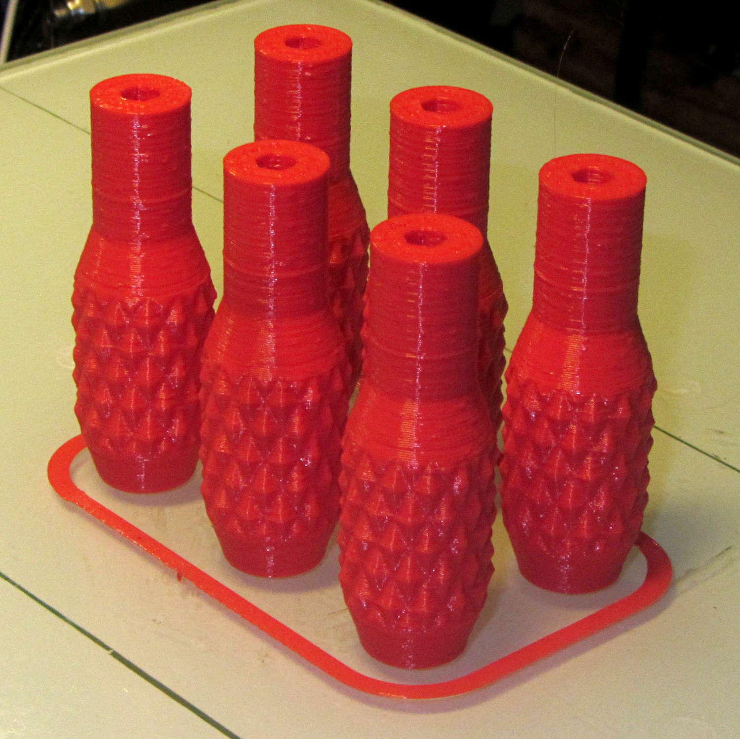
Doing half a dozen doesn’t take much longer than doing a few, because there’s a 20 second minimum layer time in effect and those things don’t have much plastic, so now I have one for the hold-down clamps and another for Show-n-Tell sessions:
Sherline Knobs – M2 platform
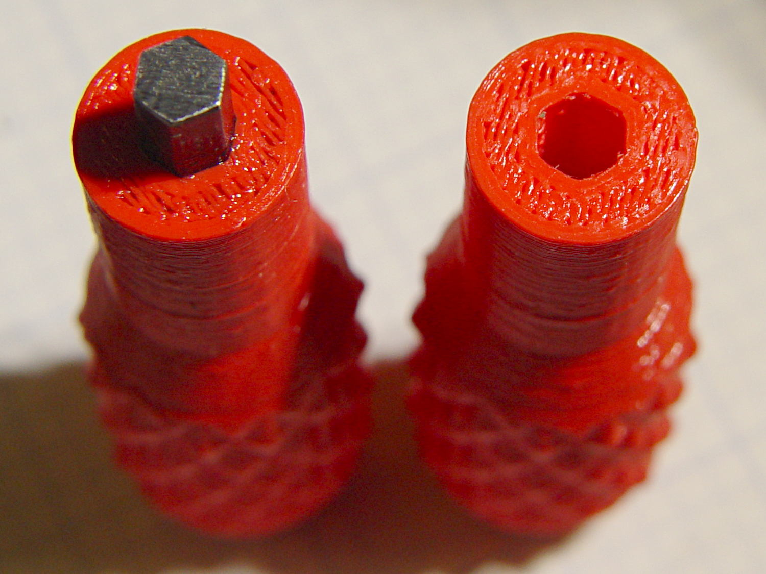
I chopped a 5/32 inch hex key into five 15 mm lengths with a Dremel cutoff wheel, then filed both ends flat and broke the edges. The hex stubs were a press fit in the hex holes, so I finger-started them, grabbed the hex in the drill press, aligned the handle below, and rammed the stub about 5 mm deep. The final depth comes from jamming the wrench into the chuck and pressing firmly, so the stubs project exactly as far as possible:
Sherline Knobs – hex key inserted
One might quibble about the infill on the end; one may go adjust one’s own printer as one prefers.
There’s 0.1 mm more HoleWindage than usual, because these holes must fix a hex shaft, not a circular pin, and the corners need some clearance. They came out a firm press fit: exactly what’s needed.
They’re no good for final tightening of those chuck jaws, but that’s not their purpose…
According to Wikipedia, Polylactic acid, a.k.a. PLA “is soluble in chlorinated solvents, hot benzene, tetrahydrofuran, and dioxane” and is not soluble in acetone, alcohol, or water.
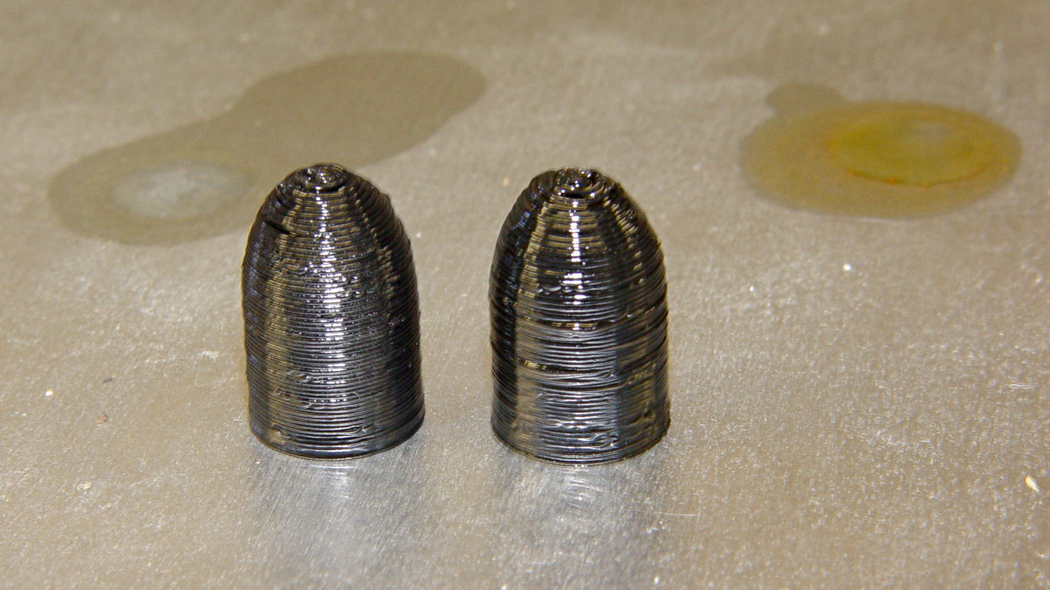
Just to see what happens, I dunked a pair of those 3D printed dummy bullets in Shooter’s Choice Gun Solvent (which has since gone obsolete) and Hoppe’s No. 9 Gun Bore Cleaner (which seems to have been reformulated several times), then let them air-dry in those background puddles:
PLA dummy bullets after solvent bath
Nothing much happened: they’re not soft or gummy, haven’t slumped, and seem undaunted.
That’s in contrast to ABS plastic, which isreadily soluble in acetone and the aromatic hydrocarbons commonly found in solvents used around firearms. Apart from that, ABS would be a slightly better choice on mechanical grounds. I’m not sure the difference really matters for most purposes, given the very wide tolerances on 3D printed objects.