A brace of “Fashion” USB video cameras arrived from halfway around the planet. According to the eBay description and the legend around the lens, they’re “5.0 Megapixel”:
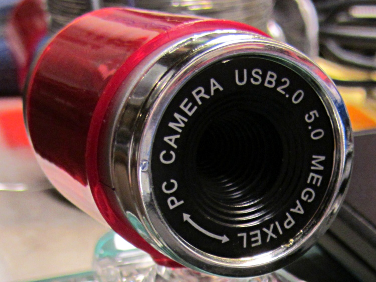
The reality, of course, is that for five bucks delivered you get 640×480 VGA resolution at the hardware level and their Windows driver interpolates the other 4.7 megapixels. VGA resolution will be good enough for my simple needs, particularly because the lens has a mechanical focus adjustment; the double-headed arrow symbolizes the focus action.
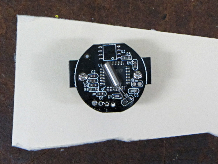
But the case seemed entirely too bulky and awkward. A few minutes with a #0 Philips screwdriver extracted the actual camera hardware, which turns out to be a double-sided PCB with a lens assembly on the front:

The PCB has asymmetric tabs that ensure correct orientation in the case:

In order to build an OpenSCAD model for a more compact case, we need the dimensions of that PCB and those tabs…
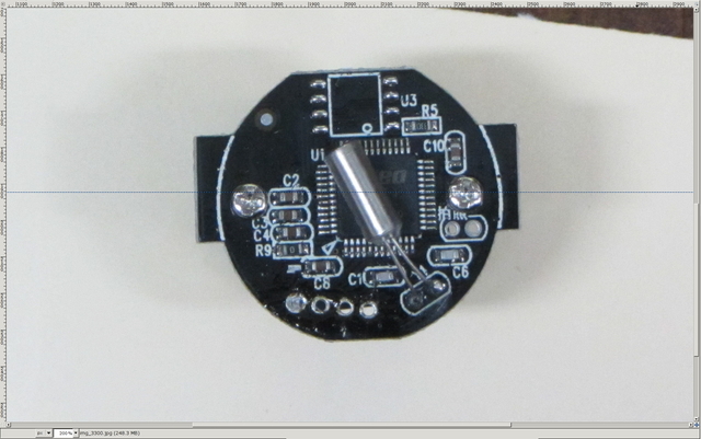
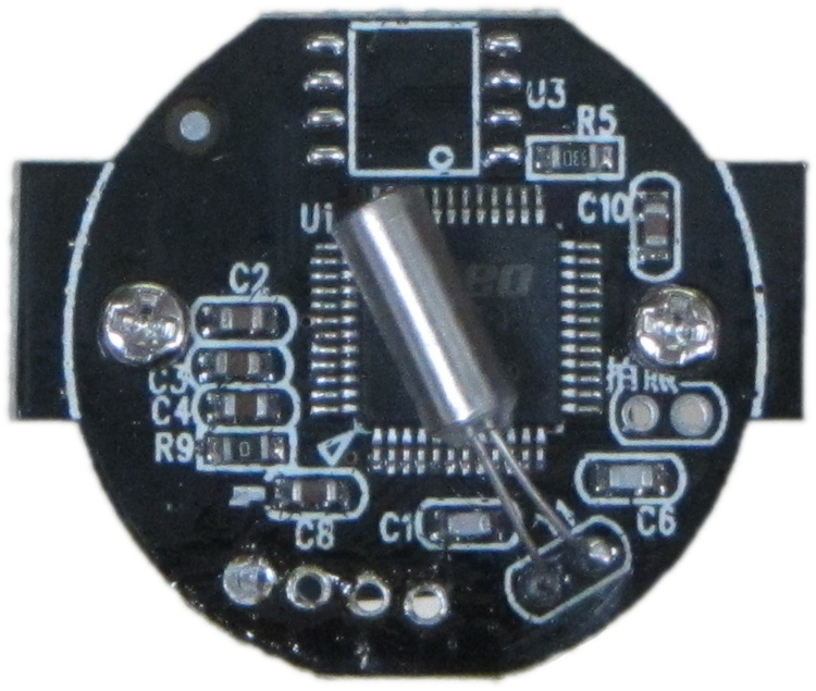
Start with a picture of the back of the PCB against white paper, taken from a few feet to flatten the perspective:
Load it into The GIMP, zoom in, and pull a horizontal guide line down to about the middle of the image:
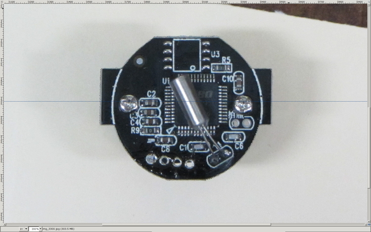
Rotate to align the two screws horizontally (they need not be centered on the guide, just lined up horizontally):

Use the Magic Scissors to select the PCB border (it’s the nearly invisible ragged dotted outline):
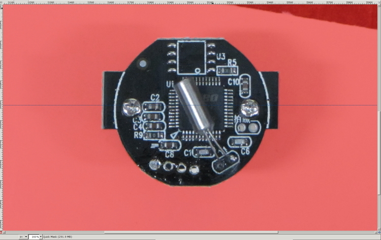
Flip to Quick Mask mode and clean up the selection as needed:
Flip back to normal view, invert the selection (to select the background, not the PCB), and delete the background to isolate the PCB:
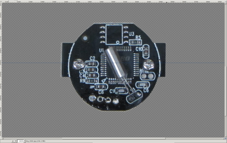
Tight-crop the PCB and flatten the image to get a white background:
Fetch some digital graph paper from your favorite online source. The Multi-color (Light Blue / Light Blue / Light Grey) Multi-weight (1.0×0.6×0.3 pt) grid (1 / 2 / 10) works best for me, but do what you like. Get a full Letter / A4 size sheet, because it’ll come in handy for other projects.
Open it up (converting at 300 dpi), turn it into a layer atop the PCB image, use the color-select tool to select the white background between the grid lines, then delete the selection to leave just the grid with transparency:
We want one minor grid square to be 1×1 mm on the PCB image, sooo…
- Accurately measure a large feature on the real physical object: 27.2 mm across the tabs
- Drag the grid to align a major line with one edge of the PCB
- Count the number of minor square across to the other side of the image: 29.5
- Scale the grid overlay layer by image/physical size: 1.085 = 29.5/27.2
- Drag the grid so it’s neatly centered on the object (or has a major grid intersection somewhere useful)
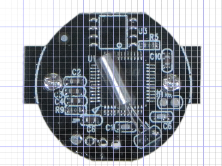
That produces a calibrated overlay:
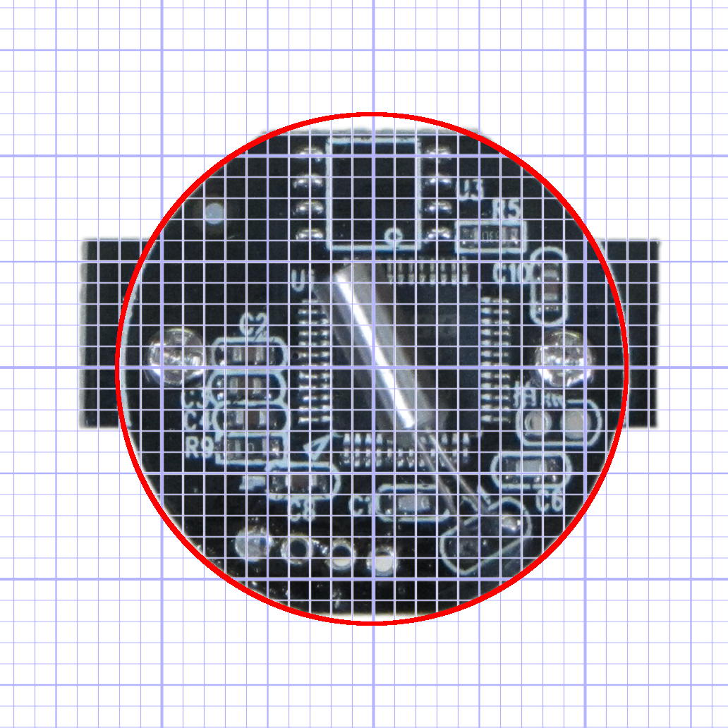
Then it’s just a matter of reading off the coordinates, with each minor grid square representing 1.0 mm in the real world, and writing some OpenSCAD code…

Comments
19 responses to “Measuring Objects for 3D Modeling: USB Video Camera”
Good ideas that help fill the middle between similar start and end points.
I’m thinking bed scanner for model and grid > Autodesk Inventor > 3D print on MG M2.
I’ve had mixed success with scanners; they don’t work well with points on objects more than a few millimeters off the glass. For flat things like PCBs (minus projecting parts!) they work fine.
I need to mill some intake/exhaust headers. Current thinking: put exhaust gasket on scanner, use ubuntu’s simplescan to produce a pdf, run that through pstoedit to get a dxf, and move that into a 3d modeling program or even inkscape, which can directly produce gcode for milling.
It seems like an unsteady ziggurat of software, but it ought to work.
Inkscape has a trace-the-outline function that might produce better vectors directly from a high-contrast scan. Then you hand it directly to the Gcode Tools extension and away you go.
I used an earlier version of the Gcode Tools to do some engraving; it works really well. Engraving text required a precise sequence of gymnastic steps that I got right almost all the time…
I used inkscape with hersheytext and gcode to engrave all our wedding invitations, and it did a great job. Skipping the pdf-dxf steps would be awfully nice. I’ll give this a try.
Thanks for nudging me; I need a stick font for an engraving project and Hershey should work fine…
So the reason I was thinking about going through ps2edit was to get a dxf that I could pull into qcad and dimension, to make sure the distances between two measured points reflected actual dimensions, and that no sneaky scaling had crept in. I don’t know inkscape well enough to know if it can show point-to-point dimensions, although I trust its ability to scale.
Me, either. I suppose you could go both routes, with one for dimension checking and the other for cleanliness of tracing, then compare the answers. Use all the software!
I like to put a ruler into the photograph so I can scale before cropping. Somehow it feels like less work than having to leave the world of the computer and reenter the physical world to caliper the object. :-)
I trust my digital caliper much more than my eyeballometric ruler-fu… [grin]
I trust my ruler-fu about as much as I trust my 3D printer. :-)
I did this the old way with a cam for the door latch in my Triumph Spitfire last month: put item on graph paper, trace with a mechanical pencil, read off the numbers, print. I’d really like to do this automatically, though. I’ve built a touch sensor for the cnc mill but have yet to spend the time/energy to get it working, although there’s a lot of interesting stuff being done right now by people who are touch-sensing pcb height for cnc pcb milling and their code would be a good starting point for a 3d touch-scan. (I believe linuxcnc has a touch-scan routine on one of their pages, too, don’t they?)
How quaint! [grin]
Probably worked better than the storm door latch cam I made on the Sherline CNC mill, though. [Censored] thing had a square hole down the middle that I gnawed out with a square file and swore never again… except that I’ve replaced three identical latches on the three outside doors so far. I’ll definitely use 3D printing next time, even though plastic doesn’t have The Right Stuff.
Both for mapping an object and, more important for me, compensating for platform inclination / non-flatness through the
probekinskinematics module. Most of that stuff gets buried in the LinuxCNC Wiki and requires considerable persistence to unearth… but the truth is out there!I think the gotcha with general 3D probing on an XYZ machine is having the point cloud describe only the top surface; I vaguely recall nested XY loops that cover the anticipated range at some reasonable resolution. Given that the top is the only surface you can mill, it might not be such a Bad Thing, but I don’t know how / if you could combine that cloud with a similar touch scan of the bottom surface (and sides?) to get a good solid model.
In my case the graph paper approach made sense as I did the whole process on a car ride with no access to a computer. However, today I was poking around looking at dry sump systems design discussions and found some people who had scanned an oil pan, and then used SolidWorks to just eyeball-outline the dimensions to get a cnc drill file, which is another reasonably nice approach.
I’ve a friend who designs 3d scanning hardware. I’ll run the solid model question past him.
btw I’ve had some luck with 3d-printing shapes, then cutting brass or bronze bushings on the lathe, heating them up in boiling water, and pressing them into bores in the 3d print and chucking the works in ice-cold water.
I like it!
Something like that might work for the cam: the square hole has plenty of meat around the edges for a plastic shape and maybe I could embed rods in the sliding surfaces to take the friction. It’s a pretty simple design, with a stamped-and-bent steel bar (which I’ve also replaced) sliding against the brass cam. Guess what wears away after half a century?
Thanks for the hint…
Yet another thought on the storm door cam/bar combination. Is it practical to make a bar with a sacrificial wear pad out of Delrin or such? Sounds like the cam is a PITA to reproduce, and if some easier-to-fix element can be designed to go first, it would help. (I can tell I’m getting
wiserolder–I’m paying more attention to how to fix what I’ve already fixed before.)OK, I’ll write up what I’ve done and you folks can poke holes in it… [grin]
[…] The discussion following that post on getting feature coordinates from an existing part reminded me of an old project that I’d written up for Digital Machinist: making repair parts for the half-century old storm doors on our house. Here’s the whole latch, with a replacement drawbar and cam: […]
since we’re too deeply nested to reply in the right place: http://wiki.inkscape.org/wiki/index.php/Frequently_asked_questions#How_do_I_measure_distances_and_angles.3F
so it looks like I’m set. I’ll give it a run tonight if I have time.