Ed Nisley's Blog: Shop notes, electronics, firmware, machinery, 3D printing, laser cuttery, and curiosities. Contents: 100% human thinking, 0% AI slop.
This is a classic case of investing more time and effort creating the fixture than machining the parts.
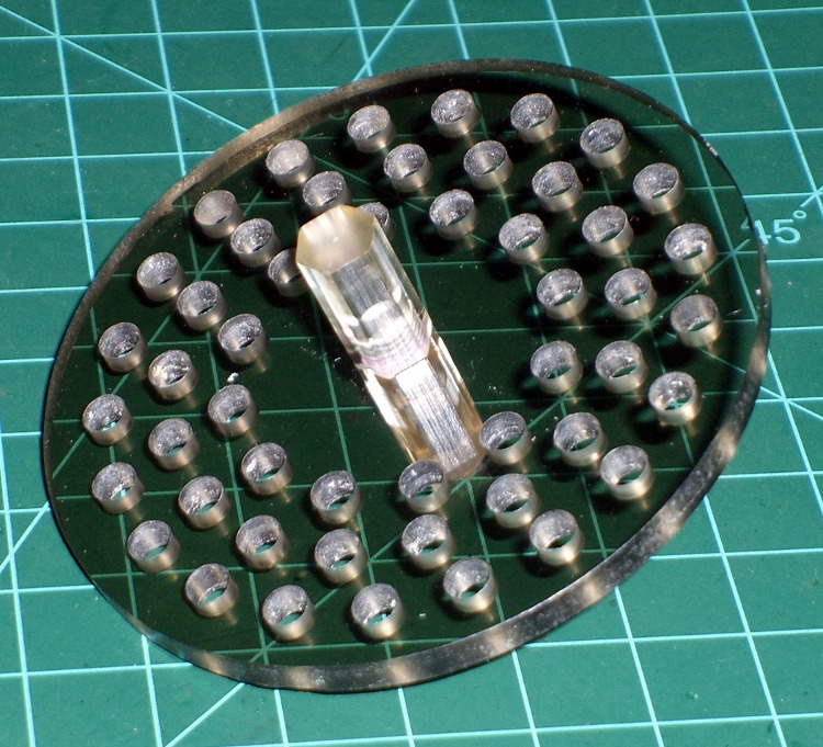
Start by squaring up the block, which came from the end of a random chunk of smoke gray polycarbonate, with two 10-32 holes matching the tooling plate hole spacing:
Corner Clip Fixture – squaring
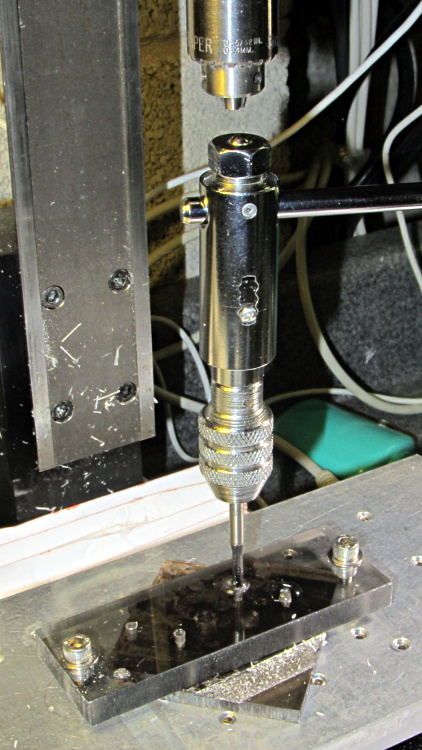
Then drill-and-tap four holes:
Corner Clip Fixture – tapping
The left station will be for drilling the blanks clamped under a sacrificial sheet, so those screw holes aren’t used for anything other than clearance; the top millimeter will get chewed up pretty quickly. The screws in the right station will clamp a stack of drilled blanks under a cover plate. If I went into production, I could see using both stations for both functions, but …
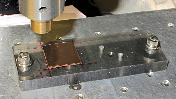
There’s a locating pip in the front left corner that works perfectly with laser alignment:
Corner Clip Fixture – aligning
The blank sheets show where they’d be located for drilling, minus the sacrificial sheet and its clamps that you’ll see below.
The G54 coordinate system origin sits at the locating pip. The G-Code then slaps a G55 origin at each of the two stations in turn to simplify their coordinates, with offsets from M54:
Drilling = (+5,+5)
Milling = (+40,+5)
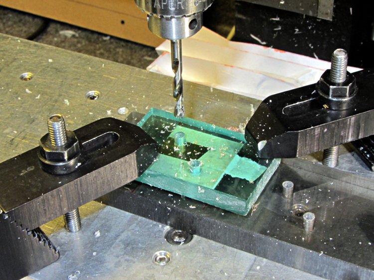
With all that in hand: stack, clamp, and drill some blanks:
Corner Clip Fixture – drilling
I tried milling a single drilled blank with a sacrificial plastic top plate:
Corner Clip Fixture – first milling setup
But that didn’t work well. I don’t know if this was due to an inept combination of climb milling, using the wrong speed / feed / material / cutter, and just poor style, but the edges of the blank mashed against the clamp plate and curled, instead of cutting cleanly:
Corner Clip Fixture – rounded-over milled edges
So I made a pair of aluminum plates to clamp both sides of the blanks, then milled another stack:
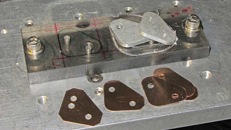
That worked quite well, although the top and bottom clips needed some slight attention from a riffler file and I did break the edges on all the clips. This shows four new clips along with a hand-cut prototype:
Corner Clip Fixture – end result
So I made a dozen more clips, picked the best eight for two sets, sent one set to Dan, installed the other, and … now I have a bunch of spares.
I suppose I should sell clip sets on Etsy / eBay to all the other M2 owners, but I have no idea how to price ’em. If you want some fancy corner clips, send whatever you think they’re worth … [grin]
The CNC version of the corner clips looks much better than the prototypes:
M2 glass retaining clip
Tightening the screws until the clip just flattens puts enough force on the glass + heat spreader stack to hold it firmly against the balls in the bottom pad. The solid rubber L-shaped bumpers and screws hold the glass in position against XY forces… and the whole affair looks much better than the original (and perfectly serviceable) bulldog clips. These clips free up the entire surface of the glass plate, minus four 12 mm triangles that you could, if you were desperate, print right over.
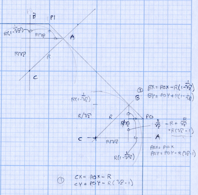
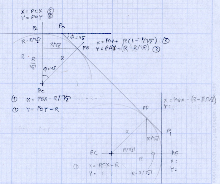
Although it’d be easier to just hack out an angular clip, I wrote a bit of G-Code to put a nice radius on each corner. The clip sits atop the rubber bumper with a 0.5 mm margin to keep the metal edges away from fingers; they’re smooth, but it’s still a strip of 6 mil (= 0.15 mm) phosphor bronze and feels a lot like a knife edge if you press hard enough.
The radius on the three outside corners is a special-case solution of the general circle-through-three-points problem, taking advantage of the symmetry and right-triangle-ness of the corners. This sketch shows the details:
M2 Platform Clip Doodles 4 – corner fairing with margin
The two corners on the bevel over the glass plate have a fixed radius. I reworked my original fairing arc solution for outside cutting and doodled it up for this situation:
M2 Platform Clip Doodles 5 – bevel full solution
The outside corner radius worked out to 5 mm and I set the bevel radius at 3 mm. I think the latter made those corners a bit too sharp, but it’s Good Enough for my simple needs.
Drilling and machining the clips required a fixture:
I used cutter diameter compensation to mill the edges, starting oversize by 1.5 mm and working downward by 0.5 mm on each pass to the actual diameter. That gradually trimmed off the edges without any excitement, so I could start with rough-trimmed stock and not worry about precision hand trimming.
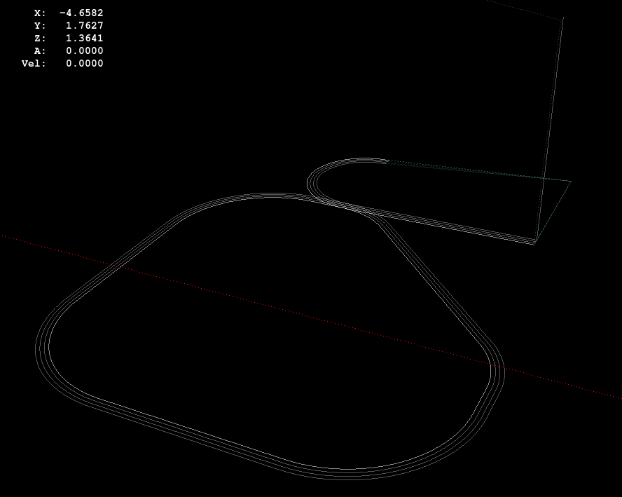
I thought climb milling (CW around the part) would produce better results, but it tended to smear the phosphor bronze against the fixture:
M2 Corner Clips – Climb milling tool paths
Conventional milling (CCW around the part) actually worked, but it required fancier entry and exit moves:
M2 Corner Clips – Conventional milling tool paths
This part is the kind and size of machining perfectly suited to a Sherline CNC mill…
The LinuxCNC G-Code source:
( M2 Build Platform Corner Clips )
( Ed Nisley - KE4ZNU - July 2013 )
( Fixture origin at right-front corner pip )

( Flow Control )
#<_Do_Drill> = 0		( Drill two holes in clip )
#<_Do_Mill> = 1			( Mill clip outline )
#<_Climb_Mill> = 0		( 0 = conventional 1 = climb)

( Fixture info )
#<_Drill_X_Fixture> = 5.0	( Drill station origin )
#<_Drill_Y_Fixture> = 5.0

#<_Drill_Num> = 30			( Drill number in tool table)
#<_Drill_Retract> = 15
#<_Drill_Depth> = -1.0
#<_Drill_Feed> = 300
#<_Drill_Speed> = 3000

#<_Mill_X_Fixture> = 40.0	( Mill station origin )
#<_Mill_Y_Fixture> = 5.0

#<_Mill_Num> = 3			( Mill number in tool table)
#<_Mill_Dia> = 4.60			( actual tool diameter)
#<_Mill_Dia_Incr> = 0.50
#<_Mill_Dia_Steps> = 3
#<_Mill_Retract> = 15
#<_Mill_Depth> = -0.5
#<_Mill_Feed> = 300
#<_Mill_Speed> = 8000

(----------------)

(  Initialize first tool length at probe switch )
(     Assumes G59.3 is still in machine units, returns in G54 )
(  ** Must set these constants to match G20 / G21 condition! )

#<_Probe_Speed>     = 400            ( set for something sensible in mm or inch )
#<_Probe_Retract>   =   1            ( ditto )

O<Probe_Tool> SUB

G49                     ( clear tool length compensation )
G30                     ( move above probe switch )
G59.3                   ( coord system 9 )

G38.2 Z0 F#<_Probe_Speed>           ( trip switch on the way down )
G0 Z[#5063 + #<_Probe_Retract>]     ( back off the switch )
G38.2 Z0 F[#<_Probe_Speed> / 10]    ( trip switch slowly )

#<_ToolZ> = #5063                    ( save new tool length )

G43.1 Z[#<_ToolZ> - #<_ToolRefZ>]    ( set new length )

G54                     ( coord system 0 )
G30                     ( return to safe level )

O<Probe_Tool> ENDSUB

(-------------------)
(-- Initialize first tool length at probe switch )

O<Probe_Init> SUB

#<_ToolRefZ> = 0.0      ( set up for first call )

O<Probe_Tool> CALL

#<_ToolRefZ> = #5063    ( save trip point )

G43.1 Z0                ( tool entered at Z=0, so set it there )

O<Probe_Init> ENDSUB

(-------------------)
(-- Mill one pass around outline with tool diameter passed in #1 )

O<MillOutline> SUB

#<X_Size> = 22.0		( size of support spider pad = nominal clip size )
#<Y_Size> = 22.0
#<Base_Bevel> = 3.2		( X or Y length of corners clipped from spider pad )

#<Bevel_Size> = 9.0		( remaining part of trimmed edges on clip )
#<Bevel_Radius> = 3.0	( fairing radius at bevel corners on clip)

#<R_Div_Root2> = [#<Bevel_Radius> / SQRT[2]]
#<R_1M_Recip_R2> = [#<Bevel_Radius> * [1 - 1/SQRT[2]]]
#<R_Root2_M1> = [#<Bevel_Radius> * [SQRT[2] - 1]]

#<Margin> = 0.5			( recess inside of nominal )

#<X_Min> = [#<Margin>]
#<X_Max> = [#<X_Size> - #<Margin>]

#<Y_Min> = [#<Margin>]
#<Y_Max> = [#<Y_Size> - #<Margin>]

#<Corner_Rad> = [[#<Margin> * [1 - SQRT[2]] + [#<Base_Bevel> / SQRT[2]]] / [SQRT[2] - 1]]

O<Climb> IF [#<_Climb_Mill>]

G0 X#<X_Min> Y[#<Y_Max> + 3*#<_Mill_Dia>]
G1 Z#<_Mill_Depth> F#<_Mill_Feed>

G41.1 D#1

G3 X[#<X_Min>] Y#<Y_Max> I0 J[0-1.5*#<_Mill_Dia>]	( cutter comp on: entry move)

G1 X[#<Bevel_Size> - #<R_Root2_M1>]
G2 X[#<Bevel_Size> + #<R_1M_Recip_R2>] Y[#<Y_Max> - #<R_1M_Recip_R2>] J[0-#<Bevel_Radius>]

G1 X[#<X_Max> - #<R_1M_Recip_R2>] Y[#<Bevel_Size> + #<R_1M_Recip_R2>]
G2 X#<X_Max> Y[#<Bevel_Size> - #<R_Root2_M1>] I[0-#<R_Div_Root2>] J[0-#<R_Div_Root2>]

G1 Y[#<Y_Min> + #<Corner_Rad>]
G2 X[#<X_Max> - #<Corner_Rad>] Y#<Y_Min> I[0-#<Corner_Rad>] J0

G1 X[#<X_Min> + #<Corner_Rad>]
G2 X#<X_Min> Y[#<Y_Min> + #<Corner_Rad>] I0 J#<Corner_Rad>

G1 Y[#<Y_Max> - #<Corner_Rad>]
G2 X[#<X_Min> + #<Corner_Rad>] Y#<Y_Max> I#<Corner_Rad> J0

G40

G0 X#<X_Min> Y[#<Y_Max> + 3*#<_Mill_Dia>]
(G3 X#<Bevel_Size> Y[#<Y_Max> + 3*#<_Mill_Dia>] I0 J[1.5*#<_Mill_Dia>])	( cutter comp off: safe exit)

G0 X#<X_Min>			( return to start)

O<Climb> ELSE

G0 X#<X_Size> Y[#<Y_Size> + #1/2]

G1 Z#<_Mill_Depth> F#<_Mill_Feed>

G42.1 D#1

G1 X#<Bevel_Size> Y[#<Y_Max>]	( cutter comp on: entry move)

G1 X[#<X_Min> + #<Corner_Rad>]
G3 X#<X_Min> Y[#<Y_Max> - #<Corner_Rad>] I0 J[0-#<Corner_Rad>]

G1 Y[#<Y_Min> + #<Corner_Rad>]
G3 X[#<X_Min> + #<Corner_Rad>] Y[#<Y_Min>] I#<Corner_Rad> J0

G1 X[#<X_Max> - #<Corner_Rad>]
G3 X[#<X_Max>] Y[#<Y_Min> + #<Corner_Rad>] I0 J#<Corner_Rad>

G1 Y[#<Bevel_Size> - #<R_Root2_M1>]
G3 X[#<X_Max> - #<R_1M_Recip_R2>] Y[#<Bevel_Size> + #<R_1M_Recip_R2>] I[-#<Bevel_Radius>]

G1 X[#<Bevel_Size> + #<R_1M_Recip_R2>] Y[#<Y_Max> - #<R_1M_Recip_R2>]
G3 X[#<Bevel_Size> - #<R_Root2_M1>] Y#<Y_Max> I[-#<R_Div_Root2>] J[-#<R_Div_Root2>]

G2 Y[#<Y_Max> + 3*#<_Mill_Dia>] J[#<_Mill_Dia>*1.5]		( get away from corner)
G40

G0 X#<X_Size>					( cutter comp off: safe exit)
G0 Y[#<Y_Size> + #1/2]			( return to start)

O<Climb> ENDIF

O<MillOutline> ENDSUB

(----------------)
( Start machining... )

G17 G40 G49 G54 G80 G90 G94 G99	( reset many things )

G21								( metric! )
G91.1 							( incremental arc centers)

(msg,Verify: G30.1 position in G54 above tool change switch? )
M0
(msg,Verify: fixture origin XY touched off? )
M0
(msg,Verify: Current tool Z=0 touched off? )
M0

( Set up probing)
O<Probe_Init> CALL
T0 M6

(---- Drill holes)

O<DoDrill> IF [#<_Do_Drill>]

(debug,Insert drill tool = #<_Drill_Num>)
T#<_Drill_Num> M6
O<Probe_Tool> CALL
(debug,Set spindle to #<_Drill_Speed> rpm )
M0

G0 X#<_Drill_X_Fixture> Y#<_Drill_Y_Fixture>
G0 Z#<_Drill_Retract>

G10 L20 P2 X0 Y0 Z#<_Drill_Retract>	( P2 = G55)
G55					( drill station coordinates )

G81 X5.0 Y15.0 Z#<_Drill_Depth> R#<_Drill_Retract> F#<_Drill_Feed>

G81 X15.0 Y5.0

G54

O<DoDrill> ENDIF

(---- Mill outline )
( Start with large diameter and end with actual diameter to trim in stages)

O<DoMill> IF [#<_Do_Mill>]

(debug,Insert mill tool = #<_Mill_Num>)
T#<_Mill_Num> M6
O<Probe_Tool> CALL
(debug,Set spindle to #<_Mill_Speed> rpm )
M0

G0 X#<_Mill_X_Fixture> Y#<_Mill_Y_Fixture>
G0 Z#<_Mill_Retract>

G10 L20 P2 X0 Y0 Z#<_Mill_Retract>	( P2 = G55)
G55					( mill station coordinates )

#<PassCount> = 0

O<MillLoop> DO
#<Diameter> = [#<_Mill_Dia> + [#<_Mill_Dia_Steps> - #<PassCount>]*#<_Mill_Dia_Incr>]

O<MillOutline> CALL [#<Diameter>]

#<PassCount> = [#<PassCount> + 1]
O<MillLoop> WHILE [#<PassCount> LE #<_Mill_Dia_Steps>]

( Finishing pass with zero cut )
O<MillOutline> CALL [#<Diameter>]

G0 Z#<_Mill_Retract>
G54

O<DoMill> ENDIF

G30

(msg,Done!)
M2
The rest of the doodles, which don’t match up with the final G-Code because they represent the earliest versions of the layout:
I planned to use an old Dell Inspiron 531S AMD desktop for the LinuxCNC installation, but it turned out to have terrible interrupt latency, despite fiddling with all the available BIOS settings and video drivers. Mostly, it ran fine, but would occasionally burp up a millisecond-long latency spike for no apparent reason. So it’s now on the harvest / recycle heap.
A new-to-me off-lease Dell Optiplex 760 Core 2 Duo in the SDT (Small Desktop Tower) configuration has similar latency numbers:
Optiplex 760 latency – isolcpu 1
What’s important here is that the latency remains rock-solid stable at those numbers. Contrary to my experience with the D520 and D525 Atoms, isolating one CPU for the real-time tasks didn’t make any noticeable difference, but it’s running that way because the overall performance isn’t a problem.
Latency around 20 μs is near the upper limit for successful software step generation at any reasonable pace; the LinuxCNC description has more details. In round numbers, running the M2 at 500 mm/s needs a 40 kHz step rate in 1/16 microstep mode = a 25 μs period, which means 20 μs of jitter wouldn’t work well at all. Which is why I’m using Mesa FPGA card to get hardware step generation: it makes such problems Go Away.
The Optiplex arrived with Windows Vista Business preinstalled; it dates back to mid-2009. I used System Rescue CD to shrink the Windows partition, added a few more, then installed LinuxCNC direct from the CD image (based on Ubuntu 10.04 LTS) and Xubuntu 13.04. The latter serves as a general-purpose installation for times when I don’t need LinuxCNC, because 10.04 is pretty much obsolete for anything other than real-time control.
Digression 1: Yes, 10.04 LTS. TheRTAI project hasn’t released the patches that will slip the real-time kernel under the stock 3.x Linux kernel: LinuxCNC remains stuck at 10.04 LTS. Those changes have been coming Real Soon Now for quite a while; as with most Open Source projects, they could use more manpower and money. This isn’t a problem, as LinuxCNC is used for motion control, not a general-purpose operating system.
The SDT case has room for two PCI cards and one PCI-E video card, so I installed the dual-head video card that couldn’t handle the U2711 monitor’s dual-DVI connection (although I’m using only DVI Output 1) and a Mesa 5i25. The middle “card” is actually a tiny PCB connected to a ribbon cable that brings out a second serial port (remember serial ports?) and what could be either or both of a PS2 keyboard or mouse connection (remember PS/2?).
Optiplex 760 SDT – dual DVI – serial – 5i25
The back panel has a parallel printer port (which may come in handy for something) and a serial port, although you’re expected to have USB mice and keyboards these days. The front panel even has a floppy drive…
Digression 2: LinuxCNC does not require a parallel printer port; this seems to be a common misconception among folks who don’t actually know how it works. The Mesa 5i25 FPGA card with a 7i76 step-direction daughter board provides high-resolution timing for five axes, rotary encoder inputs, a bunch of buffered digital I/O bits, a watchdog timer, plus various other useful odds and ends, all behind handy screw terminals.
The Optiplex 760 has on-board VGA-class video that would also work fine, but the monitor I’m using has its VGA input connected to the box driving the Sherline mill and an unused DVI input. Having that dual-DVI monitor card lying around, I figured I could attach the same monitor to both systems and just poke the monitor’s input section button; I’ve found KVM switches unreliable in this application.
The usual setup preps the system for public-key SSH on a nonstandard port, sets up the NFS mounts, and tweaks this-and-that: it’s running just fine.
Digression 3: SSH kvetches when you swap server boxes at the same IP address, as well it should. If you’re foolish enough to have two separate Linux installs on the same box with the same IP, SSH reminds you every time you boot the other distro…
Now that Google encrypts your search terms (so they can sell the results to their customers), it’s harder to determine where folks come from. WordPress does report whatever search terms it can, though, and a recent search for plastic kitchen sink strainer caught my eye.
Here’s what you get (or, at least, what I got on that day) by feeding those words into Google Image Search:
Search engine optimization like that is to die for, eh?
The related post described a cleanup operation that didn’t really achieve very much in the long run:
Skimming the strainer
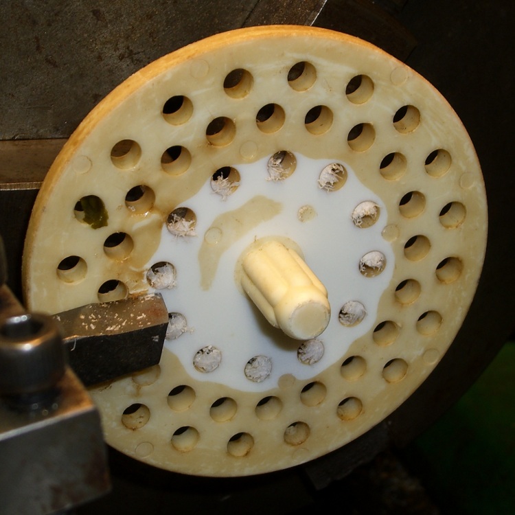
Some years ago I machined a pair of smoke gray acrylic sink strainers (using LinuxCNC / EMC2 loops and trig functions) on the Sherline and wrote it up for my Digital Machinist column. They came out quite nicely:
CNC Sink Strainer
Then I did a 3D printed version on the Thing-O-Matic:
Turns out that there’s no difference between the Mac and PC versions of the Logitech Dual Action Gamepad:
Logitech Dual Action Gamepads – Mac vs PC
I picked up a Mac version cheap from the usual eBay seller and discovered that LinuxCNC / HAL was perfectly happy. That wasn’t too surprising; they have the same model and part numbers. Most likely, the only difference was the CD and maybe the Quick Start Guide that I didn’t get in the opened retail box…
So now I have either a hot backup for the Joggy Thing or one for a different box.
Most likely, it was cheap because nobody wants a blue-and-black peripheral next to their shiny white Mac…
Here’s a combined and sorted list of all the G-Code and M-Code commands for (as many of) the Free Software G-Code interpreters (that I could find) relevant to DIY 3D printing. With any luck, I now know:
What a given command does
What other interpreters do with that command
The short descriptions come from tables on the original source pages, perhaps with a bit of massaging to make things more uniform; I did as little rearranging and editing as possible.
If you see anything wrong or have another G-Code interpreter I should include, let me know…
3D Printer G-Code and M-Code Commands

27 Feb 2013
Ed Nisley - KE4ZNU

V3 - NIST RS274NGC V3- http://www.nist.gov/manuscript-publication-search.cfm?pub_id=823374
LC - LinuxCNC - http://www.linuxcnc.org/docs/
RG - ReplicatorG - http://replicat.org/gcodes and /mcodes
JF - Jetty Firmware - http://replicat.org/mcodes at bottom
RR - RepRap - http://reprap.org/wiki/G_codes (cross-linked from many G-Code pages)
MF - Marlin Firmware dialect of RR (via Dan Newman)

G0  LC  Coordinated Straight Motion Rapid
G0  MF  same as G1
G0  RG  Rapid Motion
G0  RR  Rapid move
G0  V3  rapid positioning
G1  LC  Coordinated Straight Motion Feed Rate
G1  MF  Coordinated Movement X Y Z E
G1  RG  Coordinated Motion
G1  RR  Controlled move
G1  V3  linear interpolation
G2  LC  Coordinated Helical Motion Feed Rate
G2  MF  CW ARC
G2  RG  Arc - Clockwise
G2  V3  circular/helical interpolation (clockwise)
G3  LC  Coordinated Helical Motion Feed Rate
G3  MF  CCW ARC
G3  RG  Arc - Counter Clockwise
G3  V3  circular/helical interpolation (counterclockwise)
G4  LC  Dwell
G4  MF  Dwell S<seconds> or P<milliseconds>
G4  RG  Dwell
G4  RR  Dwell
G4  V3  dwell
G5.1    LC  Quadratic B-Spline
G5.2    LC  NURBs Block Open
G5.3    LC  NURBs Block Close
G7  LC  Diameter Mode (lathe)
G8  LC  Radius Mode (lathe)
G10 LC  L10 Set Tool Table, Calculated, Workpiece
G10 LC  L11 Set Tool Table, Calculated, Fixture
G10 LC  L1  Set Tool Table Entry
G10 LC  L20 Coordinate System Origin Setting Calculated
G10 LC  L2  Coordinate System Origin Setting
G10 RG  Create Coordinate System Offset from the Absolute one
G10 RR  Head Offset
G10 V3  coordinate system origin setting
G17 LC  Arc plane XY
G17 RG  Select XY plane (default)
G17 V3  XY-plane selection
G17.1   LC  Arc plane UV
G18 LC  Arc plane ZX
G18 RG  Select XZ plane (not implemented)
G18 V3  XZ-plane selection
G18.1   LC  Arc plane WU
G19 LC  Arc plane YZ
G19 RG  Select YX plane (not implemented)
G19 V3  YZ-plane selection
G19.1   LC  Arc plane VW
G20 LC  Unit of Measure - inch
G20 RG  Inches as units
G20 RR  Set Units to Inches
G20 V3  inch system selection
G21 LC  Unit of Measure - millimeter
G21 RG  Millimeters as units
G21 RR  Set Units to Millimeters
G21 V3  millimeter system selection
G28 LC  Go to Predefined Position
G28 MF  Home all Axis
G28 RG  Home given Axes to maximum
G28 RR  Move to Origin
G28 V3  return to home
G28.1   LC  Store Predefined Position
G29-G32 RR  Bed probing
G30 LC  Go to Predefined Position
G30 RG  Go Home via Intermediate Point (not implemented)
G30 V3  return to secondary home
G30.1   LC  Store Predefined Position
G31 RG  Single probe (not implemented)
G32 RG  Probe area (not implemented)
G33 LC  Spindle Synchronized Motion
G33.1   LC  Rigid Tapping
G38.2   LC  Probe toward, stop on contact, error
G38.2   V3  straight probe
G38.3   LC  Probe toward, stop on contact
G38.4   LC  Probe away, stop on release, error
G38.5   LC  Probe away, stop on release
G40 LC  Cancel Cutter Compensation
G40 V3  cancel cutter radius compensation
G41 LC  Cutter Compensation - left
G41 V3  start cutter radius compensation left
G41.1   LC  Dynamic Cutter Compensation - left
G42 LC  Cutter Compensation - right
G42 V3  start cutter radius compensation right
G42.1   LC  Dynamic Cutter Compensation - right
G43 LC  Use Tool Length Offset from Tool Table
G43 V3  tool length offset (plus)
G43.1   LC  Dynamic Tool Length Offset
G49 LC  Cancel Tool Length Offset
G49 V3  cancel tool length offset
G53 LC  Motion in Machine Coordinate System
G53 RG  Set absolute coordinate system
G53 V3  motion in machine coordinate system
G54-G59 RG  Use coordinate system from G10 P0-5
G54 LC  Select Coordinate System 1
G54 V3  use preset work coordinate system 1
G55 LC  Select Coordinate System 2
G55 V3  use preset work coordinate system 2
G56 LC  Select Coordinate System 3
G56 V3  use preset work coordinate system 3
G57 LC  Select Coordinate System 4
G57 V3  use preset work coordinate system 4
G58 LC  Select Coordinate System 5
G58 V3  use preset work coordinate system 5
G59 LC  Select Coordinate System 6
G59 V3  use preset work coordinate system 6
G59.1   LC  Select Coordinate System 7
G59.1   V3  use preset work coordinate system 7
G59.2   LC  Select Coordinate System 8
G59.2   V3  use preset work coordinate system 8
G59.3   LC  Select Coordinate System 9
G59.3   V3  use preset work coordinate system 9
G61 LC  Path Control Mode - exact path
G61 V3  set path control mode: exact path
G61.1   LC  Path Control Mode - exact stop (same as G61)
G61.1   V3  set path control mode: exact stop
G64 LC  Path Control Mode - Optional Tolerance
G64 V3  set path control mode: continuous
G73 LC  Drilling Cycle with Chip Breaking
G76 LC  Multi-pass Threading Cycle (Lathe)
G80 LC  Cancel Motion Modes
G80 V3  cancel motion mode (including any canned cycle)
G81 LC  Drilling Cycle
G81 V3  canned cycle: drilling
G82 LC  Drilling Cycle with Dwell
G82 V3  canned cycle: drilling with dwell
G83 LC  Drilling Cycle with Peck
G83 V3  canned cycle: peck drilling
G84 V3  canned cycle: right hand tapping
G85 LC  Boring Cycle, No Dwell, Feed Out
G85 V3  canned cycle: boring, no dwell, feed out
G86 LC  Boring Cycle, Stop, Rapid Out
G86 V3  canned cycle: boring, spindle stop, rapid out
G87 V3  canned cycle: back boring
G88 V3  canned cycle: boring, spindle stop, manual out
G89 LC  Boring Cycle, Dwell, Feed Out
G89 V3  canned cycle: boring, dwell, feed out
G90 LC  G91 Distance Mode
G90 MF  Use Absolute Coordinates
G90 RG  Absolute Positioning
G90 RR  Set to Absolute Positioning
G90 V3  absolute distance mode
G90.1   LC  Arc Distance Mode - absolute IJK
G91 MF  Use Relative Coordinates
G91 RG  Relative Positioning
G91 RR  Set to Relative Positioning
G91 V3  incremental distance mode
G91.1   LC  Arc Distance Mode - incremental IJK
G92.1   V3  cancel offset coordinate systems and set parameters to zero
G92 LC  Coordinate System Offset
G92 MF  Set current position to cordinates given
G92 RG  Define current position on axes
G92 RR  Set Position
G92 V3  offset coordinate systems and set parameters
G92.1   LC  Cancel Coordinate System Offsets
G92.2   LC  Cancel Coordinate System Offsets
G92.2   V3  cancel offset coordinate systems but do not reset parameters
G92.3   LC  Restore Axis Offsets
G92.3   V3  apply parameters to offset coordinate systems
G93 LC  Feed Mode - Inverse time
G93 V3  inverse time feed rate mode
G94 LC  Feed Mode - Units per minute
G94 RG  Feed rate mode (not implemented)
G94 V3  units per minute feed rate mode
G95 LC  Feed Mode - Units per revolution
G96 LC  Constant Surface Speed
G97 LC  RPM Mode
G97 RG  Spindle speed rate
G98 LC  Canned Cycle Z Retract Mode
G98 V3  initial level return in canned cycles
G99 LC  Canned Cycle Z Retract Mode
G99 V3  R-point level return in canned cycles
G161    RG  Home negative
G162    RG  Home positive

M0  LC  Program Pause
M0  RG  Unconditional Halt (not supported on SD)
M0  RR  Stop
M0  V3  program stop
M1  LC  Program Pause - optional
M1  RG  Optional Halt (not supported on SD)
M1  RR  Sleep
M1  V3  optional program stop
M2  LC  Program End
M2  RG  End program
M2  V3  program end
M3  LC  Spindle Control - clockwise ON
M3  RG  spindle on, CW
M3  RR  Spindle On, Clockwise (CNC specific)
M3  V3  turn spindle clockwise
M4  LC  Spindle Control - counterclockwise ON
M4  RG  spindle on, CCW
M4  RR  Spindle On, Counter-Clockwise (CNC specific)
M4  V3  turn spindle counterclockwise
M5  LC  Spindle Control - OFF
M5  RG  spindle off
M5  RR  Spindle Off (CNC specific)
M5  V3  stop spindle turning
M6  LC  Tool Change
M6  RG  Tool change. This code waits until the toolhead is ready before proceeding. This is often used to wait for a toolhead to reach the its set temperature before beginning a print. ReplicatorG also supports giving a timeout with M6 P<secs>.
M6  V3  tool change
M7  LC  Coolant Control - mist ON
M7  RG  coolant A on (flood coolant)
M7  RR  Mist Coolant On (CNC specific)
M7  V3  mist coolant on
M8  LC  Coolant Control - flood ON
M8  RG  cooland B on (mist coolant)
M8  RR  Flood Coolant On (CNC specific)
M8  V3  flood coolant on
M9  LC  Coolant Control - OFF
M9  RG  all coolants off
M9  RR  Coolant Off (CNC specific)
M9  V3  mist and flood coolant off
M10 RG  close clamp
M10 RR  Vacuum On (CNC specific)
M11 RG  open clamp
M11 RR  Vacuum Off (CNC specific)
M13 RG  spindle CW and coolant A on
M14 RG  spindle CCW and coolant A on
M17 MF  Enable/Power all stepper motors
M17 RG  enable motor(s)
M17 RR  Enable/Power all stepper motors
M18 MF  Disable all stepper motors; same as M84
M18 RG  disable motor(s)
M18 RR  Disable all stepper motors
M20 MF  List SD card
M20 RR  List SD card
M21 MF  Init SD card
M21 RG  open collet
M21 RR  Initialize SD card
M22 MF  Release SD card
M22 RG  close collet
M22 RR  Release SD card
M23 MF  Select SD file (M23 filename.g)
M23 RR  Select SD file
M24 MF  Start/resume SD print
M24 RR  Start/resume SD print
M25 MF  Pause SD print
M25 RR  Pause SD print
M26 MF  Set SD position in bytes (M26 S12345)
M26 RR  Set SD position
M27 MF  Report SD print status
M27 RR  Report SD print status
M28 MF  Start SD write (M28 filename.g)
M28 RR  Begin write to SD card
M29 MF  Stop SD write
M29 RR  Stop writing to SD card
M30 LC  Program End - exchange pallet shuttles
M30 MF  Delete file from SD (M30 filename.g)
M30 RG  program rewind
M30 RR  Delete a file on the SD card
M30 V3  program end, pallet shuttle, and reset
M31 MF  Output time since last M109 or SD card start to serial
M40-M46 RG  change gear ratio (0 - 6)
M40 RR  Eject
M41 RR  Loop
M42 MF  Change pin status via gcode
M42 RR  Stop on material exhausted / Switch I/O pin
M43 RR  Stand by on material exhausted
M48 LC  Feed & Spindle Overrides - Enable
M48 V3  enable speed and feed overrides
M49 LC  Feed & Spindle Overrides - Disable
M49 V3  disable speed and feed overrides
M50 LC  Feed Override Control
M50 RG  read spindle speed
M51 LC  Spindle Override Control
M52 LC  Adaptive Feed Control
M53 LC  Feed Stop Control
M60 LC  Pallet Change Pause
M60 V3  pallet shuttle and program stop
M61 LC  Set Current Tool Number
M62 LC  Output Control - synchronized ON
M63 LC  Output Control - synchronized OFF
M64 LC  Output Control - immediate ON
M65 LC  Output Control - immediate OFF
M66 LC  Input Control - wait
M67 LC  Analog Output Control - synchronized
M68 LC  Analog Output Control - immediate
M70 RG  Display message on machine, with optional timeout specified by P-code in seconds
M71 RG  Pause activity and display message, resuming build on button push. Optional timeout specified by P-code in seconds. If timeout is specified and no button is pushed, machine should shut down or reset.
M72 RG  Play a song or tone defined by the machine, by a P-code specifying a song type. Default songs are Error Sound (P0), a Ta-da sound (P1), and a warning sound (P2). all other sounds are user or machine specific, with P2 the default for unknown sounds.
M73 RG  Manually set build percentage. Valid P values are 0 to 100, values over 100 are rounded down to 100
M80 MF  Turn on Power Supply
M80 RR  ATX Power On
M81 MF  Turn off Power Supply
M81 RR  ATX Power Off
M82 MF  Set E codes absolute (default)
M82 RR  set extruder to absolute mode
M83 MF  Set E codes relative while in Absolute Coordinates (G90) mode
M83 RR  set extruder to relative mode
M84 MF  Disable steppers until next move, or use S<seconds> to specify an inactivity timeout, after which the steppers will be disabled.  S0 to disable the timeout.
M84 RR  Stop idle hold
M85 MF  Set inactivity shutdown timer with parameter S<seconds>. To disable set zero (default)
M92 MF  Set axis_steps_per_unit - same syntax as G92
M92 RR  Set axis_steps_per_unit
M98 RR  Get axis_hysteresis_mm
M99 RR  Set axis_hysteresis_mm
M100    LC  through M199   User Defined M codes
M101    RR  Extruder on, fwd
M101    RR  Turn extruder 1 on Forward / Undo Extruder Retraction
M102    RR  Extruder on, reverse
M102    RR  Turn extruder 1 on Reverse
M103    RR  Extruder off
M103    RR  Turn all extruders off / Extruder Retraction
M104    MF  Set extruder target temp
M104    RR  Set Extruder Temperature
M104    RR  Snn set temperature in degrees Celsius
M105    MF  Read current temp
M105    RR  get extruder temperature
M105    RR  Get Extruder Temperature
M106    MF  Fan on
M106    RR  Fan On
M106    RR  turn fan on
M107    MF  Fan off
M107    RR  Fan Off
M107    RR  turn fan off
M108    RR  Set Extruder's Max Speed (Rnnn = RPM, Pnnn = PWM)
M108    RR  Set Extruder Speed
M109    MF  Wait for extruder current temp to reach target temp.
M109    RR  Set Extruder Temperature and Wait
M109    RR  Snnn set build platform temperature in degrees Celsuis
M110    RR  Set Current Line Number
M110    RR  Snnn set chamber temperature in degrees Celsius
M111    RR  Set Debug Level
M112    RR  Emergency Stop
M113    RR  Set Extruder PWM
M114    MF  Display current position
M114    MF  Output current position to serial port
M114    RR  Get Current Position
M115    MF  Capabilities string
M115    RR  Get Firmware Version and Capabilities
M116    RR  Wait
M117    MF  display message
M117    RR  Get Zero Position
M118    RR  Negotiate Features
M119    MF  Output Endstop status to serial port
M119    RR  Get Endstop Status
M120    RR  M121, M122 Snnn set the PID gain for the temperature regulator (not currently supported by ReplicatorG)
M123    RR  M124 Snnn set iMax and iMin windup guard for the PID controller (not currently supported by ReplicatorG)
M126    JF  use acceleration for subsequent instructions
M126    RG  valve open (acceleration on for subsequent instructions in the Jetty Firmware)
M126    RR  Open Valve
M127    JF  disable acceleration for subsequent instructions
M127    RG  valve close (acceleration off for subsequent instructions in the Jetty Firmware)
M127    RR  Close Valve
M128    RR  Extruder Pressure PWM
M128    RR  get position
M129    RR  Extruder pressure off
M129    RR  get range (not currently supported by ReplicatorG)
M130    RR  Set PID P value
M130    RR  set range (not currently supported by ReplicatorG)
M131    RR  Set PID I value
M132    RR  Set PID D value
M133    RR  Set PID I limit value
M134    RR  Write PID values to EEPROM
M136    RR  Print PID settings to host
M140    MF  Set bed target temp
M140    RR  Bed Temperature (Fast)
M141    RR  Chamber Temperature (Fast)
M142    RR  Holding Pressure
M143    RR  Maximum hot-end temperature
M160    RR  Number of mixed materials
M190    MF  Wait for bed current temp to reach target temp.
M190    RR  Wait for bed temperature to reach target temp
M200    JF  reset (to pick up changes)
M200    MF  Set filament diameter
M200    RR  reset driver
M200    RR  Set filament diameter / Get Endstop Status
M201    JF  set maximum rates of acceleration/deceleration
M201    MF  Set max acceleration in units/s^2 for print moves (M201 X1000 Y1000)
M201    RR  Set max printing acceleration
M202    MF  Set max acceleration in units/s^2 for travel moves (M202 X1000 Y1000) Unused in Marlin!!
M202    RR  clear buffer (not currently supported by ReplicatorG)
M202    RR  Set max travel acceleration
M203    JF  set maximum feed rates
M203    MF  Set maximum feedrate that your machine can sustain (M203 X200 Y200 Z300 E10000) in mm/sec
M203    RR  Set maximum feedrate
M204    JF  set default rates of acceleration
M204    MF  Set default acceleration: S normal moves T filament only moves (M204 S3000 T7000) im mm/sec^2  also sets minimum segment time in ms (B20000) to prevent buffer underruns and M20 minimum feedrate
M204    RR  Set default acceleration
M205    JF  set minimum feed rates and planner speed
M205    MF   advanced settings:  minimum travel speed S=while printing T=travel only,  B=minimum segment time X= maximum xy jerk, Z=maximum Z jerk, E=maximum E jerk
M205    RR  advanced settings
M206    JF  set extruded noodle diameter, extruder maximum reverse feed rate, extruder deprime, slowdown limit, and direction of extruder feed
M206    MF  set additional homeing offset
M206    RR  set home offset
M207    JF  set JKN Advance parameters K and K2
M207    RR  calibrate z axis by detecting z max length
M208    JF  set extruder steps per millimeter
M208    RR  set axis max travel
M209    JF  turn acceleration planner on or off; enable or disable override of gcode temperature settings
M209    RR  enable automatic retract
M215    JF  set steps per millimeter for each axis
M216    JF  set maximum speed changes for each axis
M220    MF  S<factor in percent> set speed factor override percentage
M220    RR  Set speed factor override percentage
M221    MF  S<factor in percent> set extrude factor override percentage
M221    RR  set extrude factor override percentage
M226    RR  Gcode Initiated Pause
M227    RR  Enable Automatic Reverse and Prime
M228    RR  Disable Automatic Reverse and Prime
M229    RR  Enable Automatic Reverse and Prime
M230    RR  Disable / Enable Wait for Temperature Change
M240    MF  Trigger a camera to take a photograph
M240    RR  Start conveyor belt motor / Echo off
M241    RR  Stop conveyor belt motor / echo on
M245    RR  Start cooler
M246    RR  Stop cooler
M300    RR  Play beep sound
M300    RR  Snnn set servo 1 position
M301    MF  Set PID parameters P I and D
M301    RR  Set PID parameters - Hot End
M301    RR  Snnn set servo 2 position
M302    MF  Allow cold extrudes
M303    MF  PID relay autotune S<temperature> sets the target temperature. (default target temperature = 150C)
M304    RR  Set PID parameters - Bed
M310    RG  (filepath) logging
M311    RG  stop logging
M312    RG  (message) log message
M320    RG  acceleration on for subsequent instructions
M321    RG  acceleration off for subsequent instructions
M400    MF  Finish all moves
M420    RR  Set RGB Colors as PWM
M500    MF  stores paramters in EEPROM
M500    RR  stores paramters in EEPROM
M501    MF  reads parameters from EEPROM (if you need reset them after you changed them temporarily).
M501    RR  reads parameters from EEPROM
M502    MF  reverts to the default "factory settings".  You still need to store them in EEPROM afterwards if you want to.
M502    RR  reverts to the default "factory settings".
M503    MF  print the current settings (from memory not from eeprom)
M503    RR  Print settings
M999    MF  Restart after being stopped by error
More hal-config.lbr tweakage produced enough HAL blocks to completely define the Sherline CNC mill’s HAL connections, all wired up in a multi-page schematic (Eagle-LinuxCNC-Sherline.zip.odt) that completely replaces all the disparate *.hal files I’d been using, plus a new iteration of the hal-write-2.5.ulp Eagle-to-HAL conversion script.
The first sheet (clicky for more dots) defines the manually configured userspace and realtime modules:
Sherline Schematic – 1
That sheet has three types of Eagle devices:
Generalized LoadRT – devices like trivkins that require only a loadrt line
Dedicated LoadRT – devices like motion that require functions connected to a realtime thread
Generalized LoadUsr – devices like hal_input with a HAL device, but no function pins
The device’s NAME field contains either the module name (for the specialized devices with functions) or a generic MODULE for everything else, preceded by an optional index that imposes an ordering on the output lines. The device’s VALUE field contains the text that will become the loadrt or loadusr line in the HAL file. Trailing underscores act as separators, but are discarded by the conversion script.
The immensely long line is the VALUE field that plugs a bunch of variables from the Sherline.ini file into the motion controller.
The conversion script doesn’t do anything special for those devices, other than transfer the VALUE field to the HAL file. Ordinary HAL devices, the ones with functions that don’t require any special setup, must appear in the conversion script’s list of device names, so that it can recognize them and deal with their connections.
Next, the parallel port configuration, which uses the D525’s system board hardware:
Sherline Schematic – 2
The stepconf configuration utility buries the parallel port configuration values in the default HAL file as magic numbers. I moved them to a new stanza in the INI file, although the syntax may not be robust enough to support multiple cards, ports, and configurations. This, however, works for now:
That LOGIC block is new and serves as an AND gate that produces a combined enable signal for the parallel port. The stepconf utility uses the X axis enable signal, but, seeing as how the Sherline controller doesn’t use the result, none of that matters on my system.
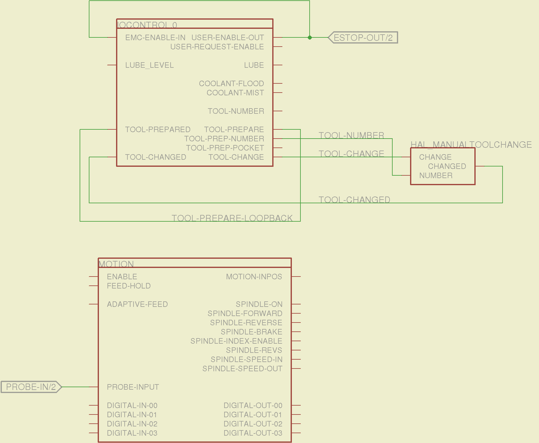
The tool height probe and manual tool change wiring:
Sherline Schematic – 3
I’m not convinced the Emergency Stop polarity is correct, but it matches what was in the original HAL file. As before, the Sherline driver box ignores that output, so none of that matters right now.
Four very similar pages define the XYZA step-and-direction generators. This is the X axis driver:
Sherline Schematic – 4
You can imagine what the next three pages for the YZA logic look like, right? There are also a few blank pages in the schematic, so the numbers jump abruptly.
The magic part of this is having Eagle manage all the tedious renumbering and counting. If you remember to adjust the name of the first module from, say, AXIS.1 to AXIS.0, then the rest get the proper numbers as you go along.
The remainder of the schematic implements the Joggy Thing’s logic, much as described there. I discovered, quite the hard way, that copy-and-pasting an entire schematic from elsewhere does horrible things to the device numbering, but I’m not sure how to combine two schematics to limit the damage. In any event, manually adjusting a few pages wasn’t the worst thing I’ve ever had to do; starting with a unified schematic should eliminate that task in the future.
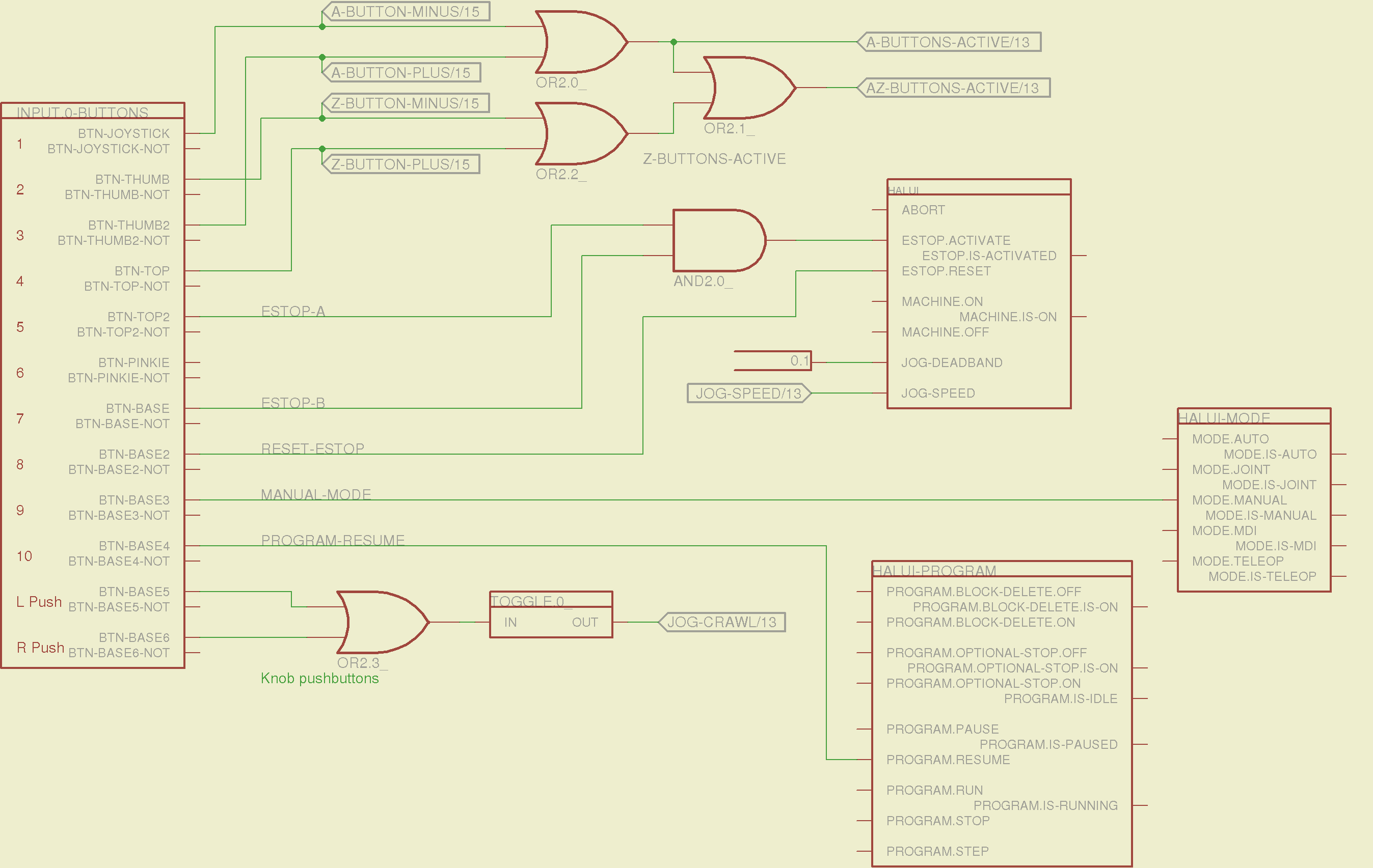
The miscellaneous buttons:
Sherline Schematic – 11
The joystick and hat values:
Sherline Schematic – 12
The joystick deadband logic now uses the (new with HAL 2.5, I think) input.n.abs-x-flat pins, which eliminated a tangle of window comparator logic.
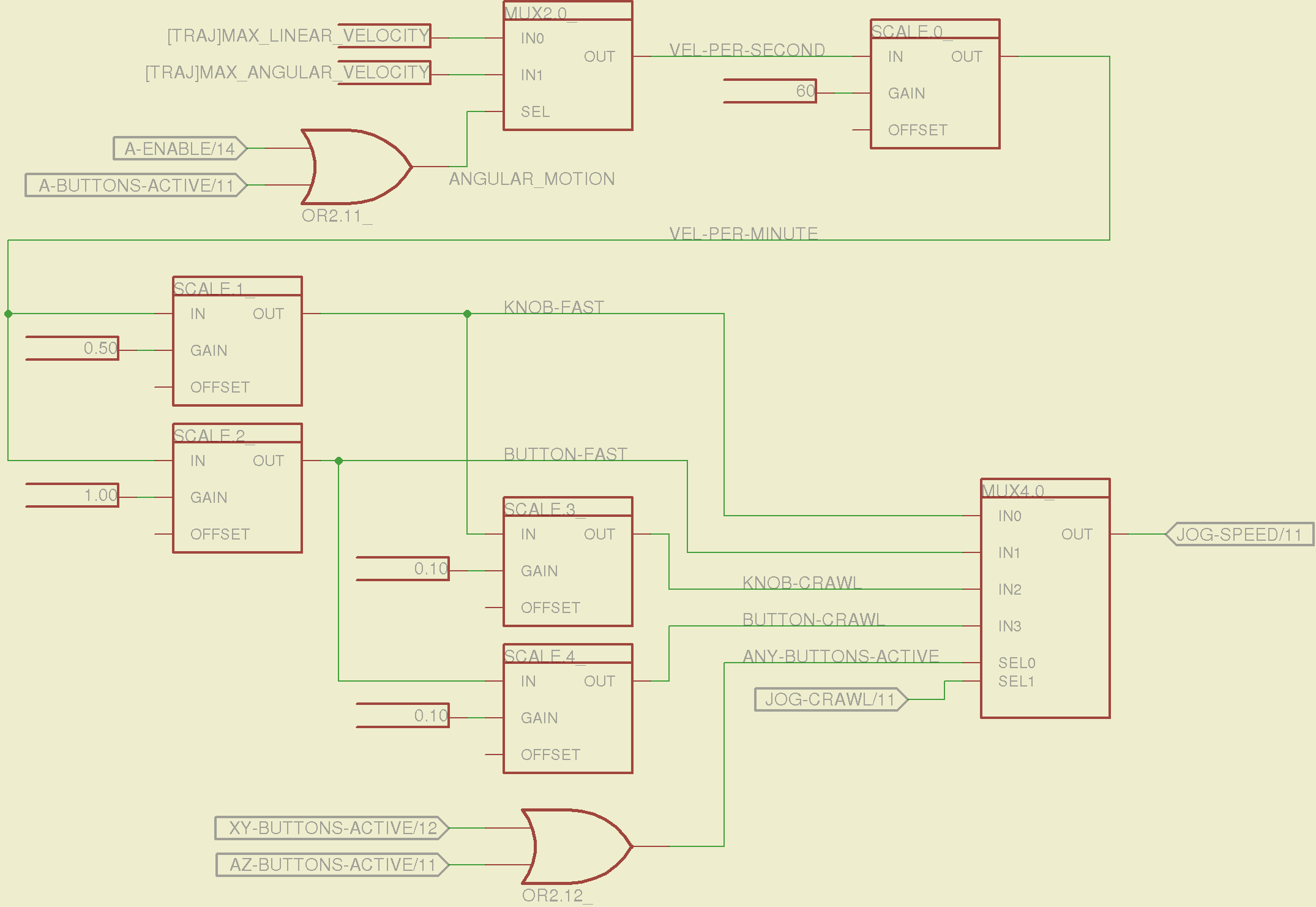
The jog speed adjustment logic that sets the fast and crawl speeds:
Sherline Schematic – 13
I should probably put the speed ratios in the INI file, but that’s in the nature of fine tuning.
The lockout logic that remembers which axis started moving first on a given joystick and locks out the other axis, which greatly simplifies jogging up to an edge without bashing into something else:
Sherline Schematic – 14
Combine all those signals into values that actually tell HAL to jog the axes:
Sherline Schematic – 15
The last page connects all the realtime function pins to the appropriate threads:
Sherline Schematic – 16
The LinuxCNC documentation diverges slightly from the implementation, but a few iterations resolved all the conflicts and had the additional benefit that I had to carefully think through what was actually going on.
A deep and sincere tip o’ the cycling helmet to the folks making LinuxCNC happen!
Although the Sherline mill doesn’t have more than a few minutes of power-on time with the new HAL file, the Joggy Thing behaves as it used to and the axes move correctly, so I think the schematic came out pretty close to the original HAL file.
The next step: draw a new schematic to bring up and exercise a different set of steppers…