Ed Nisley's Blog: Shop notes, electronics, firmware, machinery, 3D printing, laser cuttery, and curiosities. Contents: 100% human thinking, 0% AI slop.
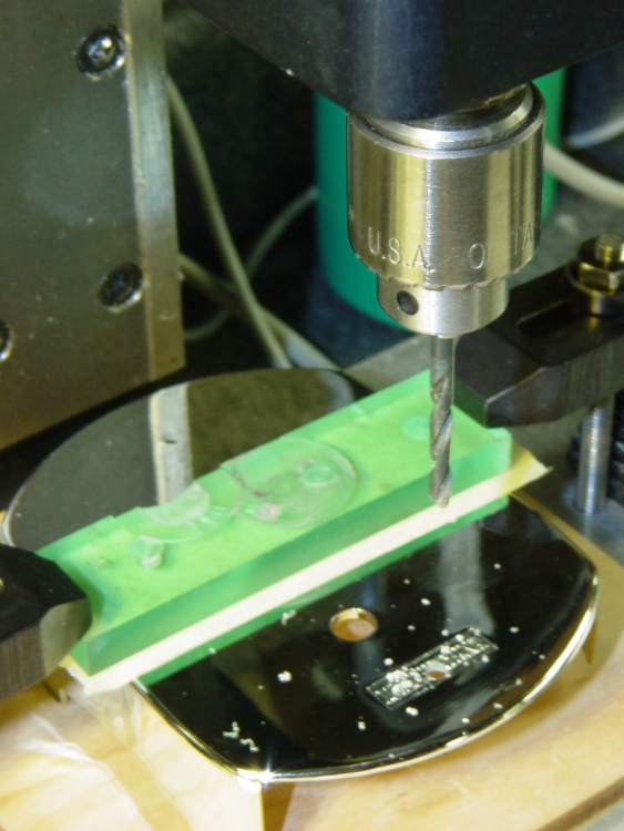
While pondering whether I should use the carcass of an old Dell PC to house the stepper drivers and control logic for the LinuxCNC M2 project, I bandsawed a scrap of aluminum sheet to about the right size. It had some truly nasty gouges and bonded-on crud, so I chucked up a wire brush cup in the drill press and had at it:
Machine jeweled baseplate
It’s obvious I haven’t done jeweling in a long time, isn’t it? Even a crude engine jeweling job spiffs things right up, though, even if a cough showcase job like this deserves straighter lines and more precise spacing. The aluminum sheet is far too large for the Sherline, which put CNC right out of consideration, and I’m not up for sufficient crank spinning on the big manual mill.
I match-marked mounting holes directly from the harvested motherboard and drilled them, whereupon I discovered that the aluminum is a dead-soft gummy alloy that doesn’t machine cleanly: it won’t become the final baseplate.
Memo to Self: Use the shop vacuum with the nozzle spinward of the brush, fool.
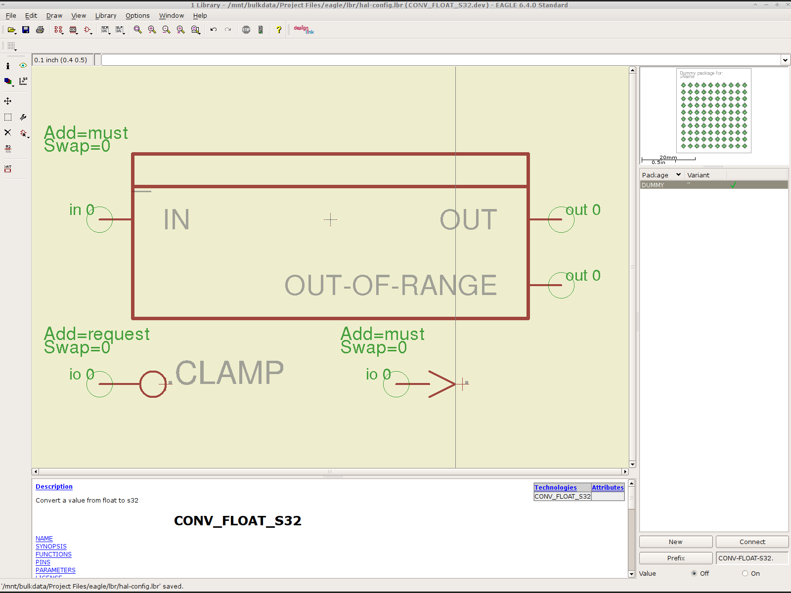
To that end, here’s a checklist for creating a new Eagle device corresponding to a HAL module.
Remember: although this process has a tremendous number of moving parts, you do it exactly once when you need a device that doesn’t already exist. After that, you just click to add an existing device to your schematic, wire it up, then the tedious write-only HAL overhead happens automagically.
Cross-check the documentation with the actual component code!
The man page lists the names, pins, parameters, and suchlike, but may have typos. This isn’t a criticism, it’s a fact of life.
Before investing a ton o’ time creating an Eagle device, load the module and find out what’s really there:
halrun
halcmd: loadrt conv_float_s32
halcmd: show all
Loaded HAL Components:
ID      Type  Name                                      PID   State
     4  RT    conv_float_s32                                  ready
     3  User  halcmd2395                                 2395 ready

Component Pins:
Owner   Type  Dir         Value  Name
     4  float IN              0  conv-float-s32.0.in
     4  s32   OUT             0  conv-float-s32.0.out
     4  bit   OUT         FALSE  conv-float-s32.0.out-of-range

... snippage ...

Parameters:
Owner   Type  Dir         Value  Name
     4  bit   RW          FALSE  conv-float-s32.0.clamp
     4  s32   RO              0  conv-float-s32.0.time
     4  s32   RW              0  conv-float-s32.0.tmax

... snippage ...

Exported Functions:
Owner   CodeAddr  Arg       FP   Users  Name
 00004  fc0a9000  fc0630b8  YES      0   conv-float-s32.0
... snippage ...
Achtung!
The module name uses underscores as separators: loadrt conv_float_s32
The function name uses h-y-p-h-e-n-s as separators: conv-float-s32.0
Unlike in the Linux kernel, the two characters are not equivalent
Add the HAL Module to the Conversion Script
The hal-write.ulp script contains a table of all the module names, so you must update the script in parallel with the hal-config.lbr Eagle library.
However, you can create an Eagle device that is not a HAL module by omitting it from the script. In that case, the Eagle device name will become part of the net names that define and interconnect the pins, but the script will not create a statement to load a module. For example, the hal_input userspace program creates a set of pins for each input device that start with input.n, but there’s no corresponding HAL module. I’ll put up an example of all this in a bit.
Create a Schematic Symbol
The name of the symbol is not critical: CONVERT.sym
use either dashes or hyphens as you prefer
The >NAME string must be on layer 95-Names
No need for a >VALUE string, but put it on layer 96-Values if present
HAL pins become symbol pins
Use the HAL pin name, with hyphens
Set Visibility to Pin
Set Direction to in / out / io to match the HAL description
Set Function to None to indicate an ordinary net connection
Verify the pins against the HAL device!
Create a HAL Schematic Device
The new device name must match the HAL module name, with underscores, as entered in the conversion script table
CONV_FLOAT_S32.dev
Set the Prefix to the HAL function name, plus a trailing period, with hyphens
CONV-FLOAT-S32.
Create the Description using copy-and-paste from the HTML source: use the man page in the LinuxCNC doc
Ctrl-U in Firefox reveals the HTML source, Ctrl-A and Ctrl-C, flip windows, then Ctrl-V
Delete all the boilerplate at the top, leave the centered Title, ditch the reference links
Add the symbol you created earlier or reuse an existing symbol
Set the symbol NAME to a single underscore: _
Change the Add level to must
Add a PIN_FUNCTION symbol to the device
Change the symbol name from G$1 (or whatever) to a single period: .
Change the Add Level to must
Add PIN_PARAMETER symbols as needed
Change the symbol name from G$1 (or whatever) to the parameter name preceded by a single period: .CLAMP
Change the Add Level to request
Change the Direction as needed
Add the DUMMY physical package, then connect all the pins to pads
Create a non-HAL Schematic Device
The new device name may be anything that’s not in the conversion script table
The Prefix must match the desired pin names, plus a trailing period. For hal_input pins:
INPUT.
Create the Description as above
Add the symbol you created earlier
Set the symbol NAME to a single underscore: _
Change the Add level to must
Do not add a PIN_FUNCTION symbol, because it has no corresponding module
Add PIN_PARAMETER symbols as needed
Change the symbol name from G$1 (or whatever) to the parameter name preceded by a single period: .CLAMP
Change the Add Level to request
Change the Direction as needed
Add the DUMMY physical package, then connect all the pins to pads
Devices may have multiple Symbols, with different Add Level options; can seems appropriate. As nearly as I can tell, you must name each Symbol as a suffix to the full name to differentiate them within the Device; I use a hyphen before the suffix, so that -KEYS generates INPUT.0-KEYS. Those suffixes don’t appear elsewhere in the generated HAL configuration file.
Save the library, update it in the schematic editor (Library → Update ...), and you’re set.
Although it’s tempting, do not include a version number in the library file name, because Eagle stores the file name inside the schematic file along with the devices from that file. As a result, when you bump the library version number and use devices from the new library file, the schematic depends on both library files and there’s no way within Eagle to migrate devices from one library to the other; you must delete the existing devices from the schematic and re-place them from the new library. Or you can do like I did: hand-edit the XML fields inside the library file.
Eagle HAL Device
You’ll almost certainly drive this procedure off the rails, so let me know what I’ve screwed up. It does, in fact, work wonderfully well and, as far as I’m concerned, makes HAL usable, if only because HAL is a write-only language to start with and now you need not read it to modify it.
Winding a slit ferrite toroid poses no challenge, so putting 25 turns of 26 AWG wire on it didn’t take long at all:
F50-61 toroid – 25 turns 26 AWG
However, a ferrite toroid doesn’t take kindly to being dropped and I figured that a slit toroid would crack under a stern look, so I decided to wrap some armor around it. A small squeeze bottle offered a cap just slightly larger than the winding, so I used that slitting saw to cut off a suitable ring. The first step was to grab it in the 3 jaw chuck and align its axis parallel to the spindle:
Aligning bottle cap in 3-jaw chuck
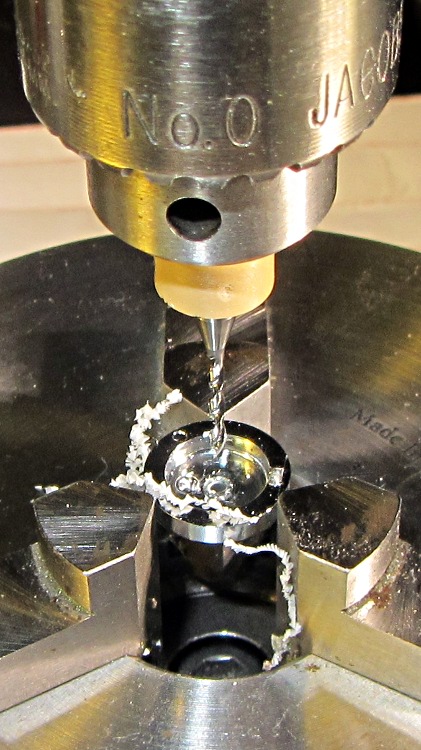
I wanted to cut off a slightly taller ring, but the clamping screw on the saw arbor just barely cleared the chuck for a 5 mm ring. I jogged around the chuck jaws to cut two slits in the cap that eventually joined near the back:
Slicing ring from bottle cap
That was about 1000 rpm, no coolant, and slow feed, but also a totally non-critical cut in plastic.
I put a snippet of foam rubber in the slot, put the ring on a Kapton-covered build platform from the Thing-O-Matic, filled it with hot-melt glue, gooshed the toroid in place, and waited for cooling. Trimming and cleaning out the slit produced a hideously ugly, but (I hope) much more durable assembly:
Slit ferrite toroid – with armor
I’m reasonably sure I didn’t crack the ferrite while cleaning out the slit; that hot-melt glue is tenaciously gummy stuff!
The object of the game: cut a slit into a ferrite toroid that will accommodate a Hall effect sensor. Those doodles showed that an FT50 (half-inch OD) toroid would be about right for the cheap AH49/EH49 Hall effect sensors on hand and those doodles shows that the permeability of the ferrite mix doesn’t make much difference. Not being quite sure how this would work out, I figured I’d start with the simplest possible setup and complexicate things until it worked…
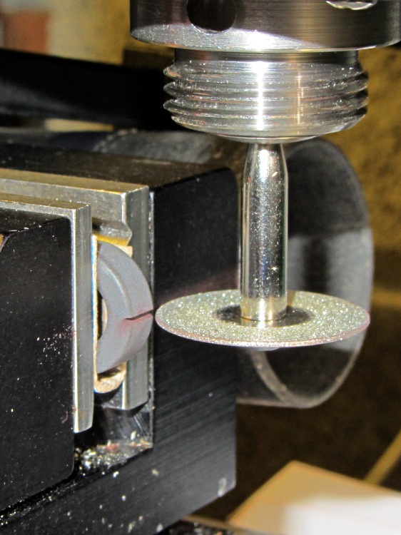
A fold of cereal box cardboard cushioned the brittle ferrite in the Sherline’s clamp and the vacuum hose in the background collects airborne grit. I touched off X=Y=Z=0 with the wheel at the center of the toroid’s equator:
Slitting ferrite toroid – first pass
The first pass went swimmingly, with the diamond wheel far more concentric than I expected, using manual jogging along a 0.5 mm deep cut. The wheel is slightly over 0.5 mm thick, measured on the grit, and showed no sign of strain on a 1 mm deep cut at 100 mm/min, so I used manual CNC to run the wheel back and forth along the cut.
After clearing the slot, I moved the wheel upward to + 0.5 mm, repeated the passes with a 1.5 mm depth of cut, then did the same at -0.5 mm. The end result was a nice slot with parallel sides:
Slitting ferrite toroid – complete
The actual gap measured 1.72 mm, not the 1.5 I wanted, which means the flux density will be lower than the previous calculations predict. Assuming the Z axis backlash compensation works as it should, then the kerf is 0.72 mm. Of course, that also assumes the arbor runs true and the wheel cuts symmetrically, neither of which I’d put (or, heck, have put) a lot of money behind. On the other paw, the sensors are 1.5 mm thick (just under the datasheet’s 1.6 mm spec), so +0.1 mm clearance on each side works a whole lot better for me than, say, -0.1 mm.
All in all, there was no excitement, no muss, no fuss, no chipping, no breakage:
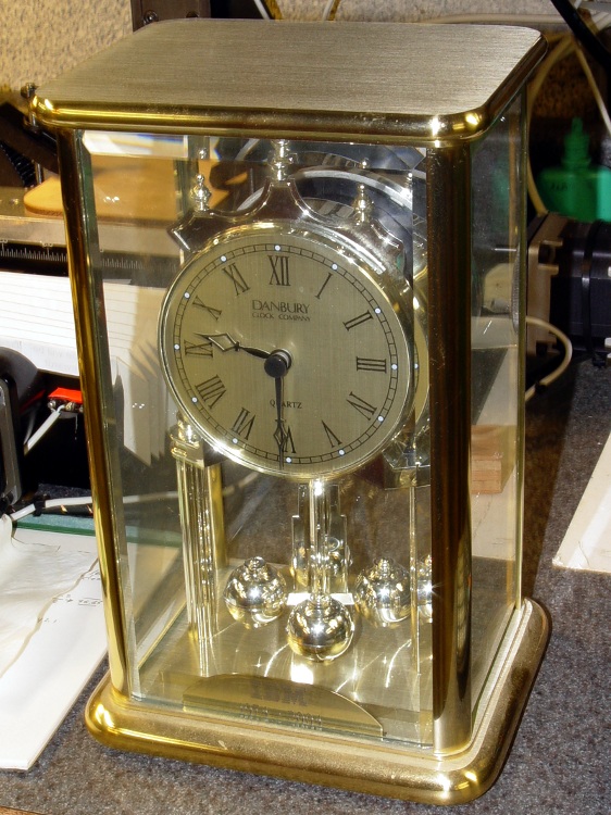
After 30 years, IBM gave Mary a commemorative clock, after which she promptly retired. Back in the day, they used to hand out Atmos clocks (admittedly, on more momentous occasions), but this isn’t one of those. In fact, although it appears to have a torsion pendulum, that’s a separate motor-driven foo-foo which we immediately turned off:
Janus Clock – front
It normally sits on the living room coffee table (which actually holds a myriad plants next to the front window) where, after we scrapped all the upholstered furniture, the two of us can’t both see the clock face from our chairs. Having a spare clock insert from that repair, we had the same bright idea at the same time: we need a clock with two faces! We came up with Janus independently…
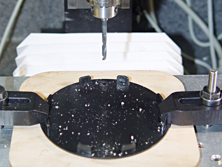
Despite its fancy appearance, the IBM clock consists mostly of brass and plastic, so I had no qualms about having my way with it in the shop. The new clock insert spanned the clock’s gilt plastic back cover, needing only a #1 drill hole for the adjustment stem, and exactly filled the available space between the back cover and the case. Both movements had enough interior clearance for 3-48 brass screw heads and nuts, so I eyeballed the right spots on the new cover, centered the Sherline spindle on the plate, and drilled two clearance holes 6 mm in from the edges on the vertical diameter:
Drilling clock insert cover
That put them 61.3 mm apart across the diameter, which would be awkward to duplicate by hand. Manual CNC makes it trivially easy to match-drill holes; I clamped down the gilt back cover from the IBM clock, aligned it to the table, located the center, and drilled two 3-48 clearance holes:
Drilling torsion clock cover
The glow from that polycarbonate packing block isn’t quite so nuclear in real life. The clamping force goes down the side panels of the cover, which had enough of a curve to be perfectly stable. Yes, I’m drilling into air, but came down real slow using the Joggy Thing and it was all good.
Assemble the two back covers (the holes matched perfectly), mark the adjustment stem hole, disassemble, hand-drill, reassemble, tighten nuts, and install:
Janus Clock – rear
It does look a bit lumpy from the side, but that’s just because I don’t have any gilding for the black tape wrap:
The plunger is basically a pin that eventually deforms the top of the switch membrane. Tee’s DSC-H1 had an exposed switch, although this picture shows that membrane was still in reasonably good condition:
Shutter Switch Closeup
My DSC-H5 has a thin black protective disk atop the switch, but the disk wasn’t particularly protective and developed a dimple that held the contacts closed even with the shutter button released (which is why I’m tearing the camera apart in the first place):
DSC-H5 Shutter Switch – dimpled protector
The C-clip around the plunger is now plastic, rather than metal, making it less likely to erode the thin plastic shaft. Pulling the clip off while holding the button down releases all the parts:
DSC-H5 Shutter Button – components
A few measurements from an intact shutter button, which may come in handy if you don’t have one:
DSC-H5 Shutter Button – plunger measurements
Mount three-jaw chuck on the Sherline table, laser-align chuck to spindle, grab shutter button by its shaft in a Jacobs chuck, grab shutter button in three-jaw chuck, release from Jacobs chuck:
DSC-H5 Shutter Button – in Sherline chuck
That’s not particularly precise, but it’s close enough for this purpose. I used manual jogging while testing the fit with a paper shim until all three jaws had the same clearance, then tightened the jaws.
I nicked the plunger at its base with a flush-cutting diagonal cutter, snapped off the plunger, and drilled a #56 hole through the button:
DSC-H5 Shutter Button – cap drilling
For reasons that made sense at the time, I repaired Tee’s DSC-H1 with a 1-72 brass screw. This time, I used an 0-80 (which I learned as ought-eighty, if you’re wondering about the indefinite article) screw and nut, because the screw head fit neatly into the bezel recess and I had a better idea of how to smooth out the threads.
This being plastic, I used the chuck to hold the tap in the proper alignment, then turned the tap through by finger pressure. This trial fit showed it worked:
DSC-H5 Shutter Button – 0-80 screw
Milling the nut down to a 2.8 mm cylinder required the usual manual CNC, with repeated iterations of this chunk of code in the MDI panel:
The 2.8 in the first line is the current OD and the 3.11 is the measured diameter of the 1/8 inch end mill. I started from a 5.0 mm OD that just kissed the nut, then worked inward by 0.2 mm at a time for very shallow 0.1 mm cuts:
DSC-H5 Shutter Button – 0-80 nut milling
The alert reader will notice, as did I, that the head isn’t quite centered: the cut trimmed the left side and left the right untouched, with an offset far larger than the centering error. As nearly as I can tell, the heads of those screws aren’t exactly centered on their threaded shafts, but the final result fixed that… and the overall error is a few tenths of a millimeter = maybe 10 mils, tops, so it’s no big deal.
With all that in hand, I applied a very very thin layer of epoxy to fill the threads below the now-cylindrical nut and convert the screw into a rod:
DSC-H5 Shutter Button – 0-80 plunger
My original intent was to use the screw head as-is atop the PET shield (per those instructions) on the switch membrane, but after reassembling enough of the camera to try that out, it didn’t work correctly: the half-pressed switch didn’t activate reliably before the full-pressed switch tripped.
The PET shield I used came from the side of a 1 liter soda bottle and turned out to be 0.27 mm thick:
DSC-H5 Shutter Switch – cover removed
I think the PET shield would work with the original plunger shape concentrating the force in the middle of the shield, but the nice flat screw head spreads the force out over a wider area. As a result, the force required to close the half-pressed switch contacts was roughly the same as that required to close the full-pressed contacts; remember the nub on the bottom of the black plastic tray concentrates the force in the middle of the full-pressed switch membrane.
So I removed the PET shield, added a dot of epoxy to fill the screw slot and compensate for the missing shield thickness, then filed a flat to make a nice pad:
DSC-H5 Shutter Button – epoxy on plunger
Reassembling the camera once more showed it worked exactly the way it should. In fact, the button seems more stable than the OEM version, probably because the slightly enlarged plunger shaft fits better in the bezel. Too bad about those scuffs on that nice shiny button dome, though:
DSC-H5 – repaired shutter button
Tossing the leftover parts seems entirely appropriate…
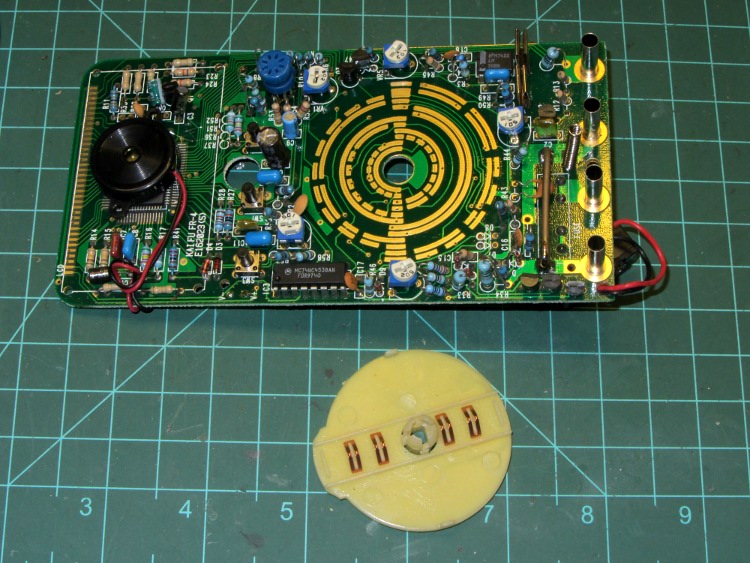
One of my multimeters began reporting bogus values that improved by working the range switch back-and-forth, which suggested the switch contacts need cleaning. Taking the meter apart was easy, right up to the point where I removed the range switch from the PCB by compressing the four locking tabs on the central shaft:
Multimeter range selector switch
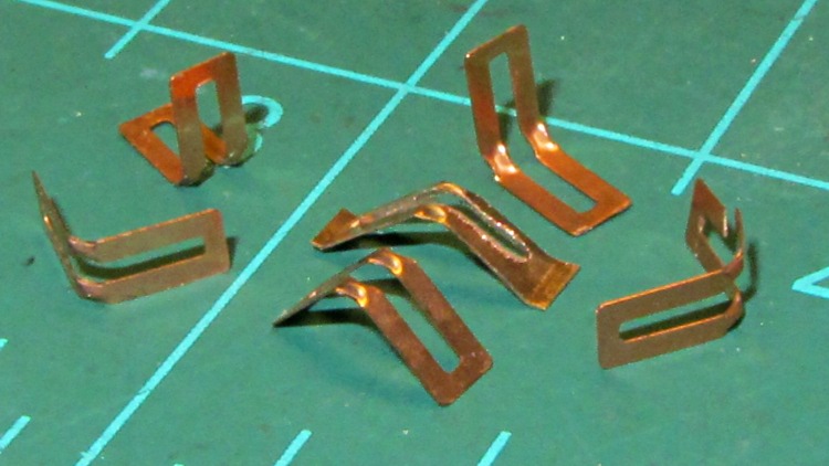
Just before taking that picture, the switch launched half a dozen spring contacts across the bench, my shirt, and the floor… I recovered four for the picture and later found a fifth smashed on the floor, but the last contact remains AWOL.
The contact in the middle, the oddly shaped one with small tabs on the ends, is a prototype replacement conjured from 6 mil phosphor bronze stock:
Multimeter range switch contacts
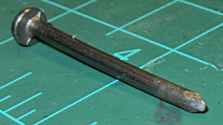
The little domes ensure a good sliding surface, but require two bends in the middle of the contact and some way to shape the metal into a dome. After a few experiments, I filed the end of a nail into a rounded chisel that worked pretty well:
DMM switch contact punch
The original contacts came from 3.5 mil stock and have considerably more flex; 6 mil stock is what I have.
I think I should make half a dozen contact springs to replace the entire set, a task requiring more time than I have right now. For the record, the overall process goes like this:
lay out overall shape, slightly longer than needed
cut center opening with abrasive wheel
cut out contact
punch contact domes (from back = dimples)
bend to shape
trim ends to length (not done in picture)
dress raw edges (not done in picture)
Given the number of parts and the fiddly accuracy required to make the slot, this might be a good job for the Sherline, although clamping each little proto-spring down while getting the abrasive wheel in there seems daunting.
Perhaps cutting the slots and punching the dimples would work better before cutting out the contacts, with a sheet clamped on four sides? The center will be floppy, what with all the slots, but grinding slots on the middle contacts first might be helpful. Would adhesive under the sheet to hold down the middle gunk up the abrasive wheel?