Ed Nisley's Blog: Shop notes, electronics, firmware, machinery, 3D printing, laser cuttery, and curiosities. Contents: 100% human thinking, 0% AI slop.
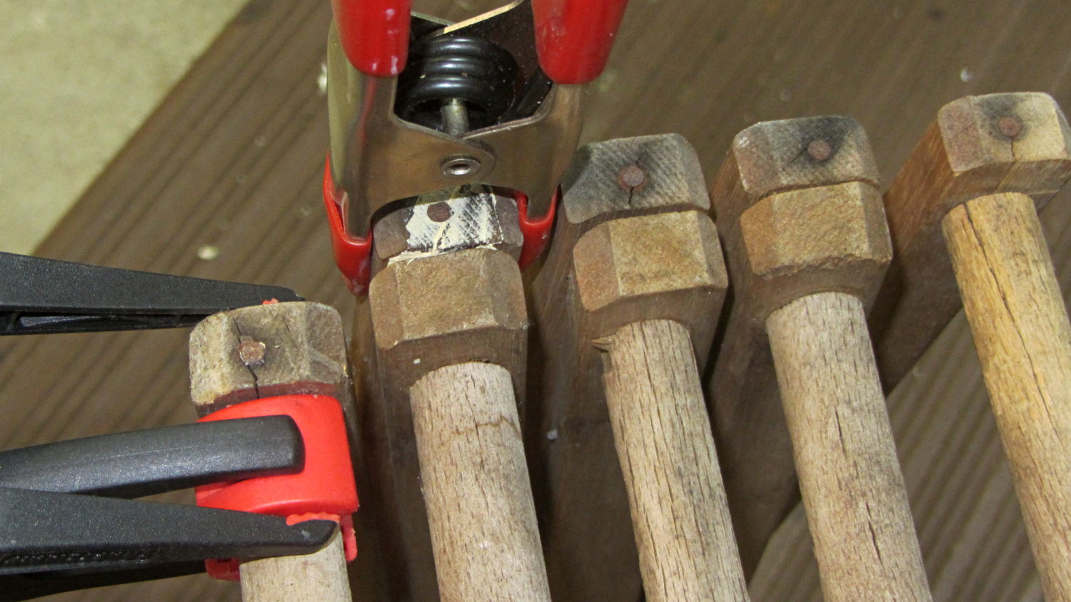
Despite having sworn a mighty oath to the contrary, I found myself doing this again:
Clothes Rack – end clamp
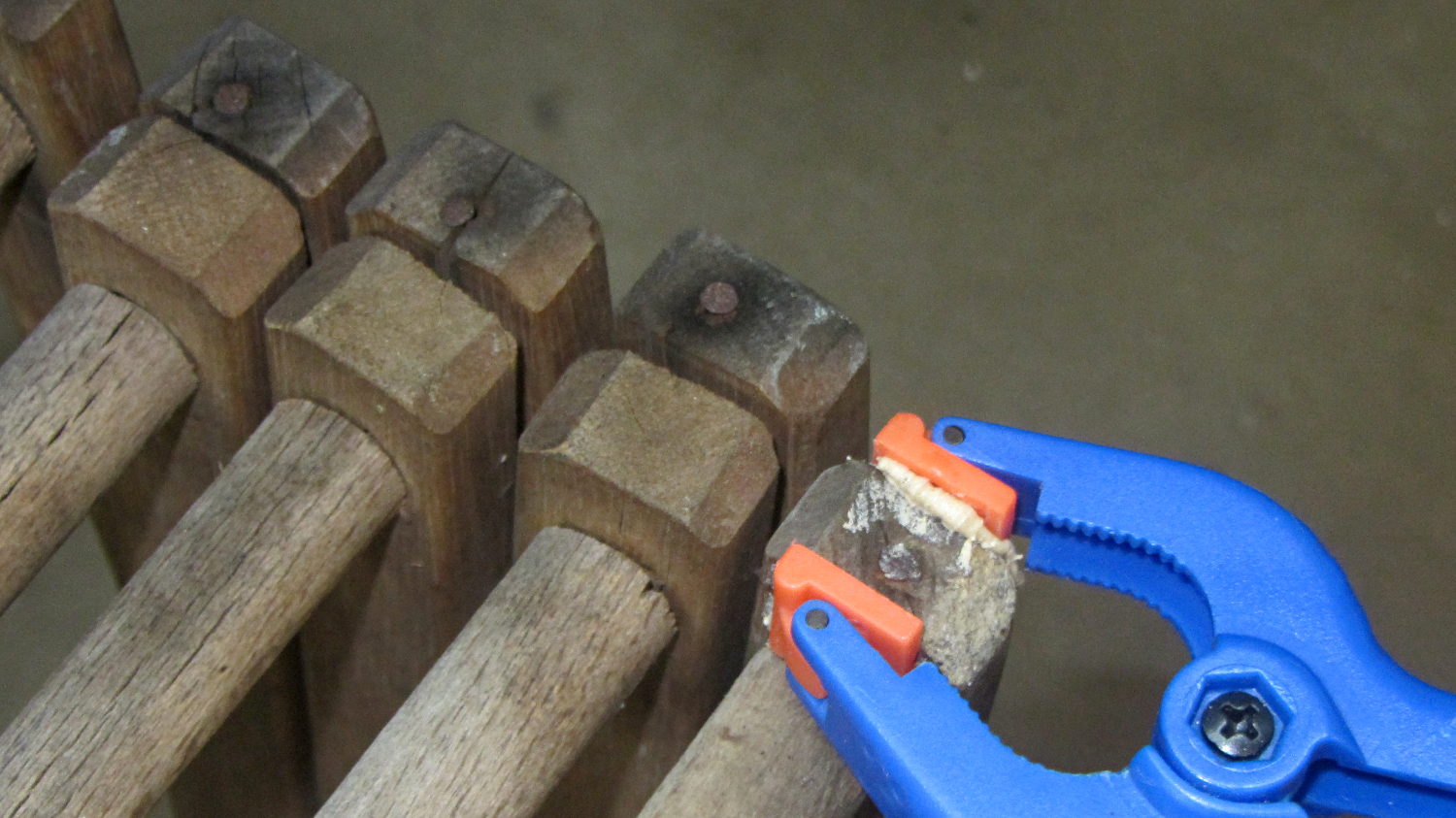
A strut on the other end of the dowel split across its face:
Clothes Rack – split clamp
The white stuff is wood-filled epoxy, normally used to repair rotted wood, left over from another project. I’ll claim this tests its mechanical strength against peeling forces.
Easily determined by inspection: a sensible person would toss the rack, but …
The two knockoff Neopixeltestfixtures went dark while their USB charger accompanied me on a trip, so they spent a few days at ambient basement conditions. When I plugged them back into the charger, pretty much the entire array lit up in pinball panic mode:
WS2812 LED – test fixture multiple failures
Turns out three more WS2812 chips failed in quick succession. I’ve hotwired around the deaders (output disconnected, next chip input in parallel) and, as with the other zombies, they sometimes work and sometimes flicker. That’s five failures in 28 LEDs over four months, a bit under 3000 operating hours.
For lack of a better explanation: the cool chips pulled relatively moist air through their failed silicone encapsulation, quietly rotted out in the dark, then failed when reheated. After they spend enough time flailing around, the more-or-less normal operating temperatures drives out the moisture and they (sometimes) resume working.
Remember, all of them passed the Josh Sharpie Test, so you can’t identify weak ones ahead of time.
I wired a resistive joystick to the knockoff Nano controlling the crystal tester and connected the button to an analog input because I have a lot of those left over and why not. Unfortunately, the ADC returned a sequence of random-ish numbers indicating the button didn’t have a pullup to +5 V.
One might be forgiven for assuming the pads marked R5 would hold such a pullup resistor, had the joystick not been relentlessly cost-reduced:
Keyes resistive joystick – R5 location
One would, of course, be completely wrong.
Having been around this blockseveral times, I measured the pad-to-pin resistances and found R5 firmly affixed to the GND and +5V pins, with the SW (a.k.a. button) pin floating free. Pressing the joystick hat closes the switch next to R5, thereby connecting the SW pin to GND.
Baffles me. Maybe a fresh intern did the PCB layout and just misplaced the resistor?
So I soldered an ordinary resistor (*) between the +5 V and SW pins:
Keyes resistive joystick – button pullup
Now it works just as it should.
(*) For long-lost reasons, I have a zillion 12.4 kΩ 1% resistors appearing in place of simple 10 kΩ resistors.
The plotter I received works beautifully, except that the carousel doesn’t rotate. I found a YouTube video showing a 7475a running with the cover off, and there’s a little plastic piece – it looks like a teardrop – that advances the carousel, and is apparently part of the carousel motor assembly. Mine is missing that piece …
The keyword is Geneva drive, a wonderfully simple technique to convert one rotation of the stepper motor into 1/6 turn of the pen carousel, with no need for fancy sensors.
Back in the day, you could get the entire Pen Carousel Housing Assembly w/ Motor (PN 07475-60175) as a unit and the Carousel Motor Only(PN 3140-0687) as a separate thing, but not the Geneva drive wheel:
HP7475A Carousel – Geneva drive cam
The cam’s drive wheel end (in inches, because early 1980s):
0.25 thick overall
0.10 thick plate under pin end
1.09 OD – rounded end
The pin sticking up from the cam:
0.154 OD (or fit to slot?)
0.16 tall (above base plate)
I have no good (i.e., easy + accurate) way to measure the distance from the motor shaft to the pin, but I doubt it’s critical. As long as the pin doesn’t quite whack the hub end of the slot, it’s all good:
HP7475A Carousel – cam driving
The 0.10 plate + 0.16 pin height don’t quite add up to the 0.25 overall measurement, but that’s certainly measurement error. I’d round the pin length downward and carve the drive from a 1/4 inch sheet.
A 3D printed part would probably work, apart from the accuracy required to fit the D-shaped motor shaft. Perhaps a round hole, reamed to fit the shaft, carefully aligned / positioned, with epoxy filling the D-shaped void, would suffice. A dent in the round hole would give the epoxy something to grab.
I’d be sorely tempted to use an actual metal / plastic rod for the pin, rather than depend on a stack of semi-fused plastic disks. The pin must withstand hitting the end of the “missing” slot during the power-on indexing rotation, because turning the carousel isn’t quite a non-contact sport. Normally, though, it enters the end of the slot without much fuss:
HP7475A Carousel – cam engaging
The blocked slot sits at the bottom of that picture, with a small locating pin sticking upward just above the circular feature at the end of the arm: we’re seeing the negative of a plug inserted into the original injection mold.
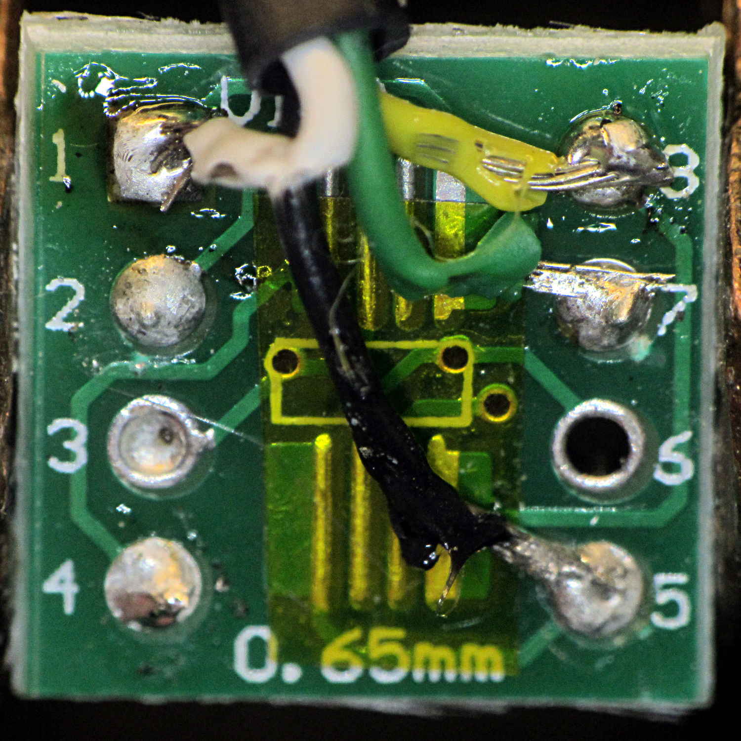
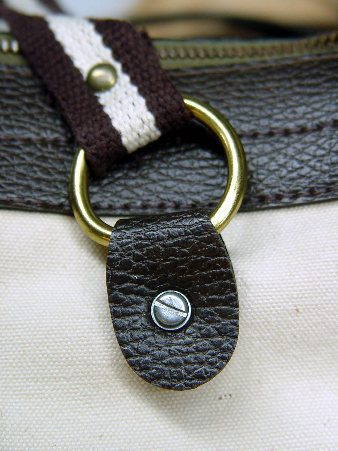
After hairballing an LM75A I²C temperature sensor to verify at least one of the eBay lot worked, a bag of SOIC-to-DIP space transformers arrived, so I soldered up another LM75A:
LM75A on DIP8 adapter – top
The SOIC chip pattern sits at right angles to the DIP pins, which took some getting used to.
The slightly defocused wire connecting pin 4 (on the IC) to pins 5, 6, and 7 (on the PCB) selects address 0x48.
So I flipped it over, soldered four wires (+5 V, GND, SDA, SCL) to the numbered pins on bottom of the board, made up a little header for the other end, wired a socket strip on the crystal tester board, plugged it in, and … nothing worked.
Turns out that the other side of the board carries a TSSOP pattern, which I’d neatly masked off with a snippet of Kapton tape, surrounded by eight numbered pins. Of course, those pin numbers correspond to the TSSOP pattern facing you, so they’re mirror-imaged for the SOIC pattern on the other side.
Soooo, the proper wiring for the SOIC pattern as seen from the TSSOP side has the pin numbers exactly bass-ackwards:
LM75A on DIP8 adapter – bottom
The insulation looked a lot better the first time I soldered the wires to the PCB. Honest.
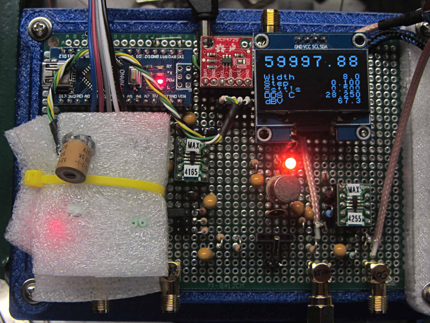
Anyhow, when correctly wired, the LM75A worked as it should:
LM75A Temperature Sensor – installed
It’s snuggled chip-down against the top of the 125 MHz oscillator can, with a dab of heatsink compound improving their thermal bond and a yellow cable tie around the foam holding them together. The socket header is wired pin-for-pin to the DAC I²C socket directly above it.
The OLED temperature display shows 28.250 °C, because the oscillator just started up in a cool basement. It’ll eventually settle around 39-ish °C, where its output should be pretty close to the 125 MHz – 344 Hz value hardcoded into the source.
Oh, that’s a 3 mm amber LED next to the relay can: much less glaring than the white LED, no matter what it looks like here.
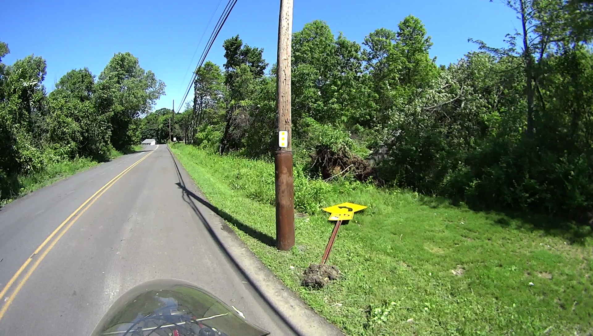
The National Weather Service in coordination with Dutchess County Emergency Management officials, have confirmed a brief touchdown of a tornado on May 31. The tornado path began near the intersection of Maloney Road and Route 376. The tornado traveled due east along and just north of Maloney Road for approximately 1.25 miles before dissipating. Damage included numerous snapped hardwood and softwood trees and the roof lifted off a shed.
Both of Mary’s gardens suffered beatdowns, with the Vassar Farm plot pretty thoroughly pulverized by marble-size hail; she’s not in a good mood right now.
The DPW crews had plenty on their to-do list, but that branch was gone a day later.
Update: The top of the barely visible tree in the second picture just kissed the trail fence, but a much larger tree smashed both fences on its way across the trail:
Wappinger Tornado – Rail Trail S of Maloney – 2017-06-04
If you need some firewood, maybe you can make a deal …