Given that I no longer trust any of the knockoff Neopixels, I wired the remaining PCB panel into a single hellish test fixture:
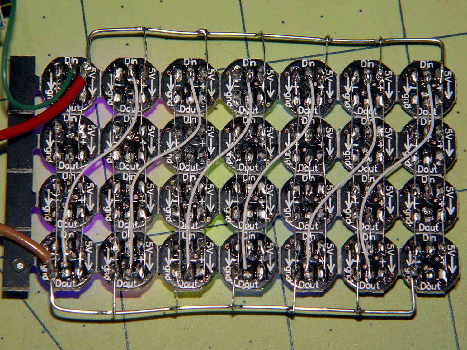
The 22 AWG wires deliver +5 V and Common, with good old-school Wire-Wrap wire passing to the four LEDs betweem them. The data daisy chain snakes through the entire array.
It seems only fitting to use a knockoff Arduino Nano as the controller:
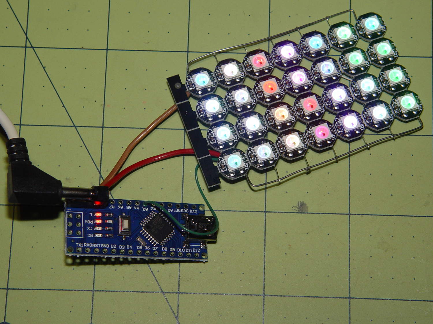
The code descends from an early version of the vacuum tube lights, gutted of all the randomizing and fancy features. It updates the LEDs every 20 ms and, with only 100 points per cycle, the colors tick along fast enough reassure you (well, me) that the thing is doing something: the pattern takes about 20 seconds from one end of the string to the other.
At full throttle the whole array draws 1.68 A = 60 mA × 28 with all LEDs at full white, which happens only during the initial lamp test and browns out the supply (literally: the blue LEDs fade out first and produce an amber glow). The cheap 5 V 500 mA power supply definitely can’t power the entire array at full brightness.
The power supply current waveform looks fairly choppy, with peaks at the 400 Hz PWM frequency:
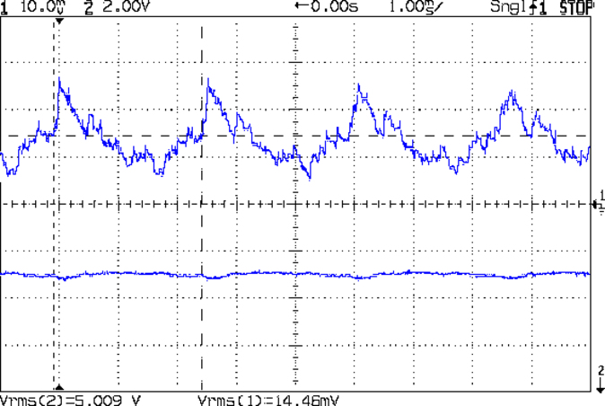
With the Tek current probe set at 200 mA/div, the upper trace shows 290 mA RMS. That’s at MaxPWM = 127, which reduces the average current but doesn’t affect the peaks. At full brightness the average current should be around 600 mA, a tad more than the supply can provide, but maybe it’ll survive; the bottom trace shows a nice average, but the minimum hits 4.6 V during peak current.
Assuming that perversity will be conserved as usual, none of the LEDs will fail for as long as I’m willing to let them cook.
The Arduino source code as a GitHub Gist:
| // WS2812 LED array exerciser | |
| // Ed Nisley – KE4ANU – February 2017 | |
| #include <Adafruit_NeoPixel.h> | |
| //———- | |
| // Pin assignments | |
| const byte PIN_NEO = A3; // DO – data out to first Neopixel | |
| const byte PIN_HEARTBEAT = 13; // DO – Arduino LED | |
| //———- | |
| // Constants | |
| #define UPDATEINTERVAL 20ul | |
| const unsigned long UpdateMS = UPDATEINTERVAL – 1ul; // update LEDs only this many ms apart minus loop() overhead | |
| // number of steps per cycle, before applying prime factors | |
| #define RESOLUTION 100 | |
| // phase difference between LEDs for slowest color | |
| #define BASEPHASE (PI/16.0) | |
| // LEDs in each row | |
| #define NUMCOLS 4 | |
| // number of rows | |
| #define NUMROWS 7 | |
| #define NUMPIXELS (NUMCOLS * NUMROWS) | |
| #define PINDEX(row,col) (row*NUMCOLS + col) | |
| //———- | |
| // Globals | |
| // instantiate the Neopixel buffer array | |
| Adafruit_NeoPixel strip = Adafruit_NeoPixel(NUMPIXELS, PIN_NEO, NEO_GRB + NEO_KHZ800); | |
| uint32_t FullWhite = strip.Color(255,255,255); | |
| uint32_t FullOff = strip.Color(0,0,0); | |
| struct pixcolor_t { | |
| byte Prime; | |
| unsigned int NumSteps; | |
| unsigned int Step; | |
| float StepSize; | |
| float TubePhase; | |
| byte MaxPWM; | |
| }; | |
| // colors in each LED | |
| enum pixcolors {RED, GREEN, BLUE, PIXELSIZE}; | |
| struct pixcolor_t Pixels[PIXELSIZE]; // all the data for each pixel color intensity | |
| unsigned long MillisNow; | |
| unsigned long MillisThen; | |
| //– Figure PWM based on current state | |
| byte StepColor(byte Color, float Phi) { | |
| byte Value; | |
| Value = (Pixels[Color].MaxPWM / 2.0) * (1.0 + sin(Pixels[Color].Step * Pixels[Color].StepSize + Phi)); | |
| // Value = (Value) ? Value : Pixels[Color].MaxPWM; // flash at dimmest points | |
| // printf("C: %d Phi: %d Value: %d\r\n",Color,(int)(Phi*180.0/PI),Value); | |
| return Value; | |
| } | |
| //– Helper routine for printf() | |
| int s_putc(char c, FILE *t) { | |
| Serial.write(c); | |
| } | |
| //—————— | |
| // Set the mood | |
| void setup() { | |
| pinMode(PIN_HEARTBEAT,OUTPUT); | |
| digitalWrite(PIN_HEARTBEAT,LOW); // show we arrived | |
| Serial.begin(57600); | |
| fdevopen(&s_putc,0); // set up serial output for printf() | |
| printf("WS2812 array exerciser\r\nEd Nisley – KE4ZNU – February 2017\r\n"); | |
| /// set up Neopixels | |
| strip.begin(); | |
| strip.show(); | |
| // lamp test: run a brilliant white dot along the length of the strip | |
| printf("Lamp test: walking white\r\n"); | |
| strip.setPixelColor(0,FullWhite); | |
| strip.show(); | |
| delay(250); | |
| for (int i=1; i<NUMPIXELS; i++) { | |
| digitalWrite(PIN_HEARTBEAT,HIGH); | |
| strip.setPixelColor(i-1,FullOff); | |
| strip.setPixelColor(i,FullWhite); | |
| strip.show(); | |
| digitalWrite(PIN_HEARTBEAT,LOW); | |
| delay(250); | |
| } | |
| strip.setPixelColor(NUMPIXELS – 1,FullOff); | |
| strip.show(); | |
| delay(250); | |
| // fill the array, row by row | |
| printf(" … fill\r\n"); | |
| for (int i=0; i < NUMROWS; i++) { // for each row | |
| digitalWrite(PIN_HEARTBEAT,HIGH); | |
| for (int j=0; j < NUMCOLS; j++) { | |
| strip.setPixelColor(PINDEX(i,j),FullWhite); | |
| strip.show(); | |
| delay(100); | |
| } | |
| digitalWrite(PIN_HEARTBEAT,LOW); | |
| } | |
| // clear to black, column by column | |
| printf(" … clear\r\n"); | |
| for (int j=NUMCOLS-1; j>=0; j–) { // for each column | |
| digitalWrite(PIN_HEARTBEAT,HIGH); | |
| for (int i=NUMROWS-1; i>=0; i–) { | |
| strip.setPixelColor(PINDEX(i,j),FullOff); | |
| strip.show(); | |
| delay(100); | |
| } | |
| digitalWrite(PIN_HEARTBEAT,LOW); | |
| } | |
| delay(1000); | |
| // set up the color generators | |
| MillisNow = MillisThen = millis(); | |
| printf("First random number: %ld\r\n",random(10)); | |
| Pixels[RED].Prime = 11; | |
| Pixels[GREEN].Prime = 7; | |
| Pixels[BLUE].Prime = 5; | |
| printf("Primes: (%d,%d,%d)\r\n",Pixels[RED].Prime,Pixels[GREEN].Prime,Pixels[BLUE].Prime); | |
| unsigned int PixelSteps = (unsigned int) ((BASEPHASE / TWO_PI) * | |
| RESOLUTION * (unsigned int) max(max(Pixels[RED].Prime,Pixels[GREEN].Prime),Pixels[BLUE].Prime)); | |
| printf("Pixel phase offset: %d deg = %d steps\r\n",(int)(BASEPHASE*(360.0/TWO_PI)),PixelSteps); | |
| Pixels[RED].MaxPWM = 127; | |
| Pixels[GREEN].MaxPWM = 127; | |
| Pixels[BLUE].MaxPWM = 127; | |
| for (byte c=0; c < PIXELSIZE; c++) { | |
| Pixels[c].NumSteps = RESOLUTION * (unsigned int) Pixels[c].Prime; | |
| Pixels[c].Step = (3*Pixels[c].NumSteps)/4; | |
| Pixels[c].StepSize = TWO_PI / Pixels[c].NumSteps; // in radians per step | |
| Pixels[c].TubePhase = PixelSteps * Pixels[c].StepSize; // radians per tube | |
| printf("c: %d Steps: %5d Init: %5d",c,Pixels[c].NumSteps,Pixels[c].Step); | |
| printf(" PWM: %3d Phi %3d deg\r\n",Pixels[c].MaxPWM,(int)(Pixels[c].TubePhase*(360.0/TWO_PI))); | |
| } | |
| } | |
| //—————— | |
| // Run the mood | |
| void loop() { | |
| MillisNow = millis(); | |
| if ((MillisNow – MillisThen) > UpdateMS) { | |
| digitalWrite(PIN_HEARTBEAT,HIGH); | |
| unsigned int AllSteps = 0; | |
| for (byte c=0; c < PIXELSIZE; c++) { // step to next increment in each color | |
| if (++Pixels[c].Step >= Pixels[c].NumSteps) { | |
| Pixels[c].Step = 0; | |
| printf("Color %d steps %5d at %8ld delta %ld ms\r\n",c,Pixels[c].NumSteps,MillisNow,(MillisNow – MillisThen)); | |
| } | |
| AllSteps += Pixels[c].Step; // will be zero only when all wrap at once | |
| } | |
| if (0 == AllSteps) { | |
| printf("Grand cycle at: %ld\r\n",MillisNow); | |
| } | |
| for (int k=0; k < NUMPIXELS; k++) { // for each pixel | |
| byte Value[PIXELSIZE]; | |
| for (byte c=0; c < PIXELSIZE; c++) { // … for each color | |
| Value[c] = StepColor(c,-k*Pixels[c].TubePhase); // figure new PWM value | |
| // Value[c] = (c == RED && Value[c] == 0) ? Pixels[c].MaxPWM : Value[c]; // flash highlight for tracking | |
| } | |
| uint32_t UniColor = strip.Color(Value[RED],Value[GREEN],Value[BLUE]); | |
| strip.setPixelColor(k,UniColor); | |
| } | |
| strip.show(); | |
| MillisThen = MillisNow; | |
| digitalWrite(PIN_HEARTBEAT,LOW); | |
| } | |
| } |

Comments
10 responses to “Cheap WS2812 LEDs: Test Fixture”
That wiring is visually attractive, but it makes me think they should have integrated it into the PCB, so they’re all connected before they’re snapped apart. And I like the “conservation of perversity” phrase – I usually go with “the general cussedness of things”.
I was mildly surprised that the panel didn’t include test wiring, too. I can’t imagine unit-testing each LED on the assembled panels would be cost-effective; maybe they just trust that nothing can go gnorw.
The adafruit datasheet is badly formatted (top of page 3, header at the bottom of page 2).
Click to access WS2812.pdf
The absolute max is in there. Vcc (abs-max) is 6~7V for the supply and Vdd (abs-max) is also 6~7V for the LEDs.
We used to specify a single voltage for absolute max–can’t say I’m fond of a range. Where I worked (usually in bipolar facilities, though we were doing MOS before the dot-com V1.0 collapse), if you stayed below the abs-max supply, the part would survive, but Thar be Dragons if you go above it. I also get nervous about running afoul of power dissipation if running above the nominal Vxx maxima (5.5V here). Usually not so bad in a room temp ambient, but the magic smoke can be let out when you go above the max for a while.
Oh, I couldn’t of been bothered to go look for the datasheet. I did say a “quick” look though :)
Well, as it turns out, I was wrong: the first LED failed after a few power-on days.
No need for extreme measures: they’ll fail all by themselves!
[…] Mounting the ungainly WS2812 LED test fixture seemed like a Good Idea to keep the electricity out of the usual conductive litter: […]
[…] the WS2812 test fixture neatly mounted, I plugged it into a six-port USB charger allegedly capable of supplying 2.4 A per […]
[…] Wiring up a 5×5 panel went as before: […]
[…] second WS2812 RGB LED in the test fixture […]