A strip of NXP (née Philips plus Freescale, including the part of Motorola that didn’t become ON) LM75A I²C temperature sensors arrived from beyond the horizon. To see if they worked, I soldered thin wires directly to the SO-8 pins, entombed it in Kapton tape to prevent spitzensparken, and jammed it under the foam insulation atop the AD9850 DDS module:

This turns out to be easier than screwing around with thermistors, because the chip reports the temperature directly in Celcius with ⅛ °C resolution. Classic LM75 chips from National (now absorbed by TI) had ½ °C resolution, but the datasheet shows the bits have an easily extensible format:

Huh. Fixed-point data, split neatly on a byte boundary. Who’d’a thunk it?
There’s a standard Arduino library using, naturally enough, floating point numbers, but I already have big fixed point numbers lying around and, with the I²C hardware up & running from the X axis DAC and OLED display, this was straightforward:
Wire.requestFrom(LM75_ADDR,2);
Temp.fx_32.high = Wire.read();
Temp.fx_32.low = (uint32_t)Wire.read() << 24;
PrintFixedPtRounded(Buffer,Temp,3);
u8x8.drawString(0,ln,"DDS C          ");
u8x8.drawString(16-strlen(Buffer),ln,Buffer);
printf(",%s",Buffer);
ln += 1;
The next-to-last line squirts the temperature through the serial port to make those nice plots.
Casually ignoring all I²C bus error conditions will eventually lead to heartache and confusion. In particular, the Basement Laboratory temperature must never fall below 0 °C, because I just plunk the two’s-complement temperature data into an unsigned fixed point number.
Which produces the next-to-bottom line:
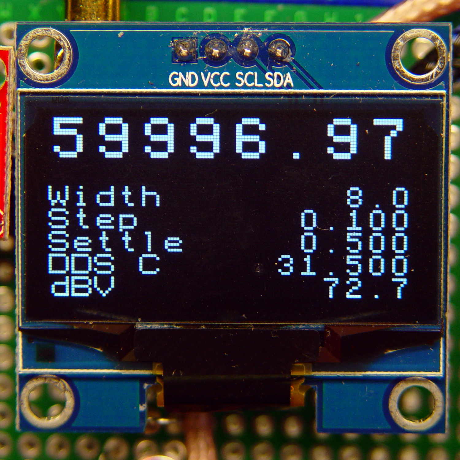
Alas, the u8x8 font doesn’t include a degree symbol.
Given sufficient motivation, I can now calibrate the DDS output against the GPS-locked 10 MHz standard to get a (most likely) linear equation for the oscillator frequency offset as a function of temperature. The DDS module includes a comparator to square up its sine wave, so an XOR phase detector or something based on filtering the output of an analog switch might be feasible.

Comments
7 responses to “LF Crystal Tester: LM75 Temperature Sensor”
LM75A has a 1/8 C resolution, but the accuracy given is only +-2C. I have no idea, whether that is simply a fabrication issue, that could be fixed by calibration, or whether it really swings around that badly.
The Application note AN10349 “Digital temperature sensor accuracy explained” decides not to explain it, because it is “beyond the scope of the document”.
Yeah, accuracy on a device like that is a can of worms. The physics say it should be pretty consistent, but by integrating the sensor with the rest of the electronics, you have a non-trivial source of heat in the sensor IC. My SWAG is the package’s thermal resistance is running about 100 degrees C rise per watt, so in a steady-state “on” mode, you’d see Vcc/10 degrees rise from the sensor alone. The thermal time constant is also a factor; it’s been way too many years since I ran that on a part.
These type of devices should be pretty consistent, but if you need really good accuracy, you’d be best off with a remote sensor. At that, you’d still need to do some calibration; the diode is going to heat a bit. For a diode-on-board device like this; I’d use the +- 2 degrees and design accordingly.
Unless they really screwed up, if you have a consistent use pattern and the board temperature is steady, you should see very little jitter.
After an hour or two, the thing settles down to a stable reading around 38 °C inside its foam block, about 17 °C above ambient. The reading alternates between two adjacent values, as you’d expect for a quantized analog measurement: give-or-take ⅛ °C will be entirely precise enough, even with ±2 °C overall accuracy.
A random comment found on the Interwebs suggest a horrifying possibility: the oscillator runs crazy hot because it’s really a 3.3 V part. Although the AD9850 can handle a 5 V supply, I’m cooking the oscillator by assuming the board specs mean anything. Heck, the way eBay specs go, the oscillator could be a 2.8 V part …
The data sheets say both the AD9850 and the LM75A work at 3.3V. (Some timing specs change a bit in the AD, but I doubt it’s a problem in your application.) Not sure if it’s doable, but if so, might be worth a try.
I bought a sack of 5 V Nano knockoffs, mostly because it made sense at the time, but by now all the other parts on that board would be happier at 3.3 V.
I’d need a 3.3 V bulk supply, though, because the DDS would toast a Nano’s 3.3 V regulator. Unsurprisingly, you can get 3.3 V wall warts on eBay, at twice the price of (equally non-UL-listed) 5 V “chargers”.
Maybe next time … [mutter]
I’m hoping consistency will overwhelm everything else: as long as it reports the same number for the same temperature, it’s all good.
That’ll require a better thermal bond to the oscillator can. Some SOIC-to-DIP space transformers should arrive shortly to clean up the wiring situation; epoxy may be my co-pilot.
[…] hairballing an LM75A I²C temperature sensor to verify at least one of the eBay lot worked, a bag of SOIC-to-DIP space transformers arrived, so […]