Ed Nisley's Blog: Shop notes, electronics, firmware, machinery, 3D printing, laser cuttery, and curiosities. Contents: 100% human thinking, 0% AI slop.
Alas, what seemed like a better tube route didn’t work any better and, in fact, the generous loop snagged crosswise between the print head box and the R380’s frame. So I deployed the big diagonal cutters and a nasty end cutter to chop a channel through the side of the box:
Epson R380 – modified print head box
As far as I can tell, the thin section above the reinforcing gridwork exists specifically to get in the way of routing CISS tubes, but I suppose it could be just for pretty.
With the tubes coming directly off the top of the tanks and folding neatly as the print head moves under the frame, I could rearrange the supports to hold the tubes in a nearly straight line throughout their motion:
Epson R380 – straight CISS tube route
So far, so good.
Although the yellow ink now feeds properly and all the nozzles appear up on the test page, the printer output has an overall cyan tinge that gave the Annual Christmas Letter a gloomy aspect. Maybe the latest bottle of cheap Light Cyan ink isn’t quite as light as it should be?
The transplanted protection PCB goes between the tabs, with a nickel strip snippet because I didn’t cut the old strip in the right place:
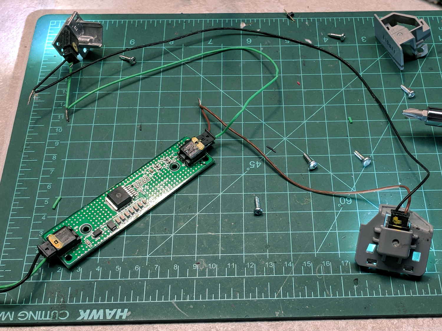
Fly6 – battery replacement – PCB
The PCB goes under a manila paper layer, the ends get similar caps, and the whole affair receives an obligatory Kapton tape wrap:
Fly6 – battery replacement – endcap
Reassembly is in reverse order. I now know the Fly6 will reset / start up when the battery connector snaps into place, but, because it emits identical battery-charge beeps when it starts and shuts off, there’s no way to tell what state it’s in. I don’t see any good way to install the ribbon cable from the LED PCB before plugging in the battery, so just blindly press-and-hold the power button to shut it off.
After an overnight charge, it makes videos of my desk just fine and will, I expect, do the same on the bike.
Now that I’ve taken the thing apart, I should open it up and tinker with the (glued-down) camera focus adjustment to discover whether:
It’s slightly nearsighted and, thus, correctable or
Following all the steps recommended by Cycliq Tech Support didn’t improve the situation. It’s just under two years old and thus outside the warranty, so they advised me to buy their new, not-quite-released-yet Fly6, now with Bluetooth / ANT+ / phone app / shiny, but still with a non-replaceable battery.
Seeing as how the Fly6 works as well as it ever did, apart from the minor issue of shutting down both dependably and intermittently, the problem is almost certainly a bad battery. Cycliq does not offer a repair service, nor a battery replacement service; being based in Australia probably contributes to not wanting to get into those businesses. You’re supposed to responsibly recycle the Whole Damn Thing when the battery goes bad. Which, inevitably, it does.
Protip: anything with a non-replaceable battery is a toy, not a tool.
The most recent ride gave some evidence supporting a bad battery. The first shutdown happened after about half an hour and it gave off three battery status beeps (four = full charge, as at the start of the ride) when I restarted it a few minutes later. It shut down again a few minutes later while we were stopped at a traffic signal and gave off one lonely charge beep when I reached back to restart it, indicating a very low battery voltage. The battery voltage (and the number of startup beeps) increased with longer delays between shutdown and restart, but after the first shutdown it’s never very enthusiastic.
Having nothing to lose, let’s see what’s inside:
Cycliq Fly6 Teardown from inside
Don’t do as I did: you should extract the MicroSD card before you dismantle the camera.
Remove the rubber plugs sealing the four case screws:
Fly6 – Exterior screw plugs out
The case pops open, with a ribbon cable between the LEDs and the main circuit board:
Fly6 – Case opened
Pull the ribbon cable latch away from the connector before pulling the cable out.
It’s amazing what you find inside a blinky taillight these days:
Fly6 – PCB Top side
I’m sure there’s a fancy 32 bit RISC computer in the big chip, along with plenty of flash ROM just below it. The clutter over on the right seems to be the power supply. Yeah, it has a camera in addition to blinky LED goodness, plus USB charging, so eight bits of microcontroller aren’t nearly enough.
Note: the case screws are slightly longer than the PCB retaining screws:
Fly6 – Case and PCB Screws
The underside of the PCB has even more teeny parts, along with, mirabile dictu, a battery connector and (most likely) battery charging stuff:
Fly6 – PCB Underside
A plastic piece holds the “Rechargeable Li-Ion Battery Pack” in place:
Fly6 – Battery in place
A strip of gooey adhesive holding the mic and speaker wires in place also glues the battery strap to the case, but it will yield to gentle suasion from a razor knife.
Pause to count ’em up:
Four case screws (longer)
Three PCB screws
Two battery screws
It looked a lot like an ordinary 18650 lithium cell to me and, indeed, it is:
Fly6 – Battery – label
More razor knife work removes the outer shrinkwrap. The cell has a protection PCB under the black cardboard cover:
Fly6 – Battery Protection PCB – on 18650 cell
I don’t know what the yellow wire does:
Fly6 – Battery Protection PCB – wire side
The FS8205A on the left may be an SII S8205 protection IC preset and packaged for a single cell:
Fly6 – Battery Protection PCB – components
After all that, yeah, it’s a dead battery:
Fly6 OEM 18650 – EOL – 2017-12-06
The red curve shows the in-circuit charge state after taking it apart, the green curve comes from charging the bare cell in my NiteCore D4 charger. I have no idea what the nominal current drain might be, but a 0.25 Ah capacity is way under those Tenergy cells.
A new cell-with-tabs should arrive next week, whereupon I’ll solder the protection circuit in place, wrap it up, pop it back in the case, and see how it behaves.
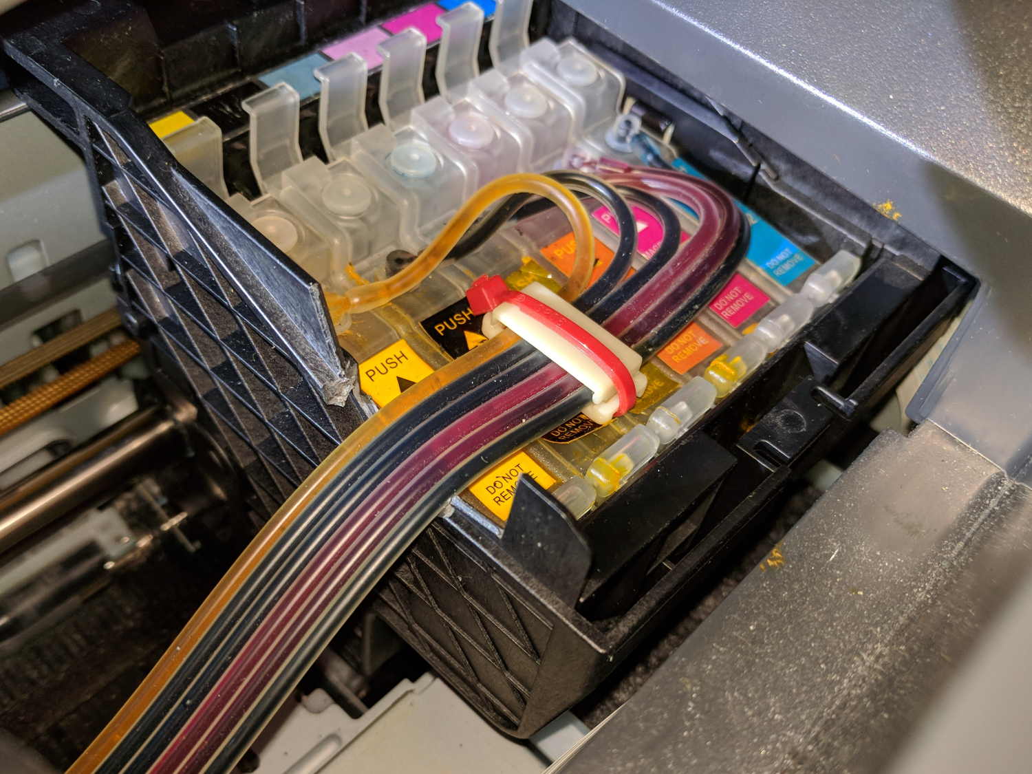
After fixing the yellow ink tube, the Epson R380 printer occasionally gave off a horrible clunk as the tubes slapped around inside the frame. This routing seems much quieter and, as you can see from the marks on the tubes, leaves much less free to flop around:
Epson R380 Printer – CISS tube routing
I cut a small collar (to the left of the white block with the red cable tie) to guide the tubing up over the edge of the ink cartridge holder, with a ramp from the upper edge and raised edges to hold the tubes in place, from a block of black closed-cell foam. It seems perfectly happy to do its job without anything other than the tubes holding it in place atop the cartridges.
There’s also a block of foam filling a gap under the printer’s top frame member (along the far left edge of the picture) to cushion the tubes as they whack against the edge.
So far, so good.
I’ve dumped a few more tanks of waste ink down the drain. When this printer eventually gives up, I’ll get a color laser and move on.
The straight-ish crack between the tube ends looks like it happened as the (yellowed) plastic ruptured and hardened.
Not wanting to get a face full of glass fragments spiced with metallic mercury, I wrapped a blast shield around the spiral tube:
Failed CFL – tube wrap – shattered base
The terminal ends fit loosely in the crumbling base at the start of this operation, leaving the tube wobbling above the base. The plastic cracked as I wrapped the tube, so, for lack of anything smarter, I applied a pin punch to break away the rest of the upper base.
The tube doesn’t fit into a socket, of course, and terminates in four wire connections:
Failed CFL – tube terminals
Those wires pass through notches on the edge of the PCB, bend around the board, pass through vias, and get soldered to pads. The solder side faces the tube, with all the components nestled into the base toward the screw terminals:
Failed CFL – PCB solder side faces upward
The component side sports a surprising number of parts:
Failed CFL – PCB components – 2
A view from the other direction, where you can see the tube wires curling around the edge:
Failed CFL – PCB components – 1
I generally harvest inductors & suchlike, but it got really really hot in there and, methinks, cooked the life out of the parts:
Failed CFL – overheated capacitor
The PCB date code stamp could be “730”, suggesting either 1997 or 2007. In any event, it’s been a while.
I hope LED bulbs outlast these things, but I have my doubts …
Plugging an Arduino with GRBL into a USB port on a Raspberry Pi 3 with bCNC causes an immediate crash: the Arduino doesn’t power up and the Raspberry Pi stops responding. A hardware reset / power cycle with the Arduino plugged in doesn’t improve the situation, so it seems the Arduino draws more current from the USB port than the default setup will allow.
Most likely, the Arduino’s 47 μF power supply caps draw too much current while charging, as the steady-state current seems to be around 40 mA:
RPi vs Arduino – USB current
The solution / workaround requires a tweak to /boot/config.txt:
#-- boost USB current for Arduino CNC
max_usb_current=1
# blank line above to reveal underscores
Update: As mentioned in the comments, the max_usb_current option doesn’t apply to the Pi 3 you see in the picture and, thus, shouldn’t have changed anything. Your guess is as good as mine.
I’d be more comfortable with a separate power supply plugged into the Arduino’s coaxial power jack, but that’s just me.
Radio communication between our bikes failed on the way back from a grocery ride and the problem turned out to be a failed radio:
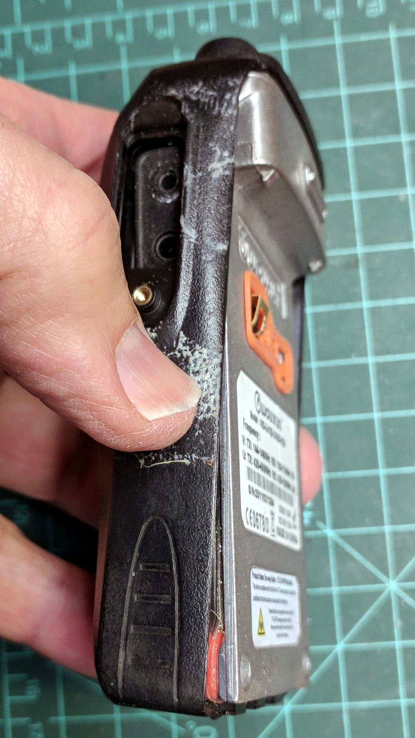
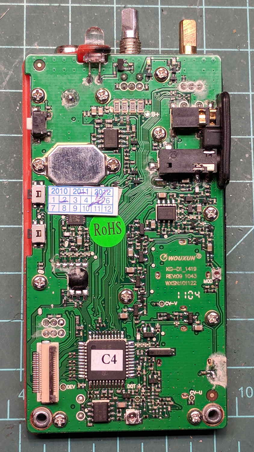
Wouxun KG-UV3D – defunct
The Wouxun KG-UV3D radio seems jammed firmly somewhere in its power-up sequence, doesn’t respond to any buttons, and has no hard-reset switch. On the other paw, it’s been in constant (and rugged!) use for almost exactly five years, so I suppose it doesn’t owe me much of anything.
The new radio, another KG-UV3D from PowerWerx, has marginally different spacing around the screw attaching the plug cover preventing the previous screw from fitting, so I kludged up a screw from a 2 mm socket-head screw, a 2.5 mm (yes) washer, and a pair of 2 mm nuts:
Wouxun KG-UV3D – APRS plug plate screw
Which looks a bit odd, but holds the plug adapter plate firmly in place:
Wouxun KG-UV3D – APRS Voice Plug Block
I suppose when the radio on my bike fails, I must rebuild both APRS + voice interfaces for Yet Another Radio, because the Wouxuns will be completely unobtainable.
The weather abruptly became too cold for riding, at least for sissies such as we, but maybe we’ll get out later in the month …