After hairballing an LM75A I²C temperature sensor to verify at least one of the eBay lot worked, a bag of SOIC-to-DIP space transformers arrived, so I soldered up another LM75A:

The SOIC chip pattern sits at right angles to the DIP pins, which took some getting used to.
The slightly defocused wire connecting pin 4 (on the IC) to pins 5, 6, and 7 (on the PCB) selects address 0x48.
So I flipped it over, soldered four wires (+5 V, GND, SDA, SCL) to the numbered pins on bottom of the board, made up a little header for the other end, wired a socket strip on the crystal tester board, plugged it in, and … nothing worked.
Turns out that the other side of the board carries a TSSOP pattern, which I’d neatly masked off with a snippet of Kapton tape, surrounded by eight numbered pins. Of course, those pin numbers correspond to the TSSOP pattern facing you, so they’re mirror-imaged for the SOIC pattern on the other side.
Soooo, the proper wiring for the SOIC pattern as seen from the TSSOP side has the pin numbers exactly bass-ackwards:
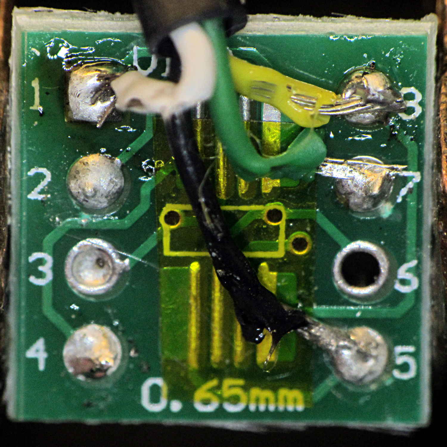
The insulation looked a lot better the first time I soldered the wires to the PCB. Honest.
Anyhow, when correctly wired, the LM75A worked as it should:
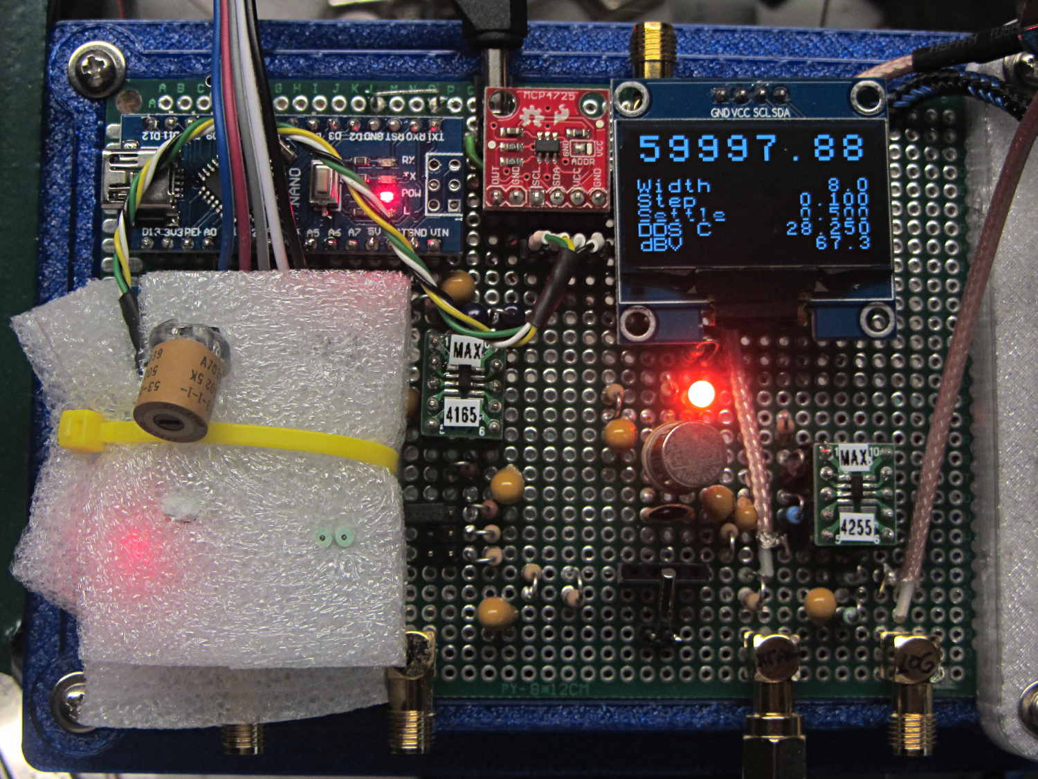
It’s snuggled chip-down against the top of the 125 MHz oscillator can, with a dab of heatsink compound improving their thermal bond and a yellow cable tie around the foam holding them together. The socket header is wired pin-for-pin to the DAC I²C socket directly above it.
The OLED temperature display shows 28.250 °C, because the oscillator just started up in a cool basement. It’ll eventually settle around 39-ish °C, where its output should be pretty close to the 125 MHz – 344 Hz value hardcoded into the source.
Oh, that’s a 3 mm amber LED next to the relay can: much less glaring than the white LED, no matter what it looks like here.

Comments
3 responses to “LM75A vs. SOIC Adapter: Mirror Imaging”
Don’t take this the wrong way (everybody’s a critic, right?), but those solder joints look awful :) Is it lead free solder?
On the subject of getting it wrong, last week I’ve spent 4 hours mangling a 20 pin 2mm pitch flat flex surface mount connector lifted from a (now definitely) defunct HP inkjet to a 100mil island raster PCB just to find out that I rotated it 180 degrees – all this after I’ve managed to wire all the pins of course (facepalm). Hot air gun managed just scorching the PCB substrate (no FR4 in sight) so I ended up cutting up the connector, removing pins one by one, salvaging a new one from yet another HP and resoldering it after TWICE rechecking the orientation.
In the end I’ve spent two 4 hour sessions on a job that would lasted 30 minutes if I just got the proper PCBs made.
On semi related subject, these guys (https://easyeda.com/order) apparently do 10pcs, 10x10cm boards for 2$ plus shipping – haven’t tried them yet but that will change soon :)
That’s genuine 60-40 leaded solder, applied according to my The Bigger The Blob, The Better The Job principle: I was so annoyed.
[…] the joystick button and LM75 temperature sensor running, this chunk of code lets you nudge the nominal DDS oscillator frequency by 1 Hz every 100 […]