Ed Nisley's Blog: Shop notes, electronics, firmware, machinery, 3D printing, laser cuttery, and curiosities. Contents: 100% human thinking, 0% AI slop.
The ESR02 reports one as a 4.8 µF capacitor, the other as a “defective part” with a 4 kΩ resistance. Having a cap fail by turning into a resistor is surprising; I’m more surprised it didn’t simply burn up.
After not quite seven years, the acrylic caulk holding our garden dragonfly’s eyeballs in place lost its grip. Some cleaning of marbles and scuffing of copper sockets later, two rings of JB Kwik should do the trick:
The Sherline CNC mill setup for sawing around the midline:
Sony NP-FM50 battery – Sherline saw setup
Adjust the saw to cut along the seam, set X=0 at the surface, jog to about X+0.7 mm, jog the saw along the seam, then repeat for the other three sides. No real CNC involved, but it’s much easier than sawing or breaking through the seam by hand.
These two packs came with the camera:
Sony NP-FM50 battery – 2003-era cells
The cells have only lot numbers, no manufacturer ID. Wikipedia sayeth Sony Fukushima started in 2000; perhaps these were early production units with no branding.
The center strap running the length of the pack didn’t seem long enough, because I mistakenly thought I’d straightened its end while unsoldering it. As it happens, the end was straight and secured to the PCB by structural solder:
Sony NP-FM50 battery – PCB center tab joint
Moral of the story: pay attention, dammit!
The other end of the center strap required a snippet of tin strip to reach the tabs:
Sony NP-FM50 battery – rebuilt center strap
Aligning the cells that way allowed me to just bend the other tabs over the PCB pads and solder them in place:
Sony NP-FM50 battery – rebuilt PCB contacts
Then a strip of Kapton tape across the kerf holds the case together well enough to survive our gentle usage:
Sony NP-FM50 battery – Kapton belly band
The battery packs require a brief stay in the charger to reset the PCB’s lockout circuitry, after which they work fine:
Sony NP-FM50 – 2019-04-12
The two oldest batteries (OEM 2003 A and OEM 2003 B) have new identities to suit their new innards: 2019 E and 2019 F. The DOA eBay battery retains its 2019 D label after the rebuild, as there’s little room for confusion.
Admittedly, it’d be easier / cheaper / faster to buy third-party NP-FM50 packs directly from eBay or Amazon, but this way I know the cells aren’t complete crap and I get some Quality Shop Time™ out of the deal.
One of my Wyze V2 cameras either arrived with dead IR hardware or failed early on in its tenure here, but it simply didn’t work in night-vision mode: the IR LEDs didn’t turn on and the IR-cut filter didn’t move. Neither the Official Wyze App nor the Xiaomi-Dafang Hacks firmware had any effect, so I expected a (possibly simple) hardware problem.
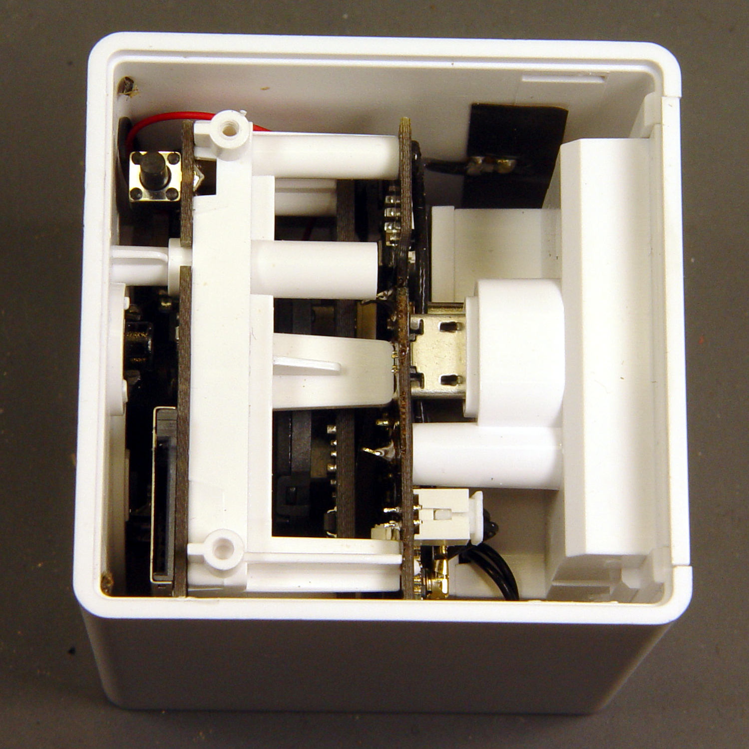
The first hint of trouble was finding the case had only one of the two screws securing its bottom lid, with the missing screw having never been installed. Removing the single screw and prying a bit popped the lid, revealing the innards:
Wyze V2 – interior bottom view
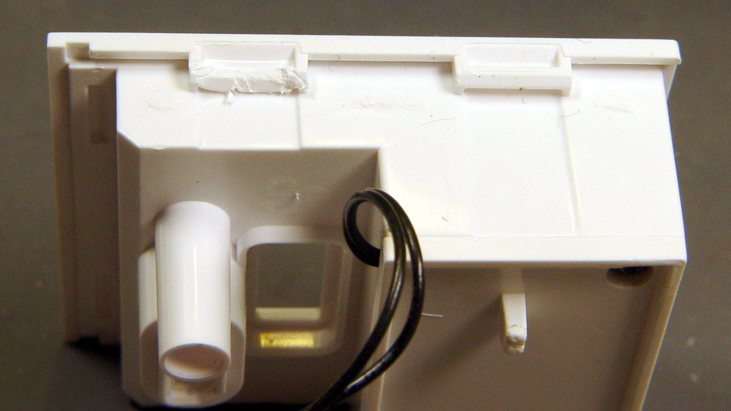
The rear panel (on the right) comes off after abusing the snaps holding it to the main case:
Wyze V2 – rear panel snaps
That’s best done with a small, designated Prydriver, rather than a screwdriver to which you have a deep emotional attachment.
The corresponding part of the main body shows less abuse:
Wyze V2 – case snaps – WiFi antenna
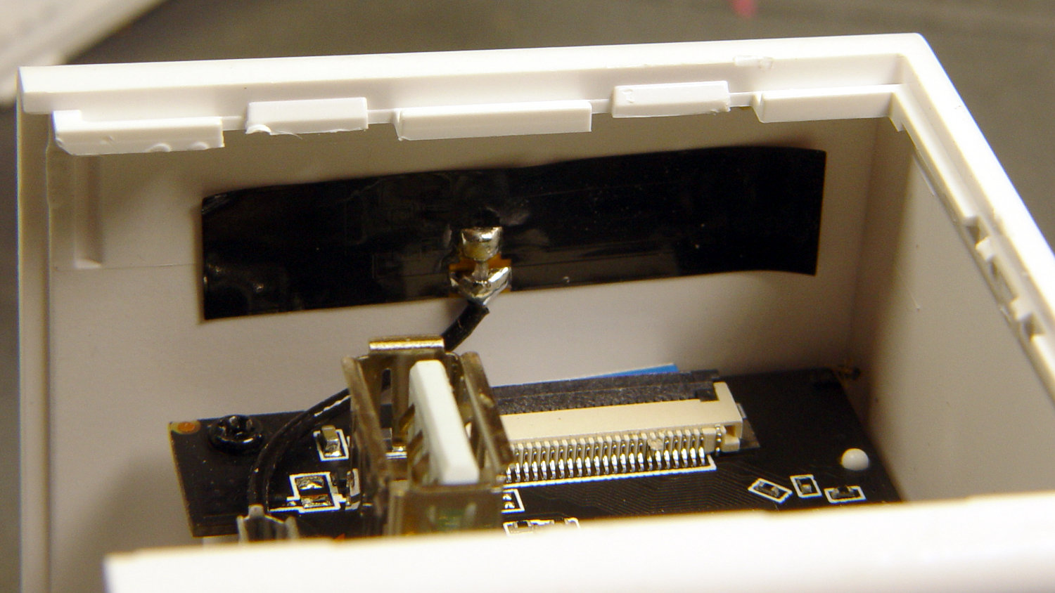
The black patch is the WiFi antenna, which you must unplug from the top board before going much further.
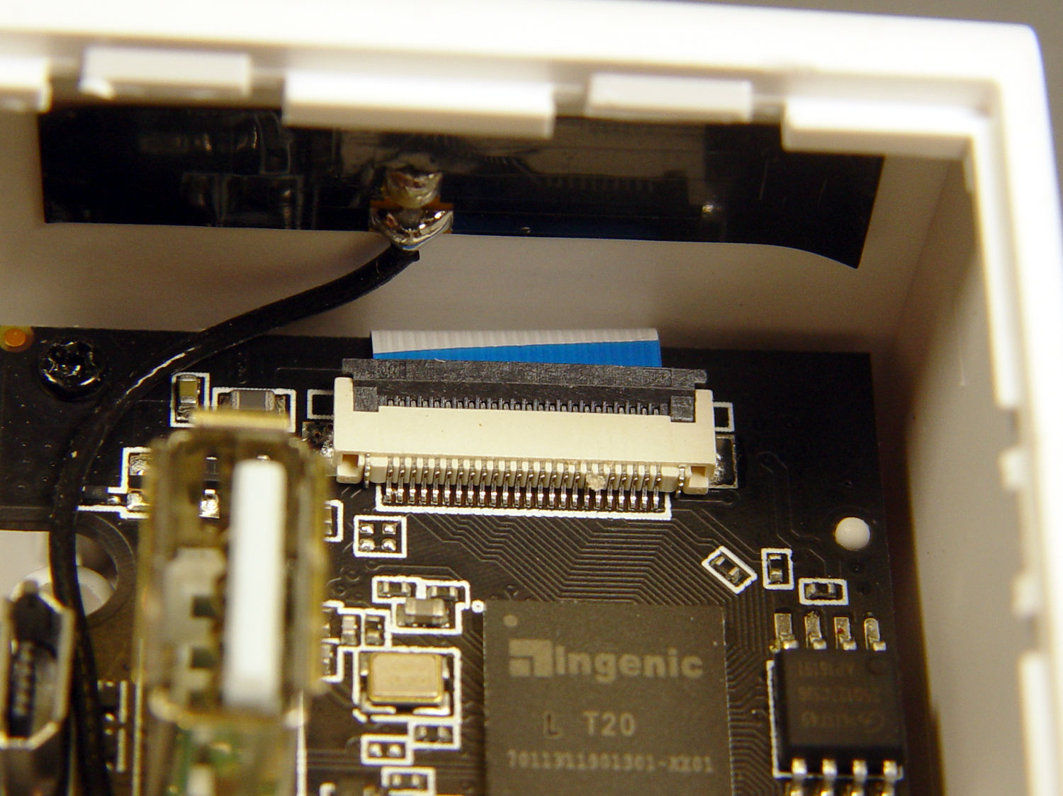
The small blue wedge below the antenna gave me hope I’d found the root of the IR problem:
While I had the case open, I extracted everything and looked it over:
Wyze V2 – front PCB – LED pin soldering
The IR LED soldering left a bit to be desired, so I touched up those joints and washed off most of the flux.
Alas, the IR hardware still didn’t work with everything stuffed back in the case. There are worse things than having a small daylight-only IP camera, though.
Having won an eBay action for a known-dead Sony DSC-F717 at $0.99 (plus $15 shipping, the seller being no fool), I now have a possibly salvageable camera, a Genuine Sony AC supply, and two more NP-FM50 batteries for about the price of any one of the components.
One battery arrived stone-cold dead, suggesting the camera had been put away with the battery installed for a very long time and they died companionably. The camera still charges a (good) battery, even though it doesn’t turn on, and perusing the schematics suggests checking the power switch, because it’s always the switch contacts. That’s for another day, though.
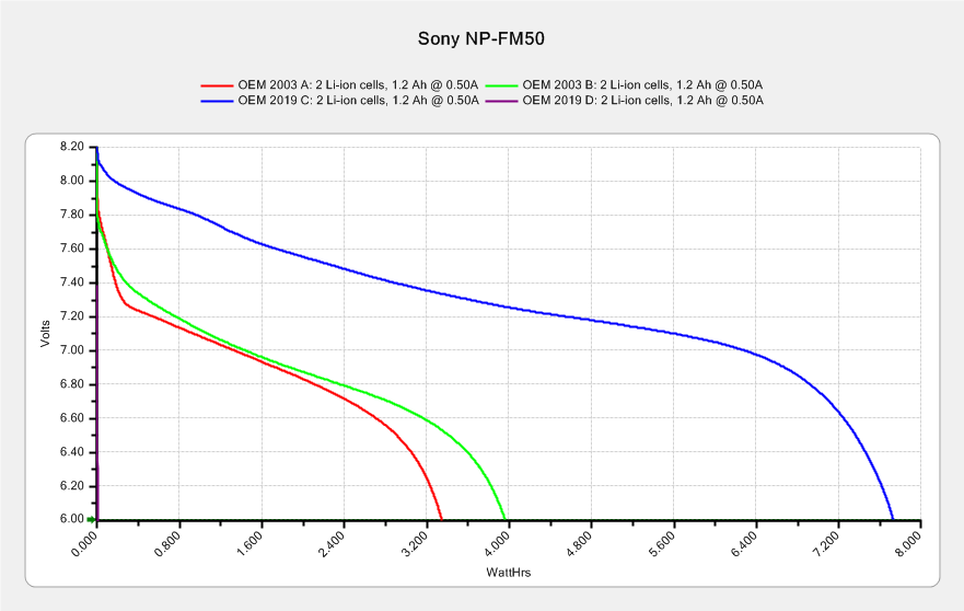
For the record, the battery status:
NP-FM50 – 2019-03-30
The red and green traces come from the two batteries I’ve been cycling through the camera since, um, 2003, so they’re getting on in years and correspondingly low in capacity.
The fourth battery (2019 D, the date showing when it arrived, not its manufacturing date) went from “fully charged” to “dead” in about three seconds with a 500 mA load, producing the nearly invisible purple trace dropping straight down along the Y axis.
The lower cell is lifeless, the upper cell may still have some capacity. Three pairs of 18500 lithium cells are on their way, in the expectation of rebuilding the weakest packs.
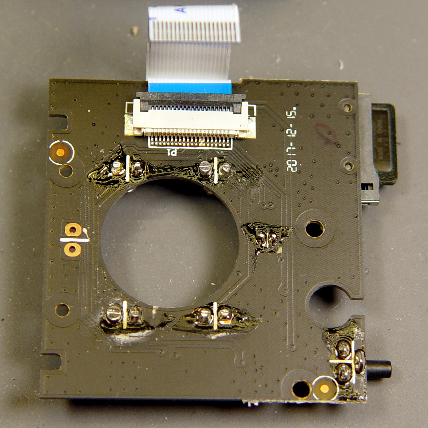
After desoldering the battery tab on the right from the PCB, it occurred to me I needed pictures:
Sony NP-FM50 battery – PCB exposed
Yeah, that’s a nasty melted spot on the case, due to inept solder-wickage.
Unsoldering the three tabs closest to the case releases the cells + PCB from confinement:
Sony NP-FM50 battery – PCB overview
I’m still bemused by battery packs with a microcontroller, even though all lithium packs require serious charge controllers. At least this is an Atmel 8-bitter, rather than 32-bit ARM hotness with, yo, WiFi.
The cells have shaped tabs which will require some gimmicking to reproduce:
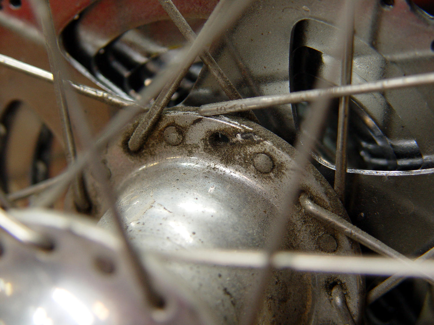
I’d noticed some brake drag on our last few rides, but forgot to check until I saw the rim wobble while extracting images from the rear camera.
It’s a lot easier to fix in the Basement Shop than on the road. After nigh onto a decade since replacing the last broken spoke, perhaps this is a harbinger of doom to come.
Memo to Self: spoke tension is now 20-ish on the drive side, 15-ish on the left.
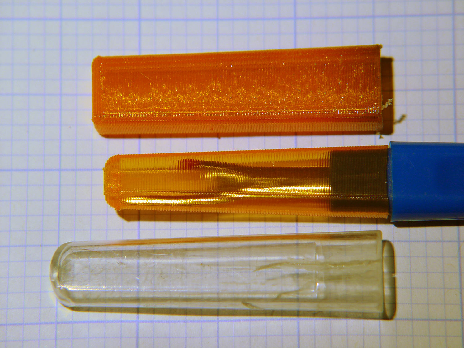
The cover for Mary’s favorite seam ripper cracked long ago, has been repaired several times, and now needs a replacement:
Seam Ripper cover – overview
The first pass (at the top) matched the interior and exterior shapes, but was entirely too rigid. Unlike the Clover seam ripper, the handle has too much taper for a thick-walled piece of plastic.
The flexy thinwall cover on the ripper comes from a model of the interior shape:
Seam Ripper Cover – handle model
It’s not conspicuously tapered, but OpenSCAD’s perspective view makes the taper hard to see. The wedge on top helps the slicer bridge the opening; it’s not perfect, just close enough to work.
A similar model of the outer surface is one thread width wider on all sides, so subtracting the handle model from the interior produces a single-thread shell with a wedge-shaped interior invisible in this Slic3r preview:
Seam Ripper Cover – exterior – Slic3r preview
The brim around the bottom improves platform griptivity. The rounded top (because pretty) precludes building it upside-down, but if you could tolerate a square-ish top, that’s the way to go.
Both models consist of hulls around eight strategically placed spheres, with the wedge on the top of the handle due to the intersection of the hull and a suitable cube. This view shows the situation without the hull:
Seam Ripper Cover – handle model – cube intersection
The spheres overlap, with the top set barely distinguishable, to produce the proper taper. I measured the handle and cover’s wall thicknesses, then guesstimated the cover’s interior dimensions from its outer size.
The handle’s spheres have a radius matching its curvature. The cover’s spheres have a radius exactly one thread width larger, so the difference produces the one-thread-wide shell.
Came out pretty nicely, if I do say so myself: the cover seats fully with an easy push-on fit and stays firmly in place. Best of all, should it get lost (despite the retina-burn orange PETG plastic), I can make another with nearly zero effort.
The Basement Laboratory remains winter-cool, so I taped a paper shield over the platform as insulation from the fan cooling the PETG:
Seam Ripper Cover – platform insulation
The shield goes on after the nozzle finishes the first layer. The masking tape adhesive turned into loathesome goo and required acetone to get it off the platform; fortunately, the borosilicate glass didn’t mind.
This file contains hidden or bidirectional Unicode text that may be interpreted or compiled differently than what appears below. To review, open the file in an editor that reveals hidden Unicode characters.
Learn more about bidirectional Unicode characters