|
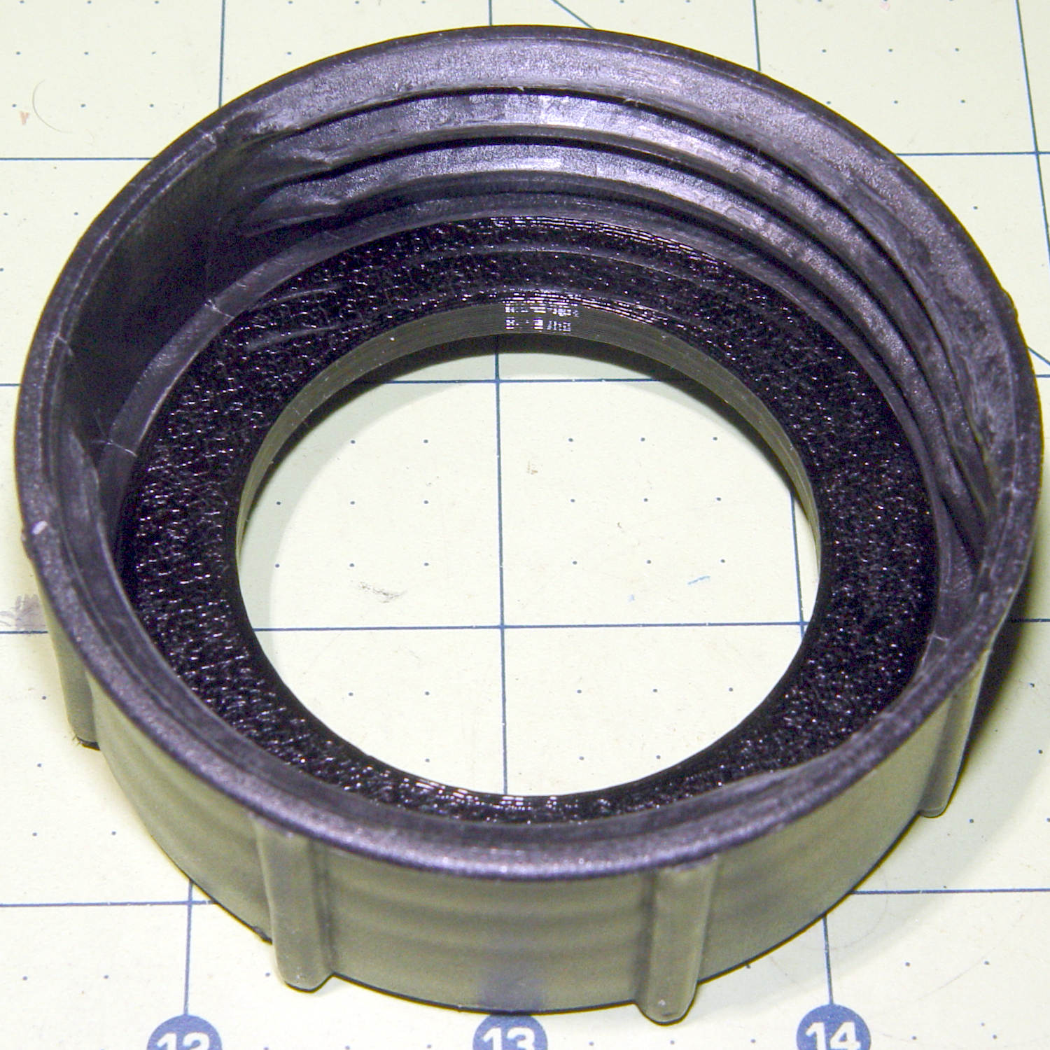
// Rubber Soaker Hose End Connector Clamp |
|
// Helps hold silicone rubber in connector |
|
// Ed Nisley KE4ZNU June 2019 |
|
|
|
Layout = "Build"; // [Hose,Connector,Block,Show,Build] |
|
|
|
//- Extrusion parameters must match reality! |
|
|
|
/* [Hidden] */ |
|
|
|
ThreadThick = 0.25; |
|
ThreadWidth = 0.40; |
|
|
|
HoleWindage = 0.2; |
|
|
|
Protrusion = 0.1; // make holes end cleanly |
|
|
|
inch = 25.4; |
|
|
|
function IntegerMultiple(Size,Unit) = Unit * ceil(Size / Unit); |
|
|
|
//———- |
|
// Dimensions |
|
// Hose lies along X axis |
|
|
|
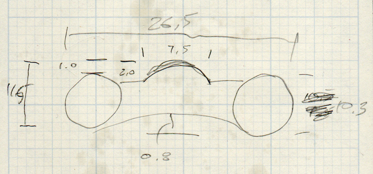
Hose = [200,26.5,11.6]; // X=very long, Y=width, Z=overall height |
|
|
|
RimThick = 10.3; // outer sections |
|
RimOD = RimThick; |
|
RimFlatRecess = 1.0; // recess to front flat surface |
|
|
|
OuterOC = Hose.y – RimOD; // outer tube centers |
|
|
|
RecessM = 0.8; // back recess chord |
|
RecessC = OuterOC; |
|
RecessR = (pow(RecessM,2) + pow(RecessC,2)/4) / (2*RecessM); |
|
|
|
RidgeM = 1.6; // front ridge chord |
|
RidgeC = 7.5; |
|
RidgeR = (pow(RidgeM,2) + pow(RidgeC,2)/4) / (2*RidgeM); |
|
|
|
HoseSides = 12*4; |
|
|
|
Connector = [5.0,33.0,13.0]; // oval brass: X=snout Y=width Z=dia |
|
|
|
Block = [20.0,50.0,4.0 + Hose.z]; // overall splice block size |
|
echo(str("Block: ",Block)); |
|
|
|
Kerf = 0.5; // cut through middle to apply compression |
|
|
|
ID = 0; |
|
OD = 1; |
|
LENGTH = 2; |
|
|
|
// 8-32 stainless screws |
|
Screw = [4.1,8.0,3.0]; // OD = head LENGTH = head thickness |
|
Washer = [4.4,9.5,1.0]; |
|
Nut = [4.1,9.7,6.0]; |
|
|
|
CornerRadius = Washer[OD]/2; |
|
|
|
ScrewOC = Block.y – 2*CornerRadius; |
|
|
|
echo(str("Screw OC: x=",ScrewOC.x," y=",ScrewOC.y)); |
|
|
|
//———————- |
|
// Useful routines |
|
|
|
module PolyCyl(Dia,Height,ForceSides=0) { // based on nophead's polyholes |
|
Sides = (ForceSides != 0) ? ForceSides : (ceil(Dia) + 2); |
|
FixDia = Dia / cos(180/Sides); |
|
cylinder(d=(FixDia + HoleWindage),h=Height,$fn=Sides); |
|
} |
|
|
|
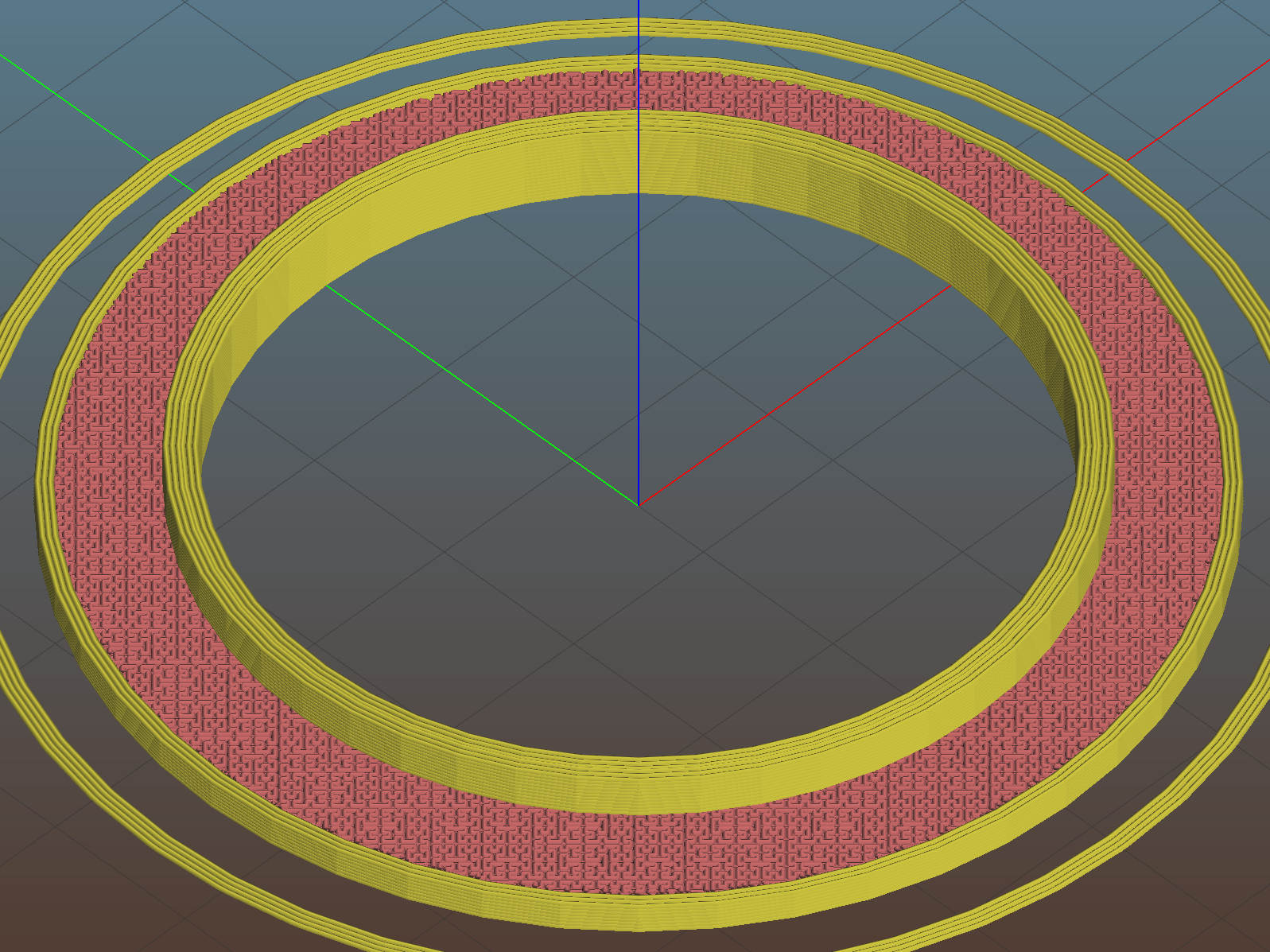
// Hose shape |
|
// This includes magic numbers measured from reality |
|
|
|
module HoseProfile() { |
|
|
|
rotate([0,-90,0]) |
|
translate([0,0,-Hose.x/2]) |
|
linear_extrude(height=Hose.x,convexity=4) |
|
difference() { |
|
union() { |
|
for (j=[-1,1]) // outer channels |
|
translate([0,j*OuterOC/2]) |
|
circle(d=RimOD,$fn=HoseSides); |
|
translate([-RimOD/4,0]) // rear flat fill |
|
square([RimOD/2,OuterOC],center=true); |
|
translate([(RimOD/4 – RimFlatRecess),0]) // front flat fill |
|
square([RimOD/2,OuterOC],center=true); |
|
intersection() { |
|
translate([Hose.z/2,0]) |
|
square([Hose.z,OuterOC],center=true); |
|
translate([-RidgeR + RimOD/2 – RimFlatRecess + RidgeM,0]) |
|
circle(r=RidgeR,$fn=HoseSides); |
|
} |
|
} |
|
translate([-(RecessR + RimOD/2 – RecessM),0]) |
|
circle(r=RecessR,$fn=2*HoseSides); |
|
} |
|
} |
|
|
|
// Outside shape of splice Block |
|
// Z centered on hose rim circles, not overall thickness through center ridge |
|
|
|
module SpliceBlock() { |
|
difference() { |
|
hull() |
|
for (i=[-1,1], j=[-1,1]) // rounded block |
|
translate([i*(Block.x/2 – CornerRadius),j*(Block.y/2 – CornerRadius),-Block.z/2]) |
|
cylinder(r=CornerRadius,h=Block.z,$fn=4*8); |
|
for (j=[-1,1]) // screw holes |
|
translate([0, |
|
j*ScrewOC/2, |
|
-(Block.z/2 + Protrusion)]) |
|
PolyCyl(Screw[ID],Block.z + 2*Protrusion,6); |
|
cube([2*Block.x,2*Block.y,Kerf],center=true); // slice through center |
|
} |
|
} |
|
|
|
// Splice block less hose |
|
|
|
module ShapedBlock() { |
|
difference() { |
|
SpliceBlock(); |
|
HoseProfile(); |
|
Connector(); |
|
} |
|
} |
|
|
|
// Brass connector end |
|
|
|
module Connector() { |
|
translate([-(Block.x/2 + Protrusion),0,0]) |
|
rotate([0,90,0]) |
|
linear_extrude(height=Connector.x + Protrusion) |
|
hull() |
|
for (i = [-1,1]) |
|
translate([0,i*(Connector.y – Connector.z)/2]) |
|
circle(d=Connector.z); |
|
} |
|
|
|
|
|
//———- |
|
// Build them |
|
|
|
if (Layout == "Hose") |
|
HoseProfile(); |
|
|
|
if (Layout == "Block") |
|
SpliceBlock(); |
|
|
|
if (Layout == "Connector") |
|
Connector(); |
|
|
|
if (Layout == "Show") { |
|
ShapedBlock(); |
|
color("Green",0.25) |
|
HoseProfile(); |
|
} |
|
|
|
if (Layout == "Build") { |
|
SliceOffset = 0; |
|
intersection() { |
|
translate([SliceOffset,0,Block.z/4]) |
|
cube([4*Block.x,4*Block.y,Block.z/2],center=true); |
|
union() { |
|
translate([0,0.6*Block.y,Block.z/2]) |
|
ShapedBlock(); |
|
translate([0,-0.6*Block.y,Block.z/2]) |
|
rotate([0,180,0]) |
|
ShapedBlock(); |
|
} |
|
} |
|
} |