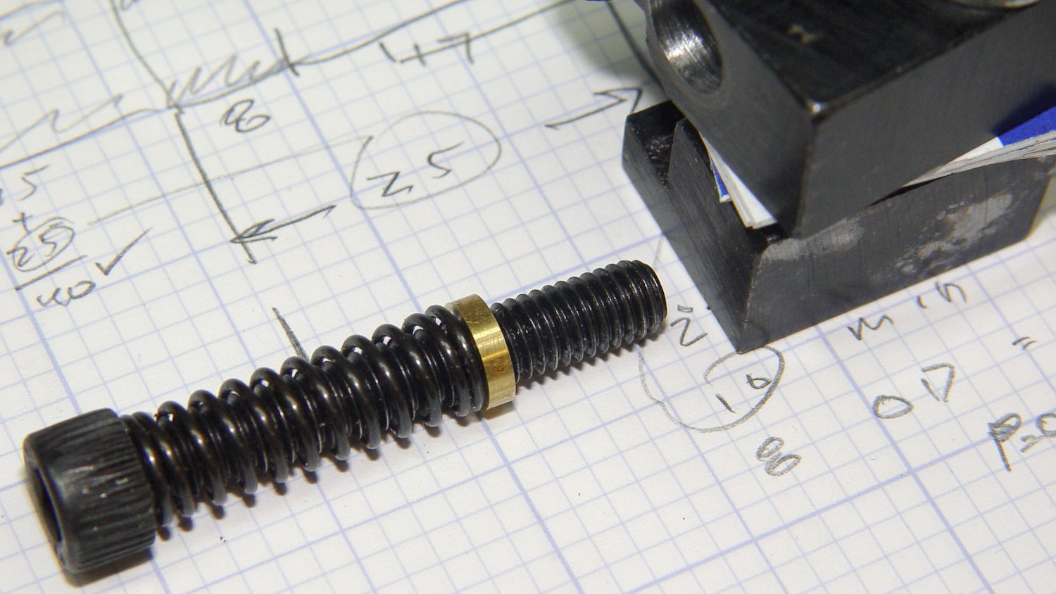
After dismantling the tailstock to apply the tweaks, it was grossly out of alignment, as seen from the top:

Seen from the side, the tailstock center is way too high:
No surprises there.
The object of the game is to make the tailstock bore collinear with the spindle bore in all four degrees of freedom:
- Front-back
- Up-down
- Yaw angle
- Pitch angle
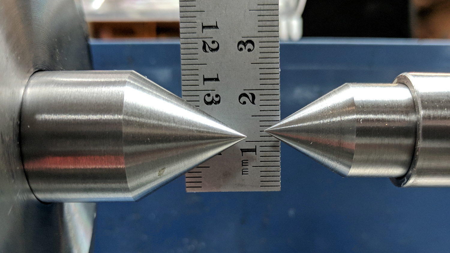
The first step is to match those two points, then measure the angular error.
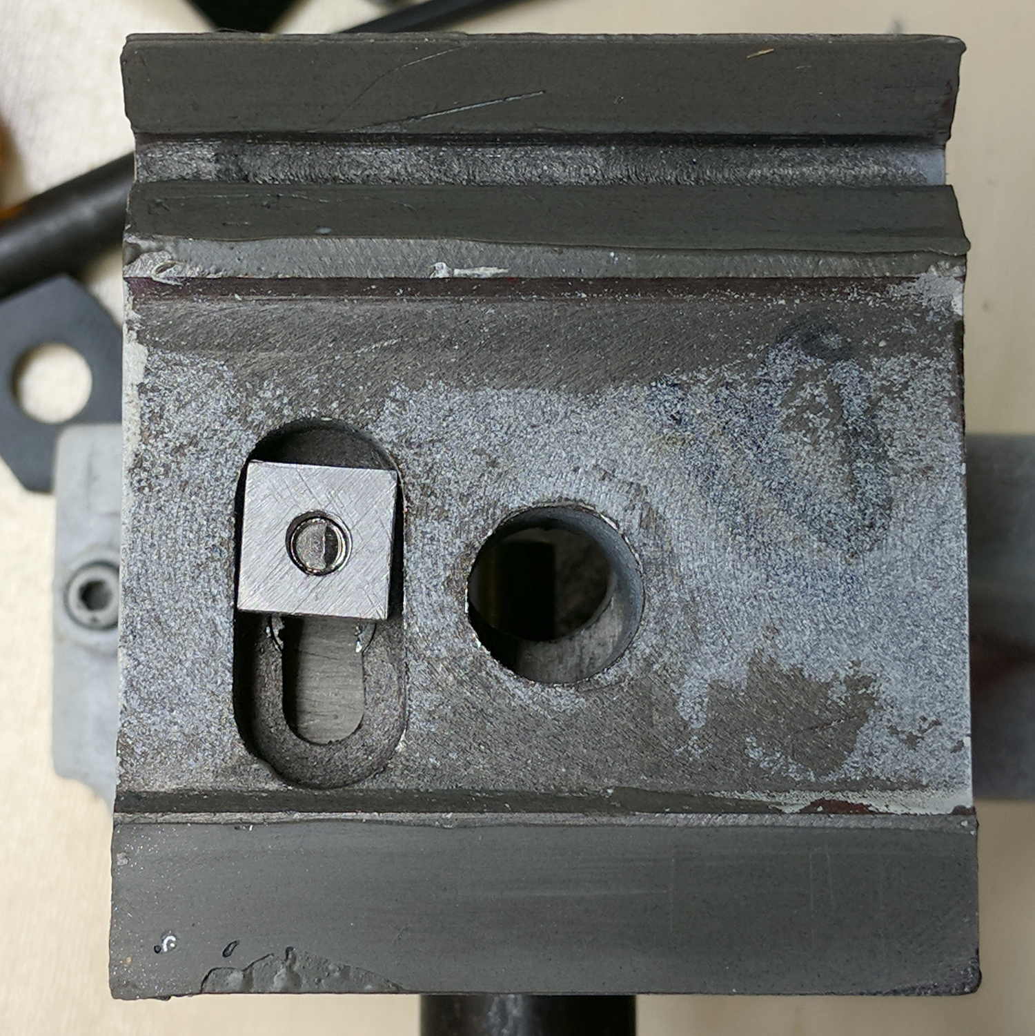
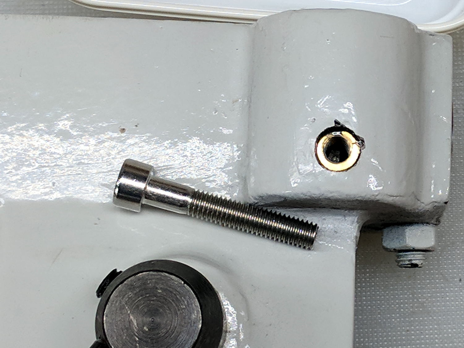
Loosen the (new!) screws holding the tailstock top & bottom castings together:

I set them snug enough to prevent casual motion and loose enough to allow adjustment with gentle taps from a plastic hammer. Tapping the top casting forward lined up the dead centers horizontally, leaving only the vertical alignment.
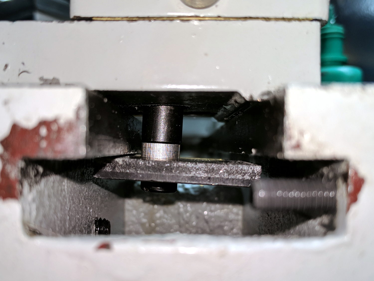
Then I clamped the tailstock’s bottom casting to the lathe bed:
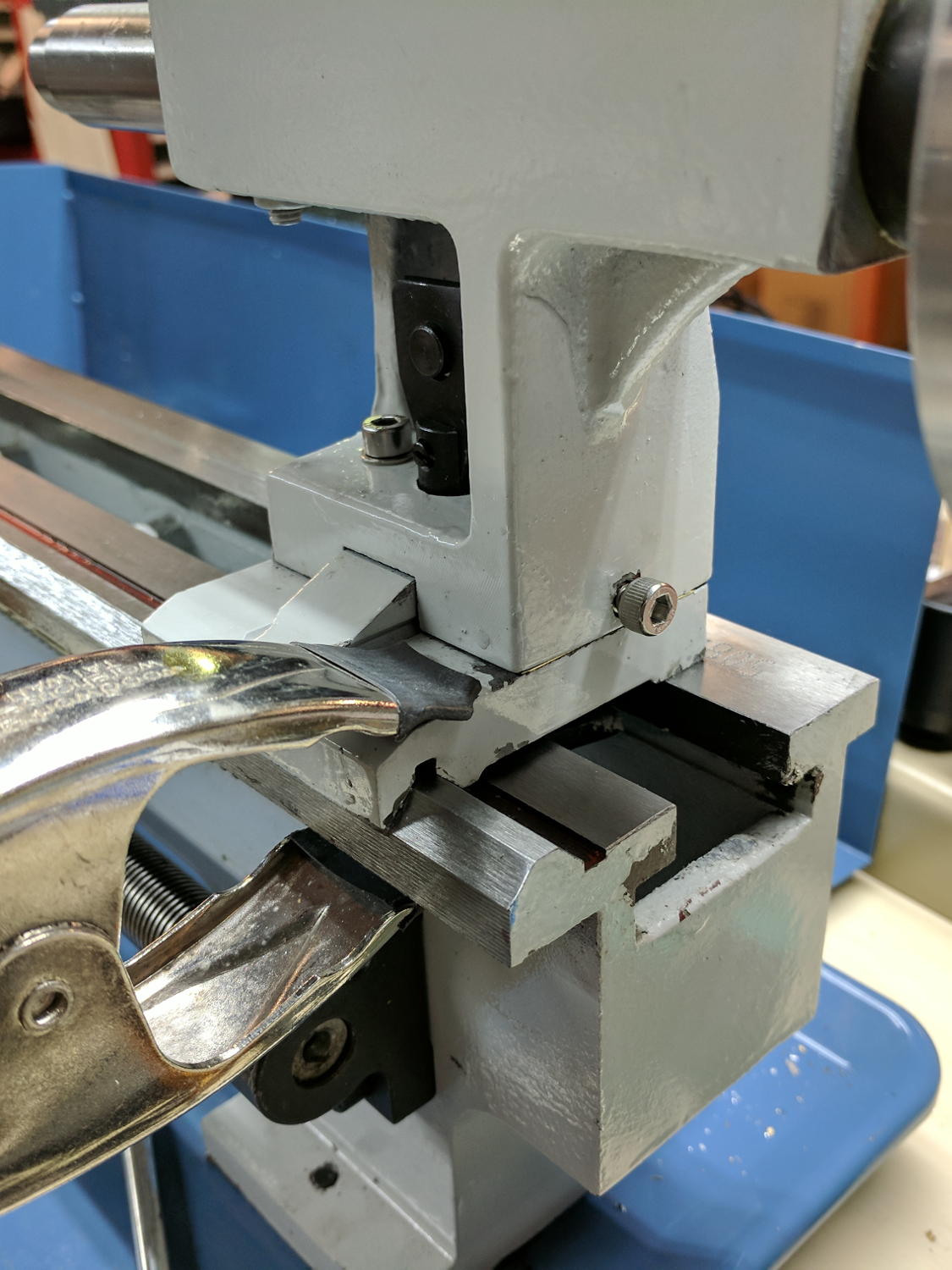
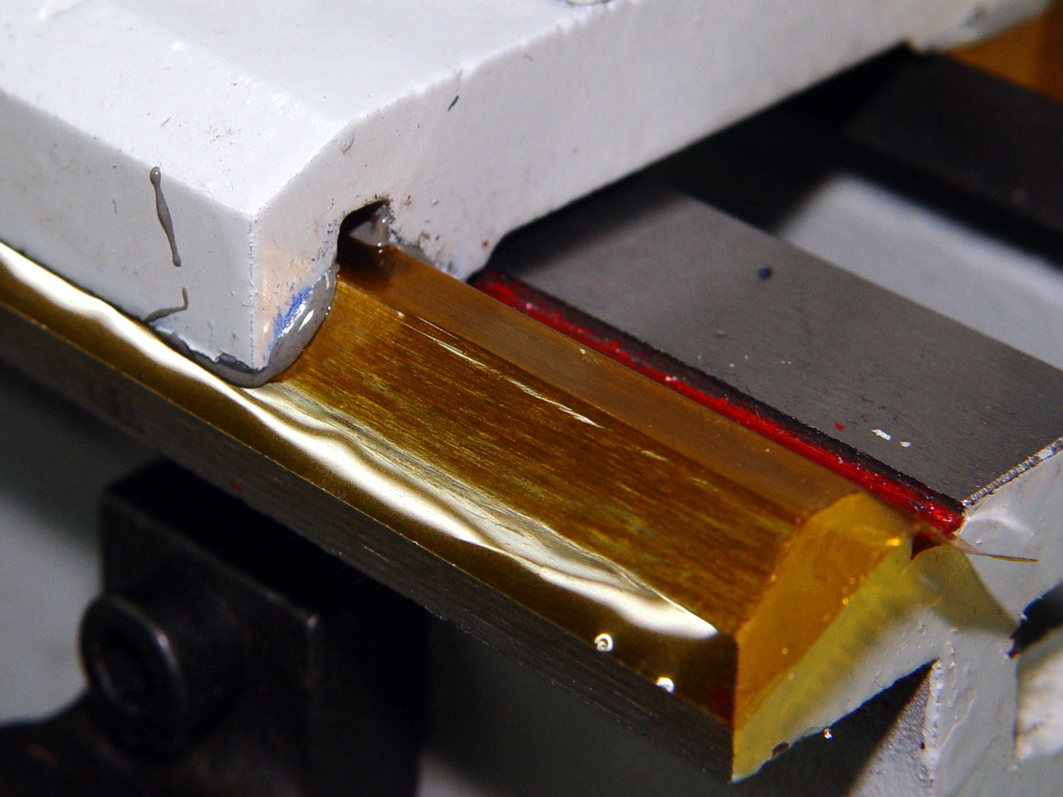
Loosening the screws a bit more let me tilt the top casting to the left and slide a brass shim between the two castings, adding just a little more height to the left side to move the tailstock center downward.
This could do any or all of:
- Correct a pre-existing pitch angle so everything is fine again
- Pitch the tailstock ram axis out of line with respect to the spindle axis
- Confuse the issue
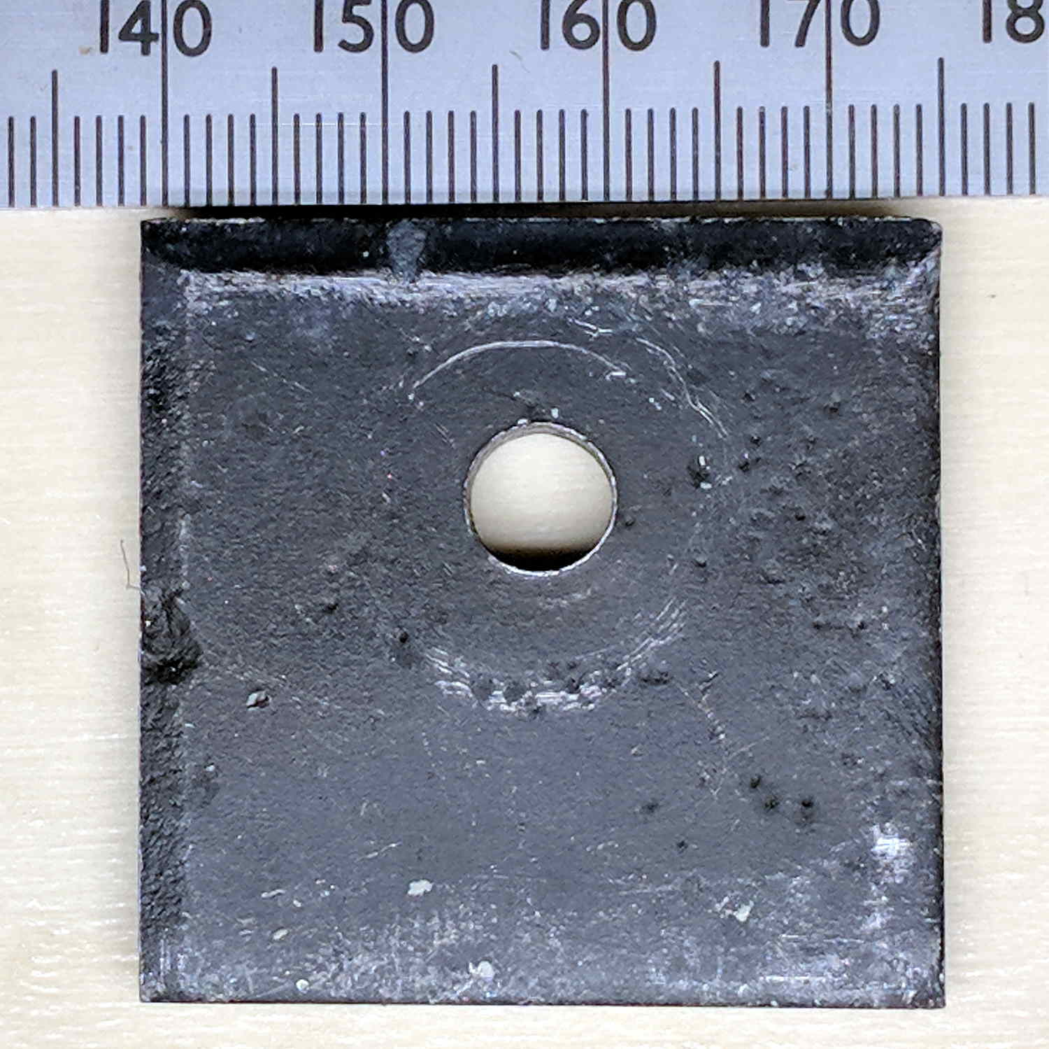
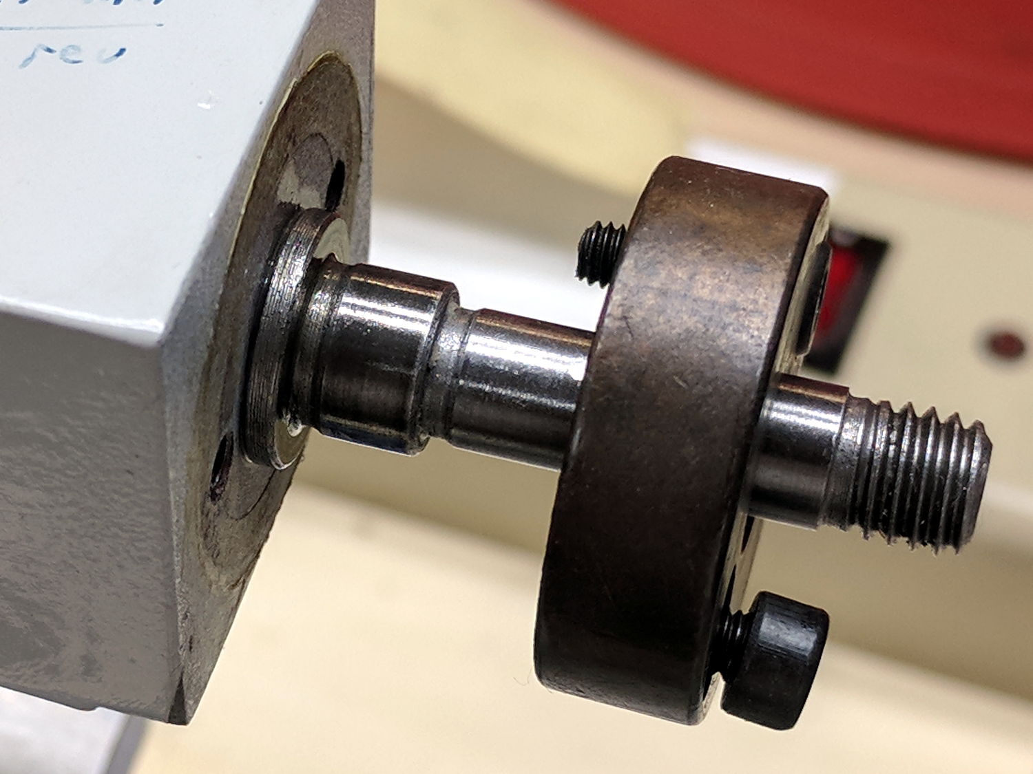
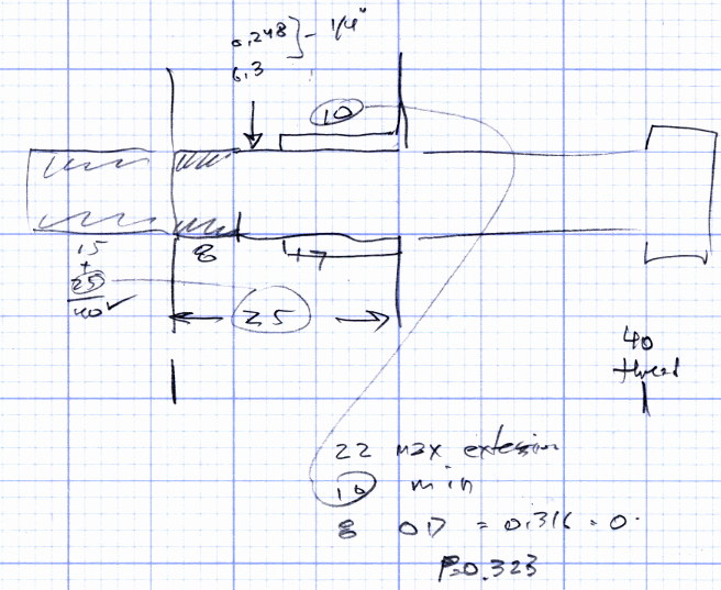
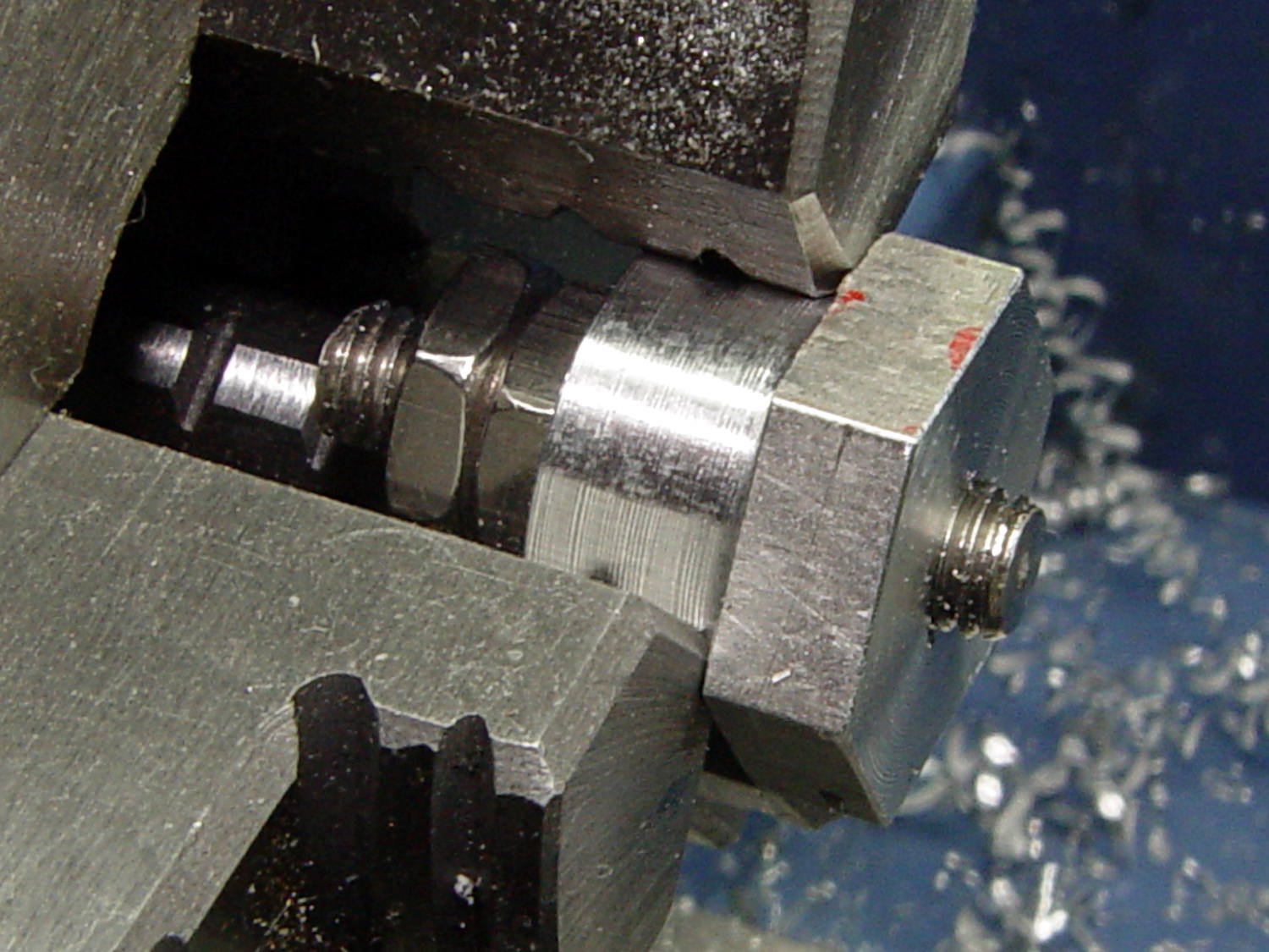
I started with a 6 mil = 0.15 mm shim that didn’t quite do enough and a 16 mil = 0.4 mm shim was a bit too much. Pinching a brass shimstock snippet between the centers show how they match front-back and don’t match up-down, with the tailstock center now too low:
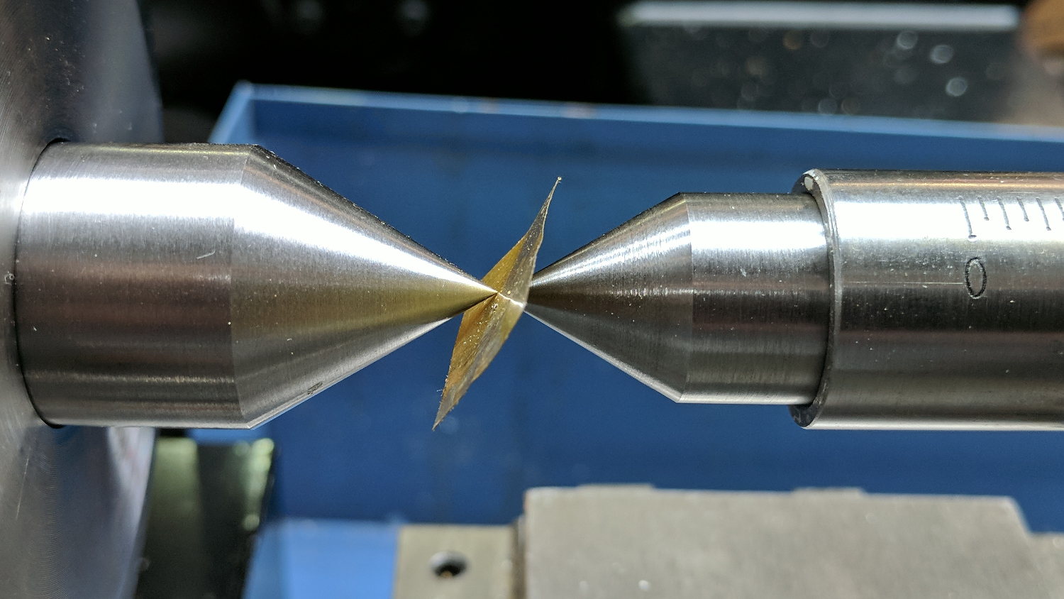
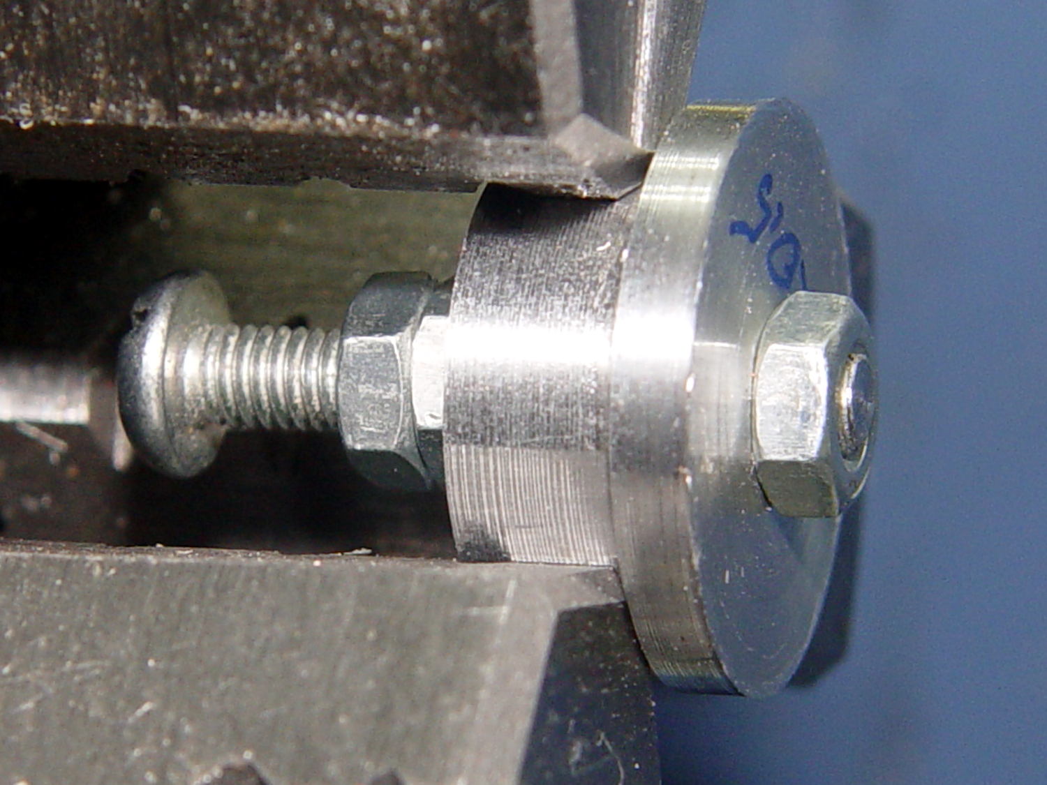
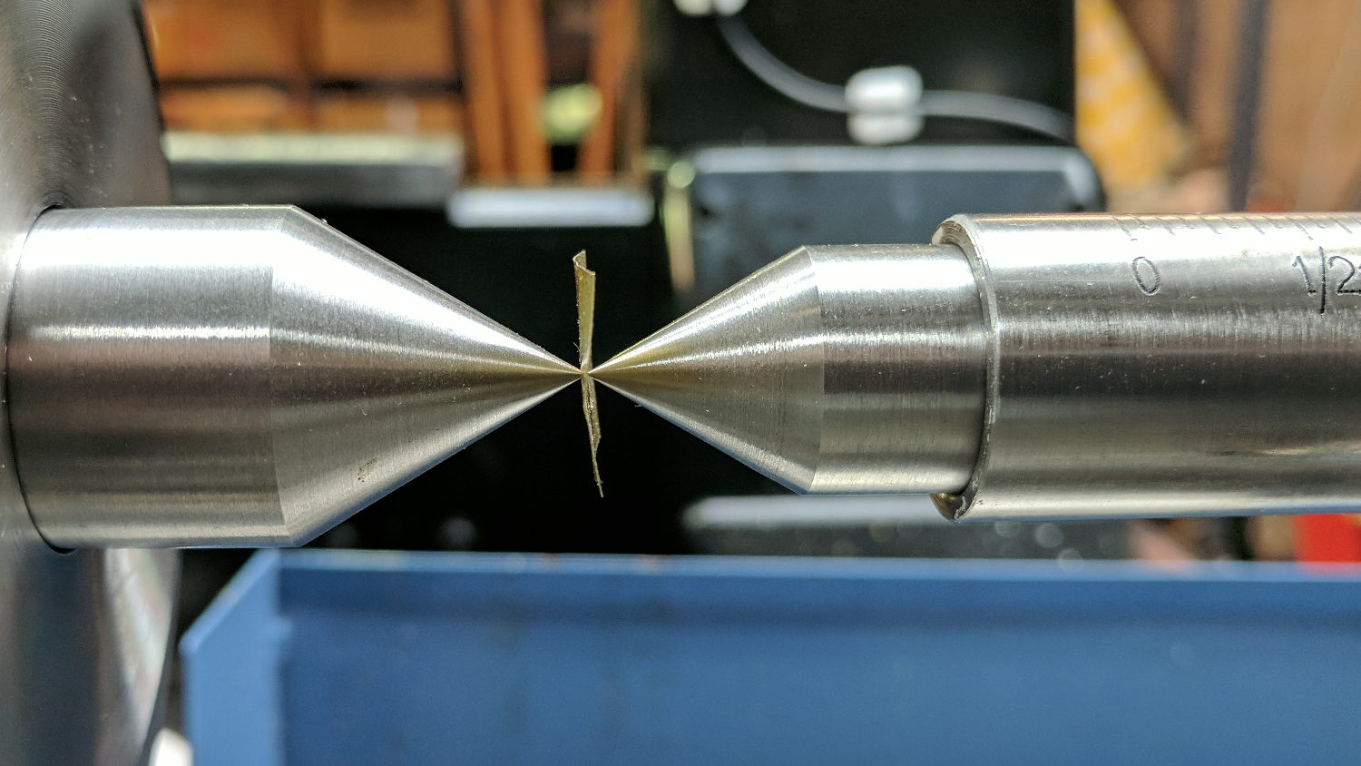
Some back-and-forth fiddling showed a 10 mil = 0.25 mm sheet came out about right:
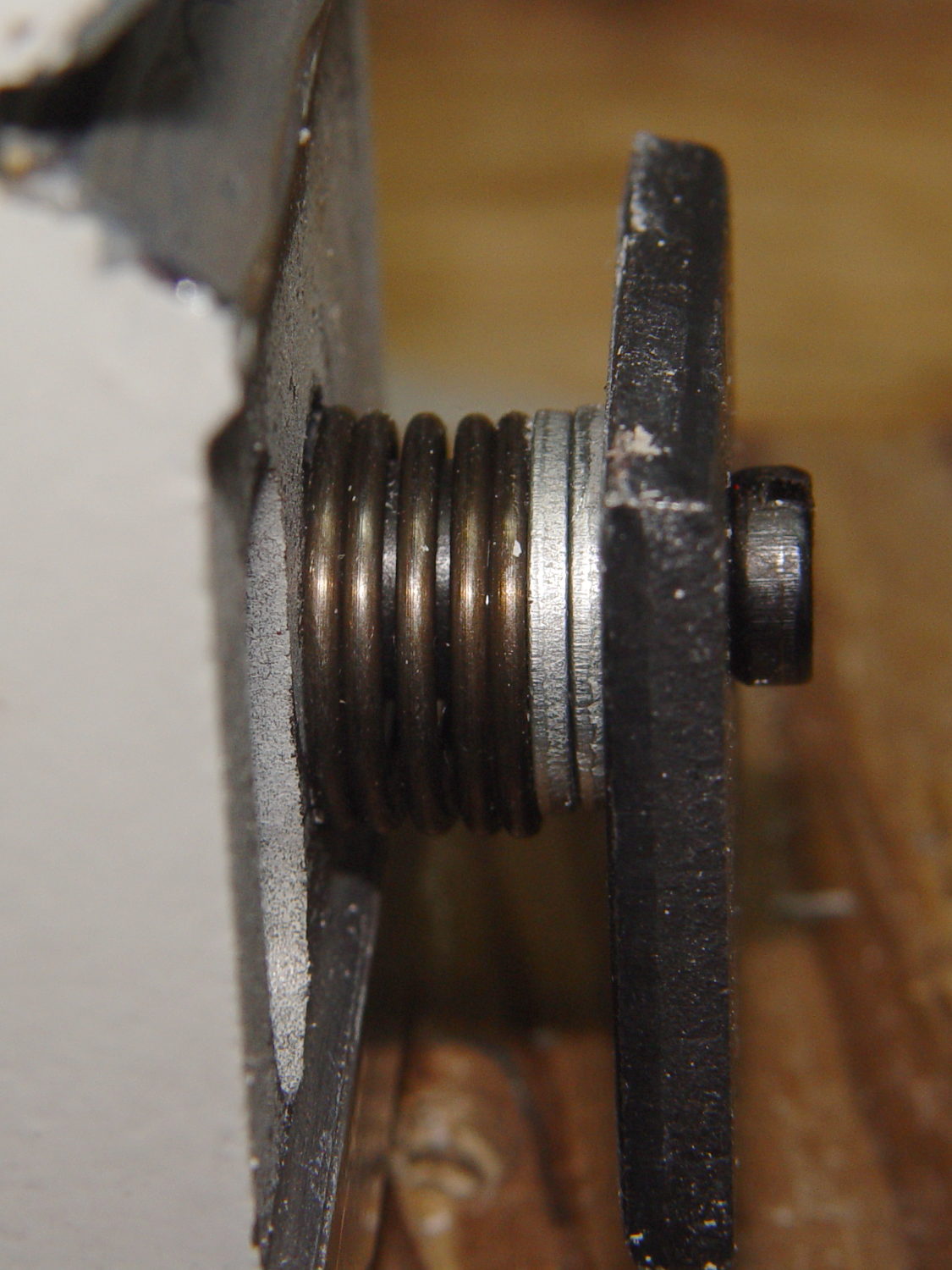
With the two linear degrees of freedom accounted for, measure the yaw angle by comparing the position of the tailstock ram’s far end:

With its near end:

Note: measure the offset by sliding the tailstock along the ways, not by retracting the ram. Reassuringly, the ram slides out parallel to its axis.
Measure the pitch angle, similarly:
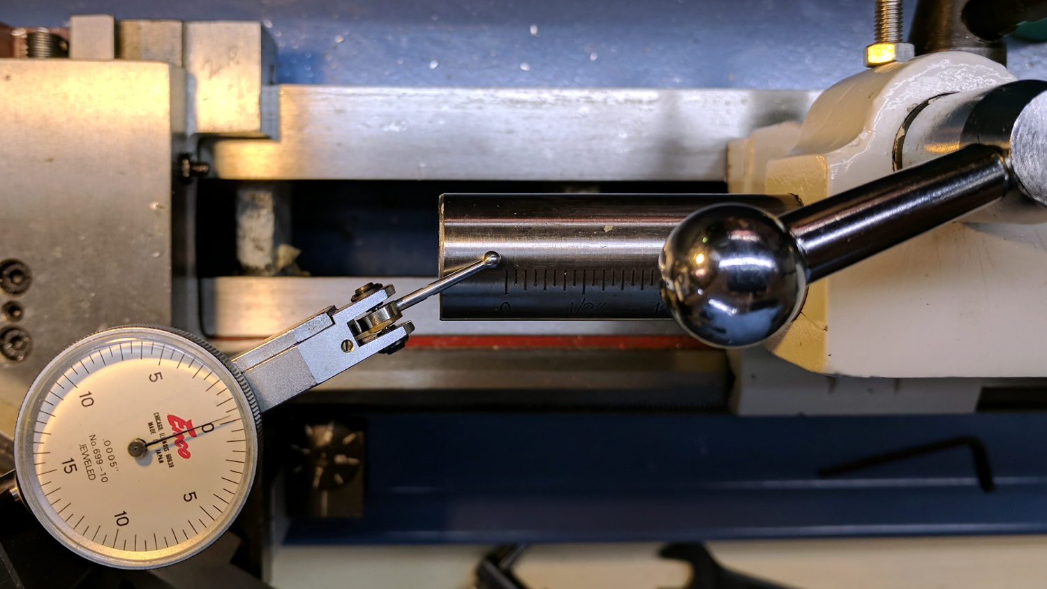
As it turns out, the far end of the ram is 5 mils down and front from its base near the tailstock. Over 1.5 inches of travel, 5 mils works out to 0.19°.
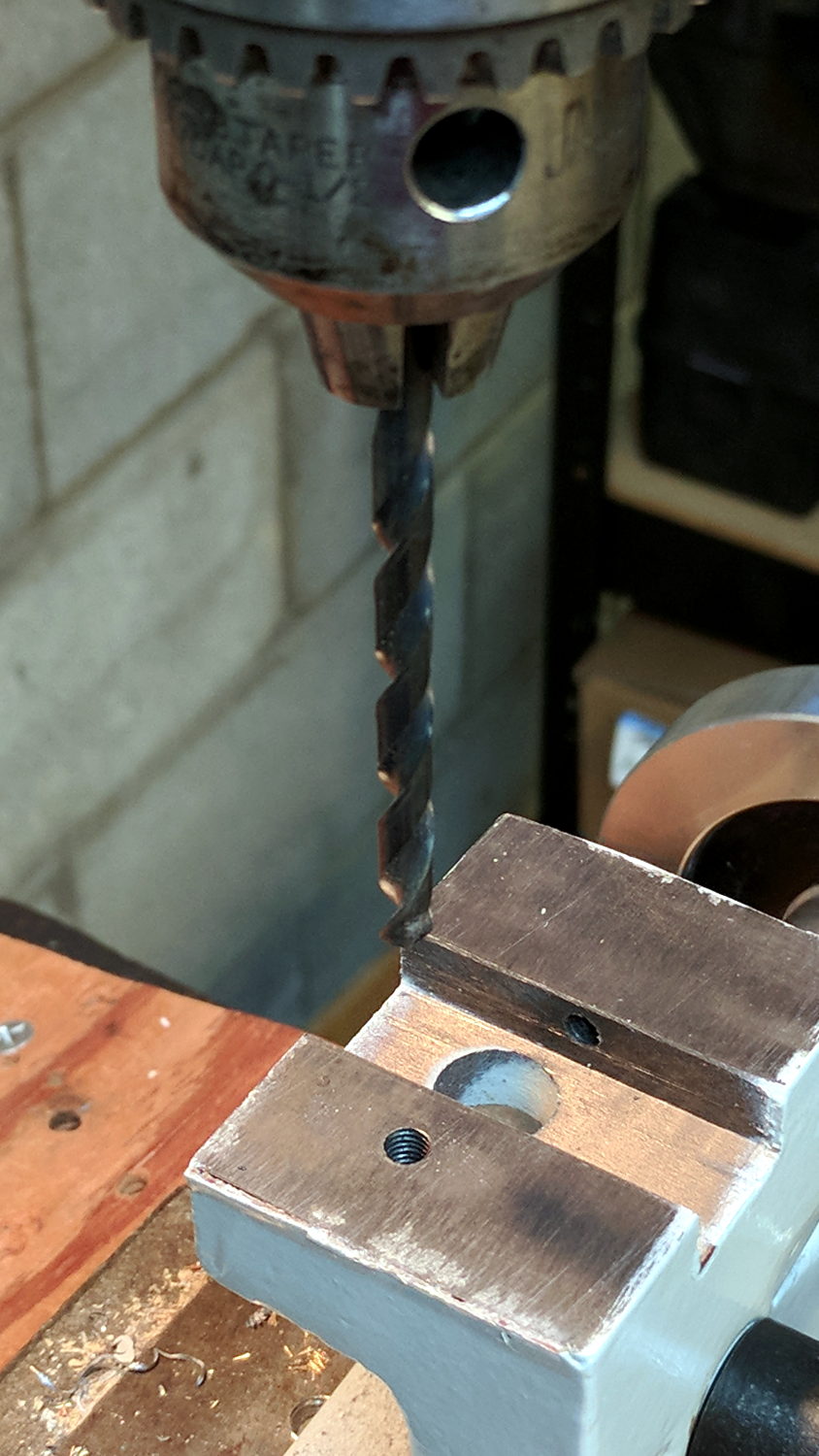
Although it’s a small angle, the huge Jacob chuck supplied with the lathe puts a typical drill 125 mm from where you see the tailstock dead center’s tip. In round numbers, the drill point will be 16 mils low-and-front, about 25 mils radially off-center, which agrees reasonably well with what I actually see:

Because I don’t do much turning between centers, I retinkered the alignment to put a point held in the drill chuck on center. Deep hole drilling won’t work quite right, because the ram extends along those 0.19° angles, but it’s Good Enough for now. It’ll be much easier to correct the yaw misalignment than the height mismatch.
Those of you who read image metadata surely noticed the pix aren’t in ascending temporal order. Verily, this was an iterative process, with pix happening all along the way.