The Smell of Molten Projects in the Morning

Ed Nisley's Blog: Shop notes, electronics, firmware, machinery, 3D printing, laser cuttery, and curiosities. Contents: 100% human thinking, 0% AI slop.

Tag: Mini-lathe

Tweaking an LMS 5200 Mini-Lathe

  • Mini-Lathe Tailstock Way Repair

    After the faceplant caused by the crappy compound way finishing, I decided to try repairing the tailstock ways as a means of gaining experience before tackling the real problem. The general idea is to see whether filling the gouges with epoxy will suffice.

    I’m using good ol’ JB Weld steel-filled epoxy, rather than graphite / molybdenum disulfide loaded epoxy, mostly because:

    • I have it on the shelf
    • This is a non-sliding joint
    • My technique needs polishing, too

    The key point: the tailstock is (astonishingly) well aligned and, if I can manage to not change how it sits on the lathe bed, this should be a zero-impact operation. Scraping / filing / fiddling with the high spots will change the alignment; I expect I must eventually do such things; this represents a first pass at the problem.

    Applying a fat blue Sharpie to the tailstock ways:

    Tailstock way repair - blue Sharpie
    Tailstock way repair – blue Sharpie

    After sliding the tailstock back and forth a few times, the remaining blue shows where the ways did not make contact. Those shiny and silvery spots rubbed against the lathe bed ways.

    The flat way looked like this:

    Tailstock way repair - flat contacts
    Tailstock way repair – flat contacts

    The patch along the upper-left edge and the small dot near the upper-right corner are the only contact points across the entire flat.

    The outside of the V groove:

    Tailstock way repair - outer V contacts
    Tailstock way repair – outer V contacts

    As nearly as I can tell, that’s actually a reasonably flat and well-aligned surface, with small contact points scattered all over. Granted, there’s a larger contact patch to the left and less to the right.

    The inside of the V groove:

    Tailstock way repair - inner V contacts
    Tailstock way repair – inner V contacts

    There’s a single point near the top left, another over on the right, and that’s about it.

    I cleaned the tailstock ways with acetone to get rid of the Sharpie / grease / oil / whatever. Under normal circumstances you’d roughen the surface to give the epoxy something to grip, which definitely seemed akin to perfuming a lily.

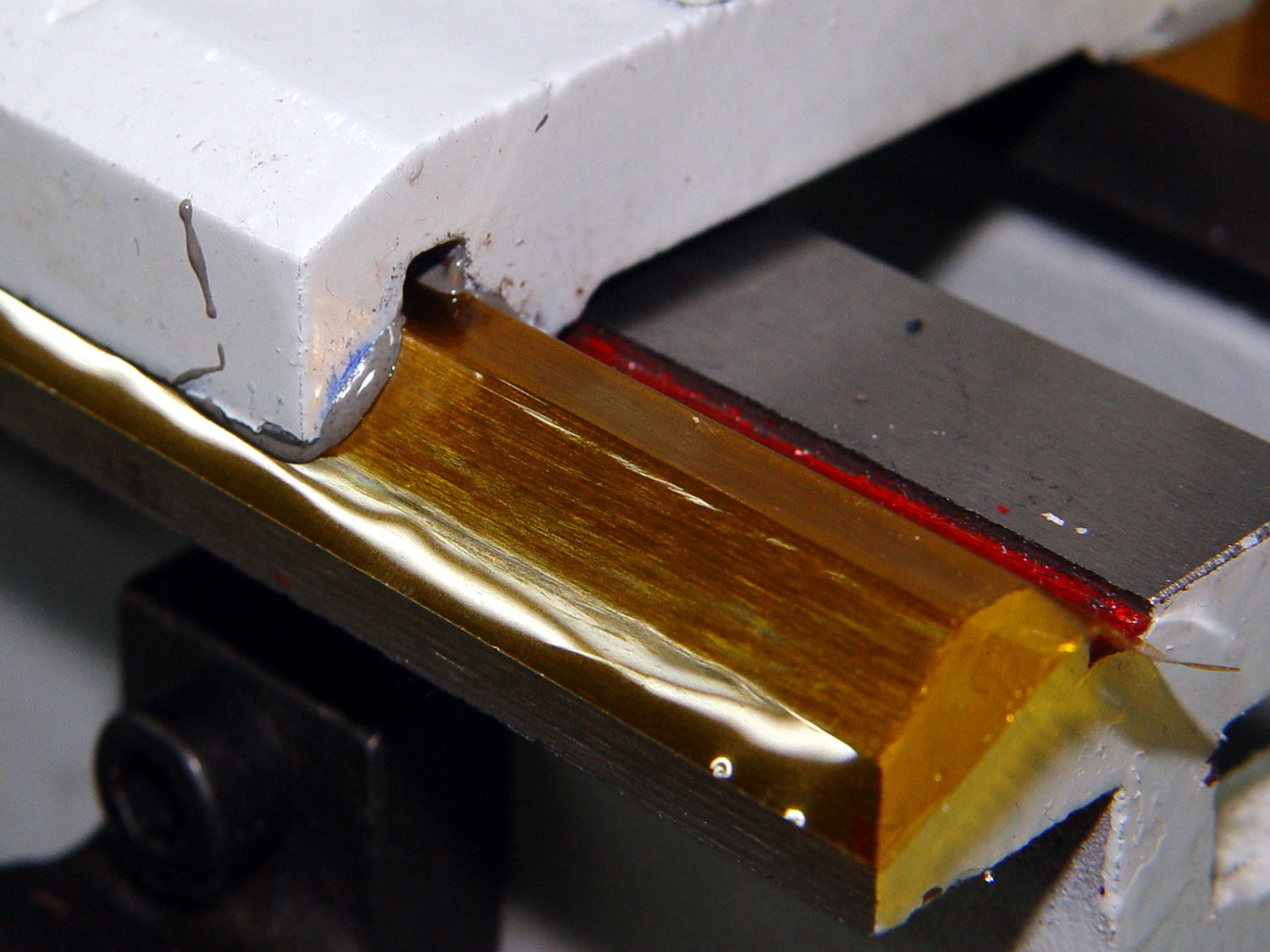
    To prevent permanently affixing the tailstock to the lathe, some folks put a generous layer of oil / graphite / soot / release agent on the lathe bed ways. I used some 3 mil = 0.08 mm Kapton tape, figuring an impervious layer would pretty much guarantee I could get the tailstock off again, no matter what.

    So, we begin.

    Butter up the tailstock ways with epoxy and smoosh into place atop the Kapton:

    Tailstock way repair - V groove on tape
    Tailstock way repair – V groove on tape

    Make sure the tailstock remains well-seated where it should be:

    Tailstock way repair - weights
    Tailstock way repair – weights

    Do other things for 24 hours while the epoxy cures, pry the tailstock loose by hammering The Giant Prying Screwdriver between the lathe bed and the underside of the tailstock (just right of the V-groove, where nothing slides on the bed, but I did use a bit of plastic as a shield), chip off excess epoxy, clean things up, etc, etc.

    This time, I applied Sharpie to the lathe bed, then slid the tailstock back & forth a few times. As a result, the blue areas now show the contact patches and the gray areas just slid by without touching.

    The flat way looks pretty good:

    Tailstock way repair - flat epoxy blued
    Tailstock way repair – flat epoxy blued

    That round dot over on the right seems to be a steel protrusion; I think it’s part of the same lump appearing in the “before” picture above. That rather sharp point seems to have indented the tape and produced a low area in the epoxy around it, which may not matter much: it was the only contact point before I did this.

    The V groove isn’t anywhere near perfect:

    Tailstock way repair - V groove epoxy blued
    Tailstock way repair – V groove epoxy blued

    On the upside, the ways have much, much larger contact patches spread across nearly their entire lengths, which isn’t to be sniffed at.

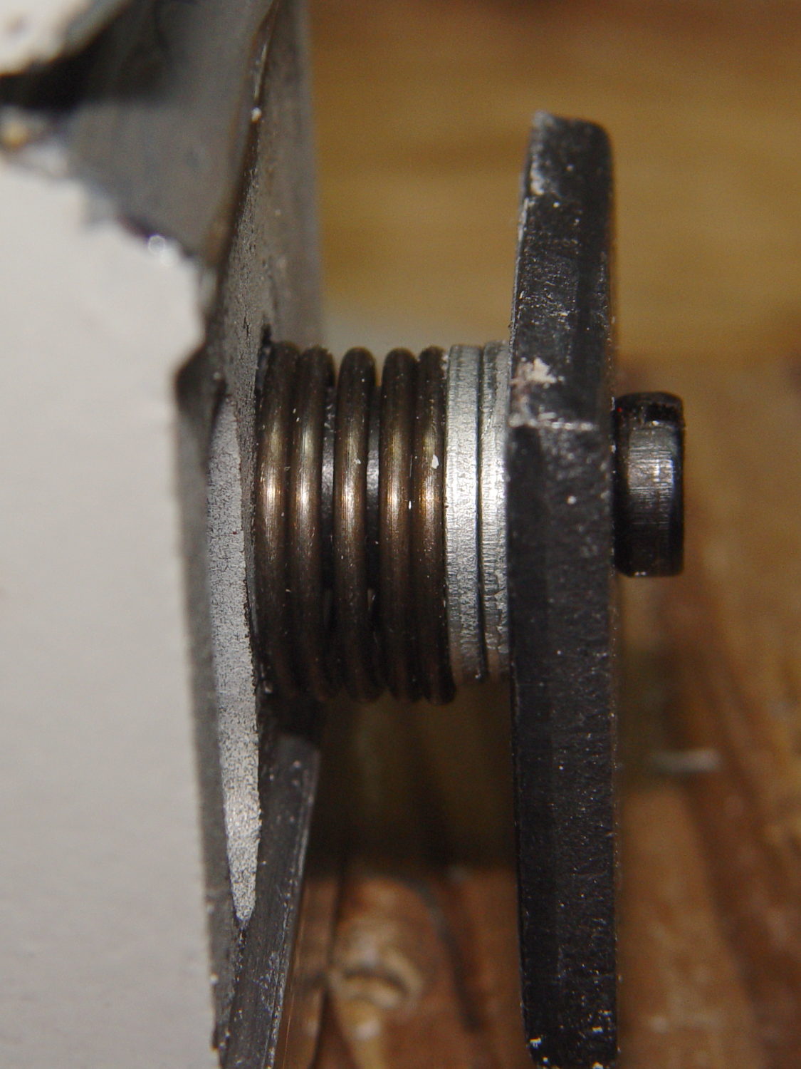
    While reassembling the tailstock, I added a pair of M6 washers above the clamp plate so it cleared the bed with the screw tightened into the cam-lock post:

    Tailstock clamp plate - washers
    Tailstock clamp plate – washers

    Which definitely calls for a small bushing, of course. If you put a lockwasher under the screw head, it won’t clear the end of the bed casting. So it goes.

    Another washer under the ram lock screw changed the phase enough to keep the knob out of the way in both the fully locked and unlocked positions:

    Tailstock ram lock - added washer
    Tailstock ram lock – added washer

    I slobbered some Mobil Vactra #2 Sticky Way Oil (thanks, Eks!) on the bed ways, snuggled the tailstock in place, and wow does that thing move! Verily, it slides smoothly and clamps solidly in place: a tremendous improvement over the status quo ante.

    Some observations…

    • The tape (perhaps the adhesive layer) produces a slightly textured epoxy surface
    • The tailstock way’s small contact points indented the tape, even though it’s only 3 mil thick
    • Filling the low areas in the way works well
    • The high areas may not have enough epoxy for good durability
    • I expect the epoxy will wear faster than steel, so contact should improve with time
    • This is not a permanent fix

    What I’ll do differently next time…

    • Apply more epoxy to avoid those small gaps along the edges
    • Use a real release agent: smoothed in place, it might provide a better finish. Might not matter
    • Verify a good prying spot before epoxying, say, the compound

    All in all, though, this worked much better than I expected!

  • Vacuum Tube Lights: Plate Wire Plug

    After replacing the WS2812 LED in the 21HB5A socket, I drilled out the hole in the disk platter for a 3.5 mm stereo jack, wired a nice knurled metal plug onto the plate lead, and it’s all good:

    21HB5A - Audio plug cable
    21HB5A – Audio plug cable

    The plug had a rather large cable entry that cried out for a touch of brass:

    Audio plug - brass trim turning
    Audio plug – brass trim turning

    Fancy plugs have a helical spring strain relief insert about the size & shape of that brass snout; might have to buy me some fancy plugs.

    This time, I got the alignment right by clamping everything in the lathe while the epoxy cured:

    Audio plug - brass trim gluing
    Audio plug – brass trim gluing

    I flipped the drill end-for-end, which was surely unnecessary.

    It’s now sitting on the kitchen table, providing a bit of light during supper while I wait for a WS2812 controller failure. Again.

  • Screw Cutting Fixture vs. Lathe Ways

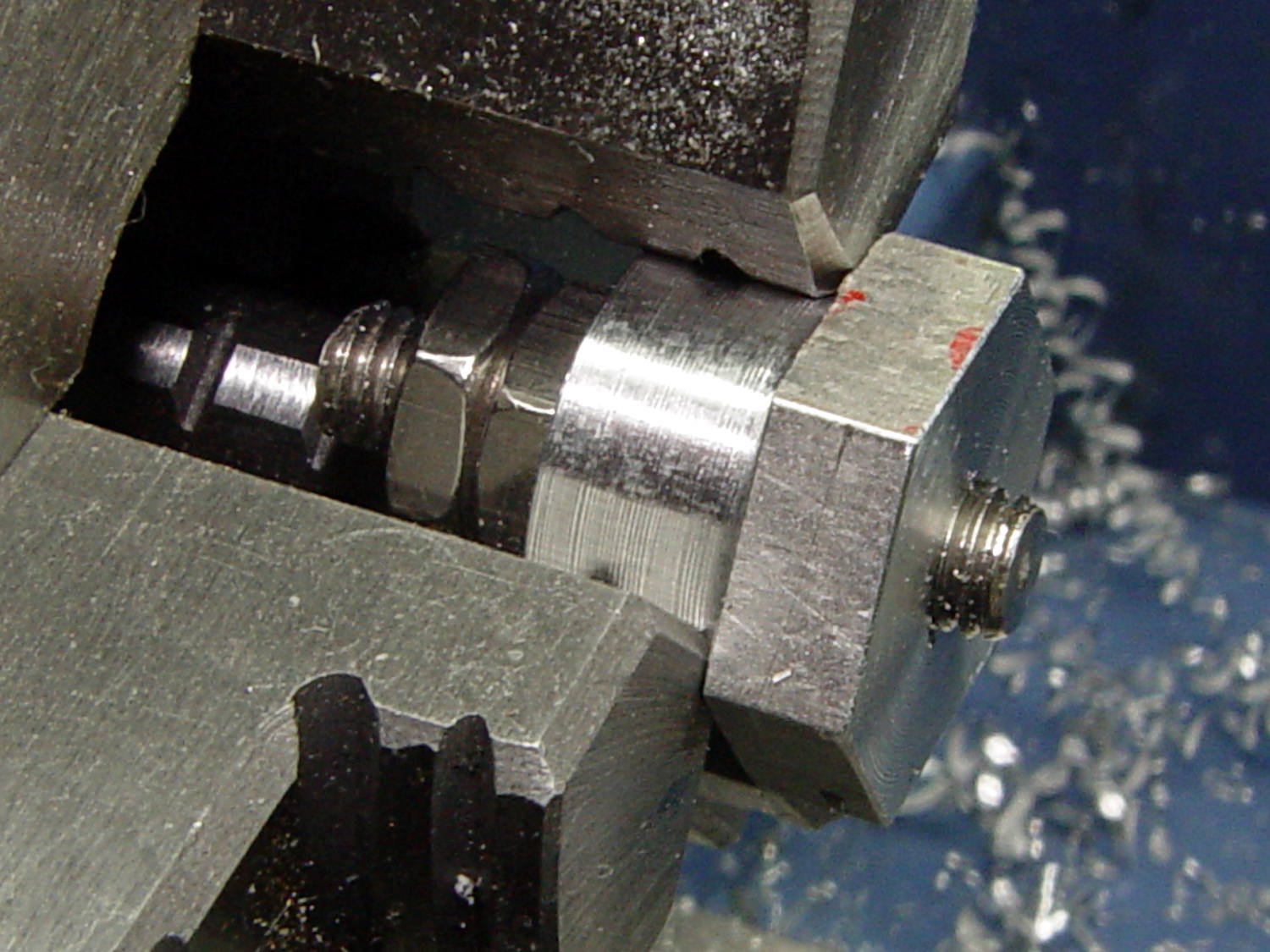
    A length of aluminum hex bar became a nice 10-32 screw trimmer:

    Screw cutting fixture - 10-32 - first cut
    Screw cutting fixture – 10-32 – first cut

    The hex neatly fits a 5/8 inch wrench, so I can tighten the jam nuts enough to run the lathe forward, part off the screw, and clean up the end just fine.

    Unfortunately, the second test cut didn’t work nearly so well:

    Screw cutting fixture - 10-32 - wrecked
    Screw cutting fixture – 10-32 – wrecked

    With the cross-slide gib adjusted to the snug side of easy, the cut put enough pressure on the parting tool to lift the way on the tailstock side about 4 mil = 0.1 mm. The parting tool submarined under the cut, dislodged the fixture, and didn’t quite stall the motor while the chuck jaws ate into the aluminum.

    Well, that was a learning experience.

    After tightening the cross-slide gib to the far side of hard-to-turn:

    • Put a longer screw in the fixture
    • Grab it in the tailstock drill chuck
    • Crunch the hex end of the fixture in the spindle chuck
    • Remove the screw through the spindle (*)
    • Put a slight taper on the end of the fixture threads with a center drill
    • Deploy the live center to support the fixture

    Like this:

    Screw cutting fixture - 10-32 - rechucked
    Screw cutting fixture – 10-32 – rechucked

    Turns out that angling the bit by 10° dramatically reduces chatter. If I had BR and BL turning tools, I’d be using them with the QCTP set to 0°, but they weren’t included in the set that came with the lathe.

    It’s a good thing I’m not fussy about the diameter of that cylindrical section:

    Screw cutting fixture - 10-32 - reshaped
    Screw cutting fixture – 10-32 – reshaped

    I knew the craptastic lathe ways needed, mmmm, improvement and it’s about time to do something.

    (*) By concatenating all my ¼ inch socket extension bars into an absurd noodle capped with square-to-hex adapter holding a Philips bit.

  • Screw Cutting Fixture: Full-thread Aluminum

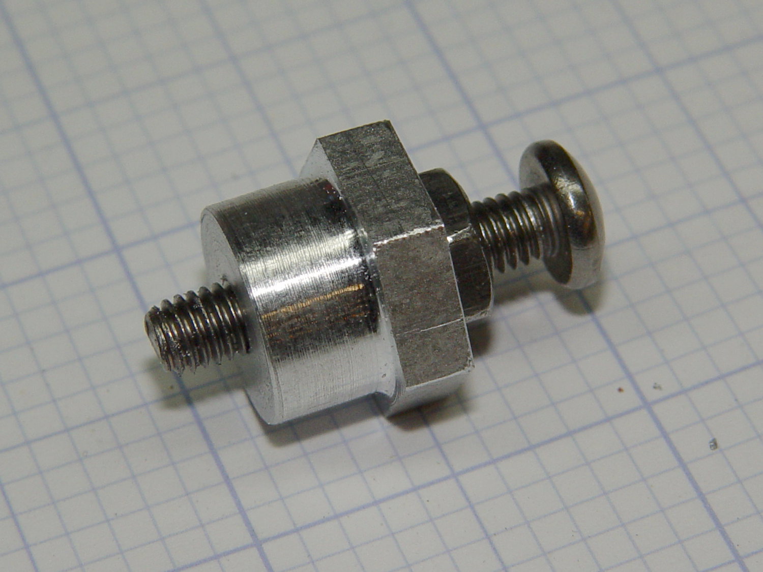
    By and large, when you follow the recipe, you get the expected result:

    Screw cutting fixture - M3x0.5 aluminum - side view
    Screw cutting fixture – M3x0.5 aluminum – side view

    That’s another length of the same aluminum rod, this time with a full-length M3x0.5 thread down the middle, and a screw with a neatly trimmed end.

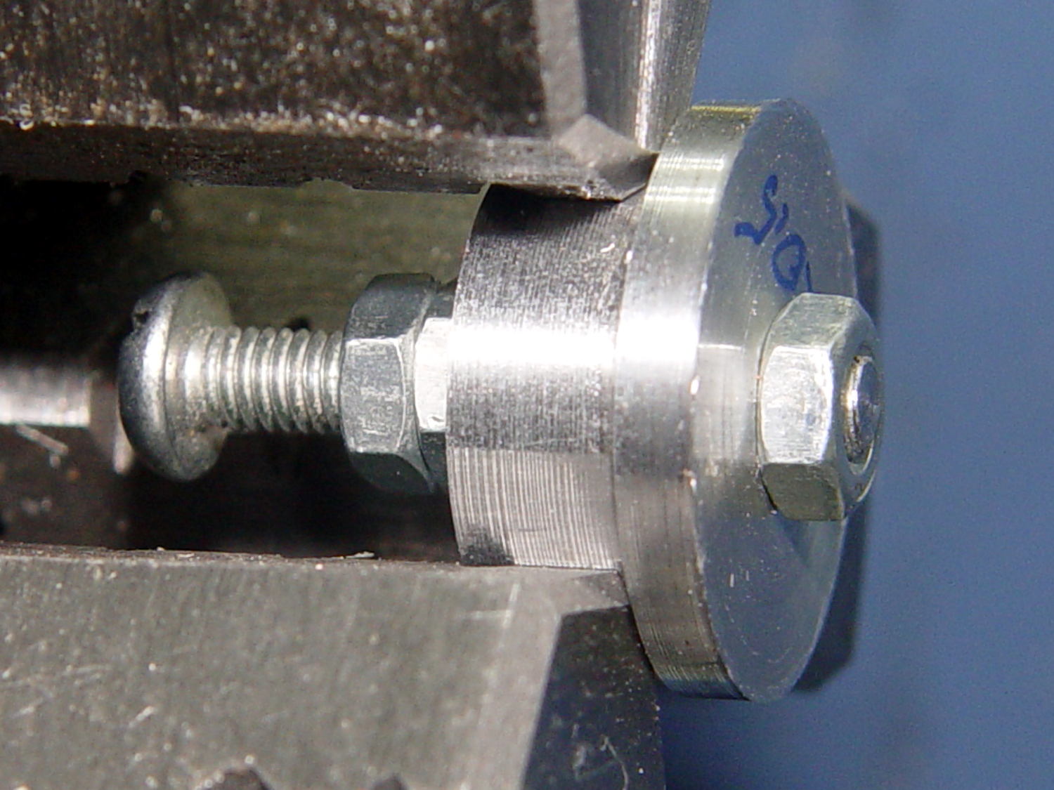
    Running the lathe spindle in reverse prevents the screw from loosening the jam nuts on the left:

    Screw cutting fixture - M3x0.5 aluminum - in lathe chuck
    Screw cutting fixture – M3x0.5 aluminum – in lathe chuck

    Running the spindle forward does move the screw enough to loosen the nuts. Perhaps I should put wrench flats on the big end of the fixture so I can really torque the nuts.

    That front nut was mostly decorative, rather than tight, because I didn’t expect the first attempt to work nearly as well as it did. A bit of filing to taper the end of the thread and it was all good.

    That was easy…


  • Kenmore 158: Presser Foot Tweak

    After watching Mary fiddle with the shrunken presser foot screw, I tapered the tip as a guide into the hole:

    Presser Foot Screw - tapered tip
    Presser Foot Screw – tapered tip

    A hint-and-tip (which I cannot, alas, find again) suggested making bushings to simplify trimming screws in the lathe. A rim on the bushing aligns it with the front of the jaws, the screw threads into the central hole with a jam nut locking it in place, then you can turn / shape / file the end of the screw just beyond bushing with great support and a total lack of drama.

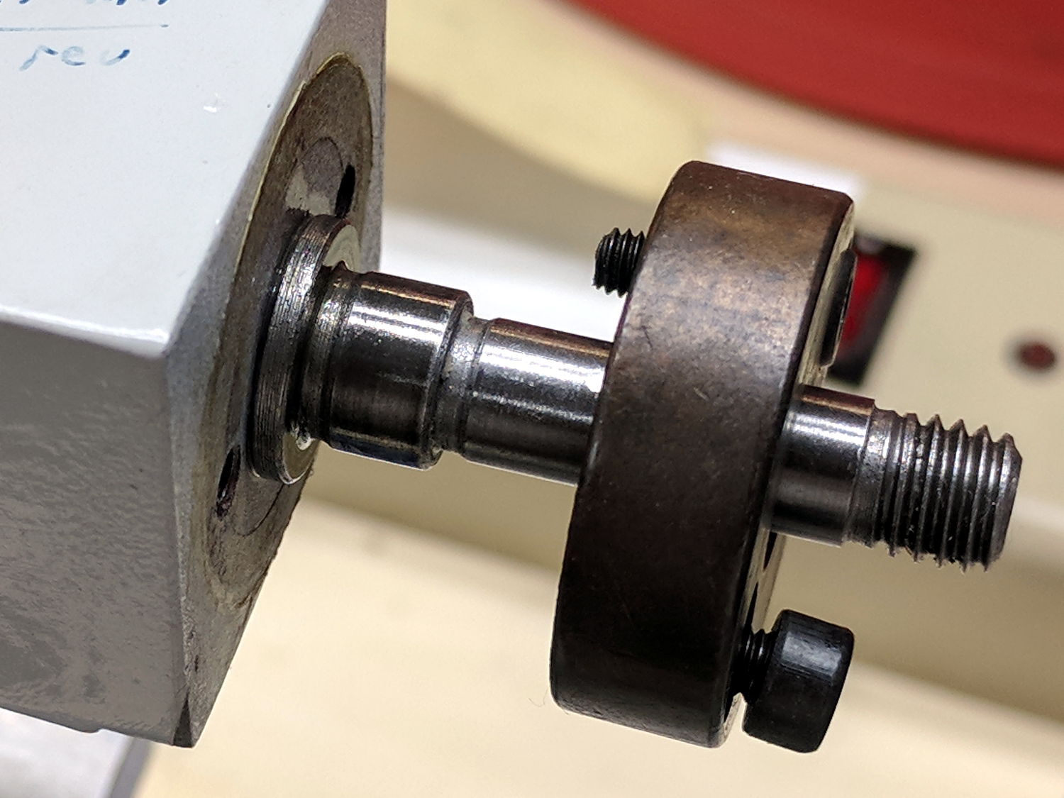
    For the moment, I just aligned the screw in the tailstock drill chuck, crunched the three-jaw spindle chuck on the screw head, backed off the tailstock, took unsupported sissy cuts, and it was all good:

    Presser Foot Screw - chuck alignment
    Presser Foot Screw – chuck alignment

    Gotta make those bushings!

  • Respooling Stainless Steel Thread: The Knack

    The comments on my previous stainless-steel thread respooling attempt suggested that I was entirely too much of a sissy, so, when another empty spool appeared, I tried again with more vigor:

    Stainless steel thread - second spool
    Stainless steel thread – second spool

    As before, I put the larger spool on the floor under the lathe and let the thread spill straight off the top toward the smaller spool. This time, I didn’t have a twist accumulating in the loose thread between the two spools:

    • Grab longer lengths of the loose thread
    • Absolutely no slippage between the fingers!
    • Put more tension on the thread at the takeup spool

    As nearly as I can tell, the thread still has a slight twist coming off the larger spool, but grabbing longer lengths captures the twist and more tension lays it on the smaller spool. After cutting the thread, what was left had maybe three turns of twist, which was no big deal and obviously hadn’t accumulated.

    Seems better: thanks for all the comments!

  • Fordham FG-801 Function Generator Power Switch

    The power switch in my trusty Fordham FG-801 Function Generator failed with an accumulation of oxidation / crud on the contacts. That’s fix-able, but the switch contained not one, but two powerful springs, and puked its guts all over the floor around the Squidwrench Operating Table. Even with (a preponderance of) the parts in hand, I couldn’t figure out how to reassemble the thing; the only way out was to replace the switch.

    The OEM switch had a 0.360+ inch diameter pushbutton that fit into a ⅜ inch hole and, alas, my remaining stock of line-voltage switches had toggle levers and used ¼ inch holes. So I converted a bit of aluminum rod into a suitable bushing:

    Fordham FG-801 Fn Gen - new switch hardware
    Fordham FG-801 Fn Gen – new switch hardware

    The lock washer in the middle started with a much wider tab that I filed down into a tooth for the dent from a #2 center drill. Protip: center drills don’t walk off like twist drills, even when you hand-hold the front panel at the drill press with all the electronics dangling below.

    The bushing dimension doodle:

    Fordham FG-801 Function Generator - Replacement Switch Bushing
    Fordham FG-801 Function Generator – Replacement Switch Bushing

    The internal wiring routes the 120 VAC line conductor to the switch, then to the fuse, then to the transformer. I don’t know whether it’s better to have an unfused switch or an unswitched fuse (surely there’s a UL spec for that), but I didn’t change anything. The new switch, being slightly smaller and mounting directly on the panel, required a new wire (the blue one) from the fuse:

    Fordham FG-801 Fn Gen - power switch - installed
    Fordham FG-801 Fn Gen – power switch – installed

    The OEM switch mounted on two round brass standoffs and, wonder to tell, the new switch fit between them!

    From the front, the new switch looks like it grew there:

    Fordham FG-801 Fn Gen - switch in action
    Fordham FG-801 Fn Gen – switch in action

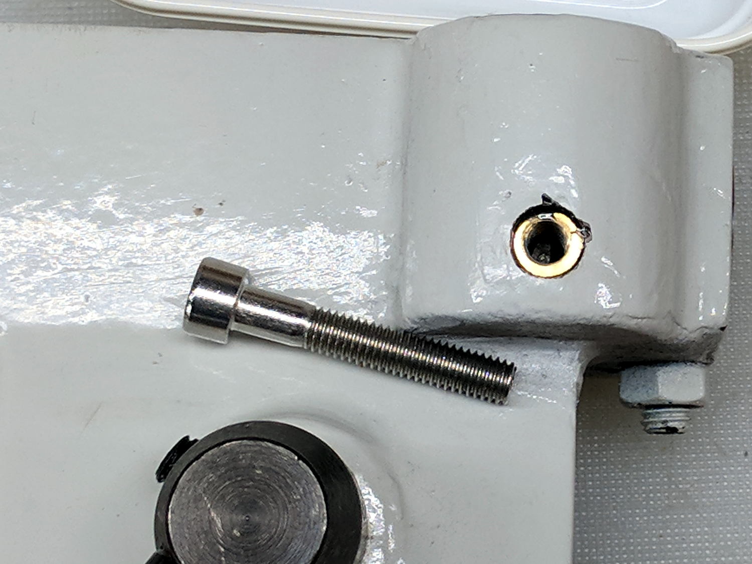
    The PCB mounts to the top of the case with one screw and four hexagonal brass standoffs. The standoffs have 6-32 tapped holes on one end and a 6-32 stud on the other; one of those stud had broken off. A 6-32 stainless steel screw secured in a clearance hole with a dab of epoxy solved that problem:

    Fordham FG-801 Fn Gen - standoff stud
    Fordham FG-801 Fn Gen – standoff stud

    I stood it vertically and tweaked the screw to be perpendicular while the epoxy cured.

    Memo to Self: The next time around, put a nut on the stud to make sure the answer comes out right. I didn’t do this time to avoid epoxying the nut to the standoff.

    Done!