Ed Nisley's Blog: Shop notes, electronics, firmware, machinery, 3D printing, laser cuttery, and curiosities. Contents: 100% human thinking, 0% AI slop.
If I were doing it, I’d add 1.75 mm alignment holes in each part, but clamping each phalange in both directions came out close enough:
Anthromod Finger – clamping
The tolerances were a bit tight and it required some trimming before all the joints flexed freely. I used short segments of 3 mm orange filament for the knuckle hinges and heat-staked the ends, rather than having to trim a trio of 3 mm screws:
Anthromod Finger – detail
After making three short rubber bands by tying and trimming loops from a longer band, the finger curled up just like yours:
Anthromod Finger – curled
The overall quality isn’t as good as I’d like: there’s a bit of uplift on the edges and corners. If I print another one, I want to try less than 0.2 infill and less cooling.
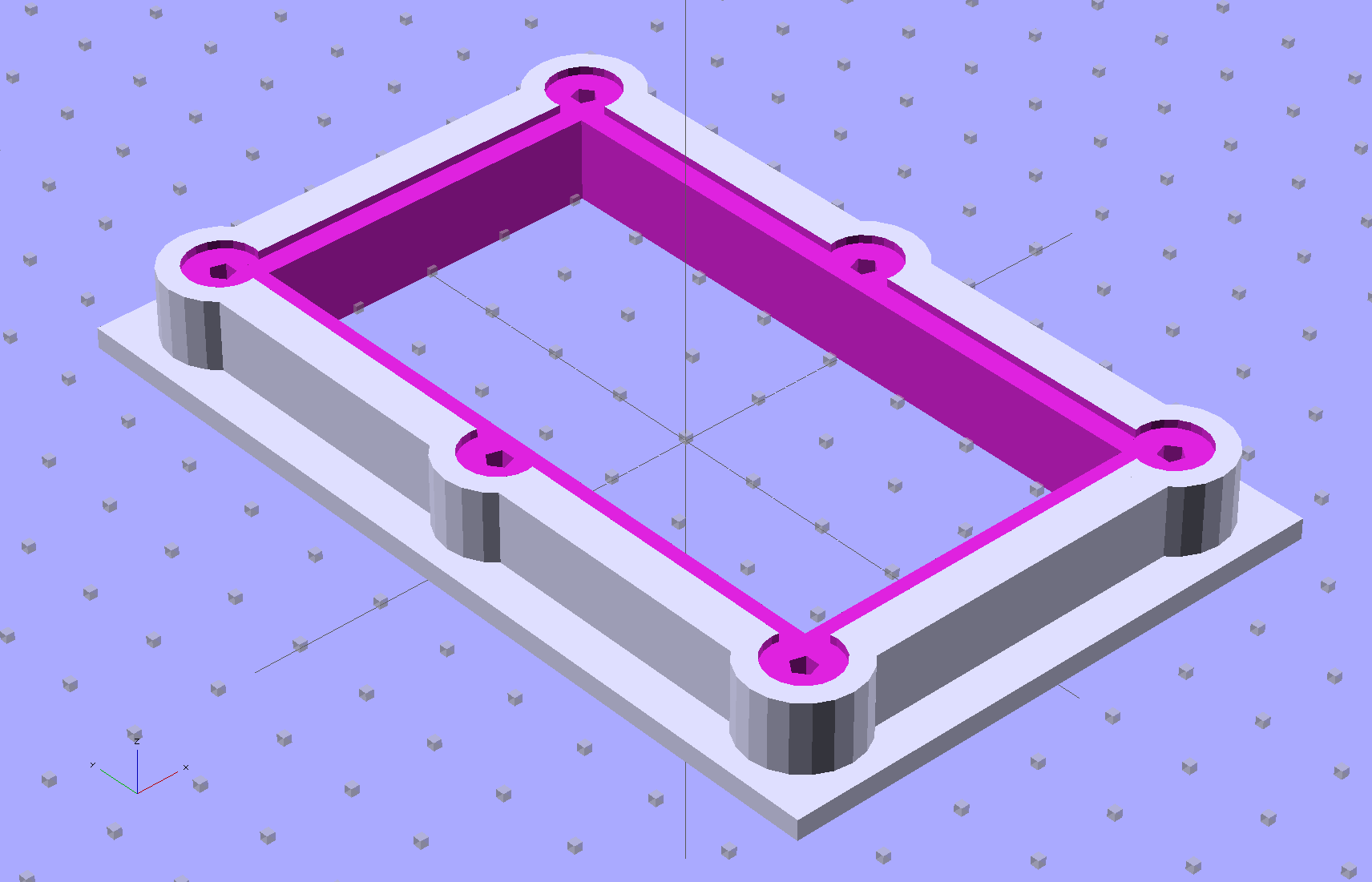
The brassboard PCB for the Hall effect blinky light is too bendy for the SMD parts to survive much debugging, particularly with all the wires hanging off the edges, so I whipped up a stiff mounting bracket that captures the whole thing, with a flange that fits in the work stand arms:
PCB Test Frame – solid model
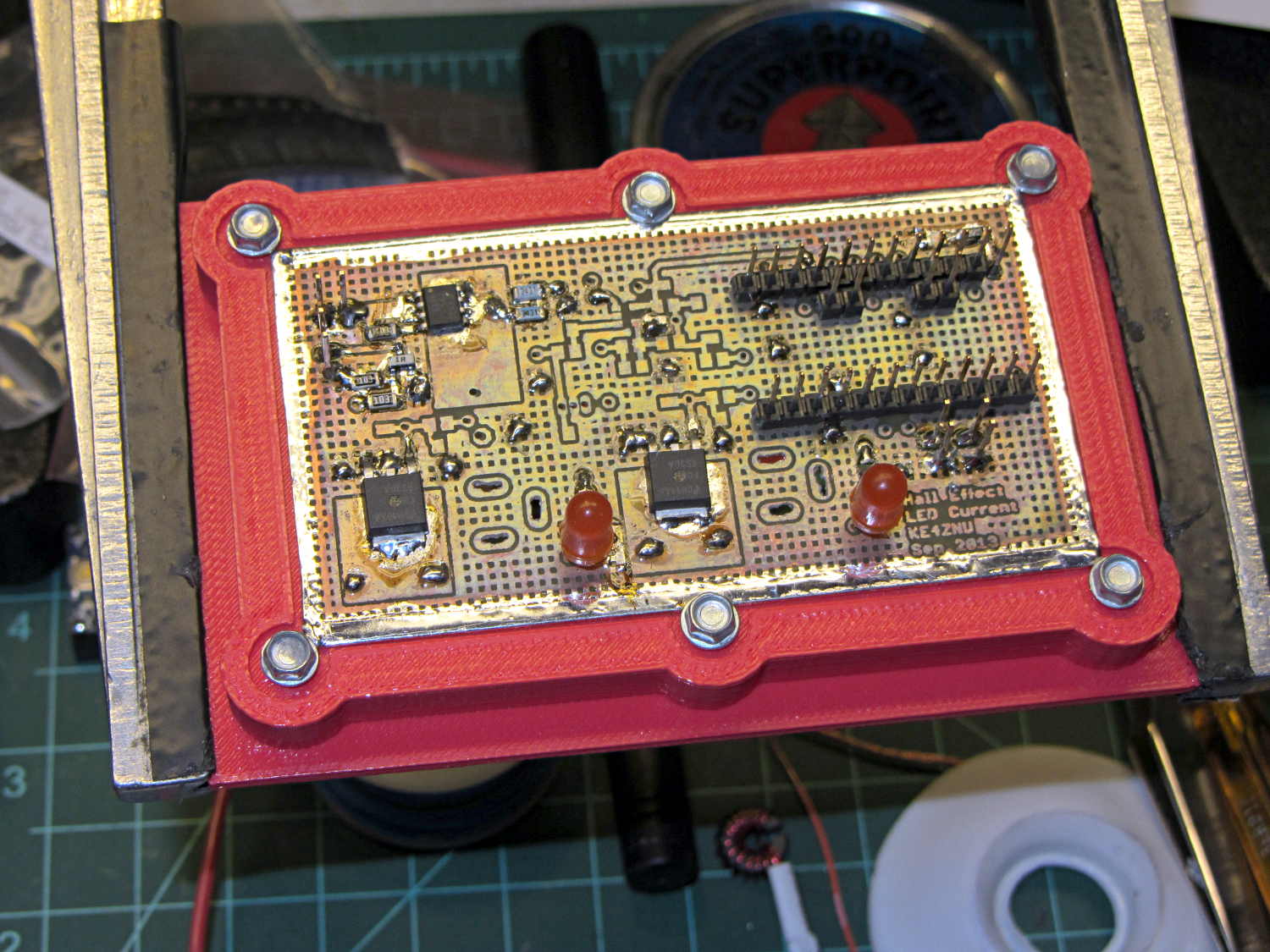
I ran some self-tapping 4-40 hex-head screws into the holes while the plastic was still warm on the M2’s platform:
PCB stiffener with screws on M2 platform
Six screws seem excessive and I’ll probably wind up using just the middle two, but there’s no harm in having more holes and fittings than you really need.
The flange fits neatly into the board holder on the Electronics Workbench, above all the construction clutter:
PCB stiffener in board holder
The nice thing about having a 3D printer: when you need an object like this, a couple of hours later you have one!
The OpenSCAD source code, slightly improved based the results you see above:
// Test support frame for Hall Effect LED Blinky Light
// Ed Nisley KE4ZNU - Sept 2013

ClampFlange = true;

//- Extrusion parameters - must match reality!

ThreadThick = 0.25;
ThreadWidth = 0.40;

function IntegerMultiple(Size,Unit) = Unit * ceil(Size / Unit);

Protrusion = 0.1;

HoleWindage = 0.2;

//- Screw sizes

inch = 25.4;

Tap4_40 = 0.089 * inch;
Clear4_40 = 0.110 * inch;
Head4_40 = 0.211 * inch;
Head4_40Thick = 0.065 * inch;
Nut4_40Dia = 0.228 * inch;
Nut4_40Thick = 0.086 * inch;
Washer4_40OD = 0.270 * inch;
Washer4_40ID = 0.123 * inch;

//- PCB sizes

PCBSize = [46.5,84.0,1.0];
PCBShelf = 2.0;

Clearance = 4*[ThreadWidth,ThreadWidth,0];

WallThick = IntegerMultiple(4.0,ThreadWidth);
FrameHeight = 5.0;

ScrewOffset = 0.0 + Clear4_40/2;

OAHeight = FrameHeight + Clearance[2] + PCBSize[2];

FlangeExtension = 3.0;
FlangeThick = IntegerMultiple(1.5,ThreadThick);
Flange = PCBSize
			+ 2*[ScrewOffset,ScrewOffset,0]
			+ 2*[Washer4_40OD,Washer4_40OD,0]
			+ [2*FlangeExtension,2*FlangeExtension,(FlangeThick - PCBSize[2])]
			;

echo("Flange: ",Flange);
NumSides = 4*5;

//- Adjust hole diameter to make the size come out right

module PolyCyl(Dia,Height,ForceSides=0) {			// based on nophead's polyholes

  Sides = (ForceSides != 0) ? ForceSides : (ceil(Dia) + 2);

  FixDia = Dia / cos(180/Sides);

  cylinder(r=(FixDia + HoleWindage)/2,h=Height,$fn=Sides);
}

//- Put peg grid on build surface

module ShowPegGrid(Space = 10.0,Size = 1.0) {

  RangeX = floor(100 / Space);
  RangeY = floor(125 / Space);

	for (x=[-RangeX:RangeX])
	  for (y=[-RangeY:RangeY])
		translate([x*Space,y*Space,Size/2])
		  %cube(Size,center=true);

}

//- Build it

ShowPegGrid();

difference() {
	union() {									// body block and screw bosses
		translate([0,0,OAHeight/2])
			color("LightBlue")
			cube(PCBSize + Clearance + [2*WallThick,2*WallThick,FrameHeight],center=true);
		for (x=[-1,1], y=[-1,0,1]) {
			translate([x*(PCBSize[0]/2 + ScrewOffset),
						y*(PCBSize[1]/2 + ScrewOffset),
						0])
				color("Orchid") cylinder(r=Washer4_40OD,h=OAHeight,$fn=NumSides);
		}
		if (ClampFlange)
			translate([0,0,Flange[2]/2])
			color("SeaGreen") cube(Flange,center=true);
	}

	for (x=[-1,1], y=[-1,0,1]) {				// screw holes and washer recesses
		translate([x*(PCBSize[0]/2 + ScrewOffset),
					y*(PCBSize[1]/2 + ScrewOffset),
					-Protrusion])
			rotate((x-1)*90)
			PolyCyl(Tap4_40,(OAHeight + 2*Protrusion));
		translate([x*(PCBSize[0]/2 + ScrewOffset),
					y*(PCBSize[1]/2 + ScrewOffset),
					OAHeight - PCBSize[2]])
			PolyCyl(1.2*Washer4_40OD,(PCBSize[2] + Protrusion),NumSides);
	}

	translate([0,0,OAHeight/2])					// through hole below PCB
		cube(PCBSize - 2*[PCBShelf,PCBShelf,0] + [0,0,2*OAHeight],center=true);

	translate([0,0,(OAHeight - (PCBSize[2] + Clearance[2])/2 + Protrusion/2)])	// PCB pocket on top
		cube(PCBSize + Clearance + [0,0,Protrusion],center=true);
}
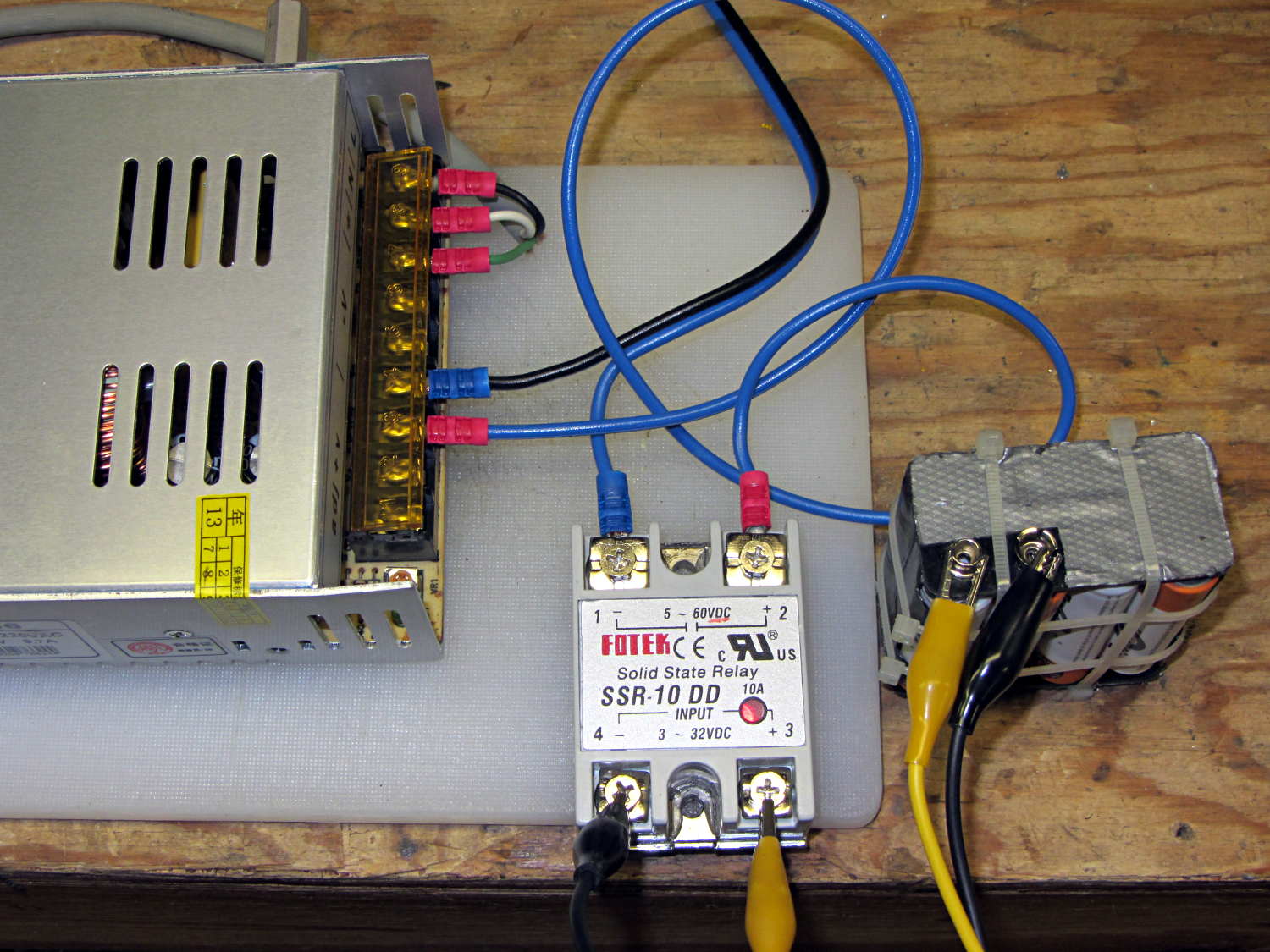
The 36 V supply has the same M4 mount points as the 24 V supply, so I cut up another pair of those long 6-32 threaded standoffs to make four mounts. This time, instead of meticulously drilling-and-tapping the M4 holes, I just poked a clearance hole in the end of each stud with a #23 drill (0.154 = 3.9 mm) that came out a nice slip fit, cut the heads off another quartet of M4 screws (actually, a quintet, as there’s now one stud lost in the lathe swarf), dabbed some JB Quik epoxy in the holes, and rammed the studs in place:
Power supply brick – M4 stud standoffs
Pause for a while and it’s all good. If the epoxy loses traction with the supply hanging from the mounts, it’ll be pretty obvious…
For what it’s worth, the studs come from an M4 hex-and-Philips screws used in some PC cases (The more common M3 screw doesn’t work here, but I think I bought ’em from the same source) . Cheap and readily available, but chrome plated and murder on saw blades; I use an abrasive cutoff wheel. A quartet of equally standard 6-32 PC case screws hold the mounts to the top of the PC case…
[Update: The talk went well and took a bit under three hours, although by mutual agreement we didn’t fire up the M2 at the end. I’ll work on a short talk about Design for Printability and we’ll run that with a separate printing session. A good time was had by all!]
The 36 V 350 W power brick for the improved M2 HBP arrived and seems to work fine, apart from a distinct smell of hot electronics under load. Dialed back to 30.1 V at the terminals (to match the HBP spec) and with the HBP connected through the same length of 12 AWG wire as before, the supply draws 150 W from the AC line.
It draws 160 W at 31.7 V and stabilizes at about 100 °C. The heater resistance is 7.6 Ω before it has a chance to cool off, so the heater runs at 4.17 A and 132 W. The supply efficiency is 83% = 132/160, about what you’d expect. The fan runs intermittently with that load.
In order to dissipate 150 W in the panel at the same resistance, the voltage must be 33.5 V at 4.5 A. I’d want to install it in the M2 and make some measurements before jumping to any conclusions.
The SSR’s forward drop runs around 1.0 to 1.1 V at 4 A, which suggests a drain-source resistance near 0.25 Ω, rather more than you’d expect for a bare MOSFET, but probably about right for an up-armored device. Or it could just be a crap MOSFET inside there…
So I think the brick will wind up at about 35 V to make up for the SSR drop. The SSR will dissipate about 5 W and won’t need much heatsinking; just bolting it to an aluminum chassis may suffice.
Part of the Curvelicious Cookie Cutter effort involved making the thinnest possible cutter blade wall consisting of two adjacent threads, because that’s about what the Afinia printer was producing (from a different model). My OpenSCAD code, based on an Inkscape model derived from the as-printed Afinia cutter, enlarges the cookie shape by a specific distance with a Minkowski sum; the model ultimately becomes G-Code directing the extruder nozzle around the outline.
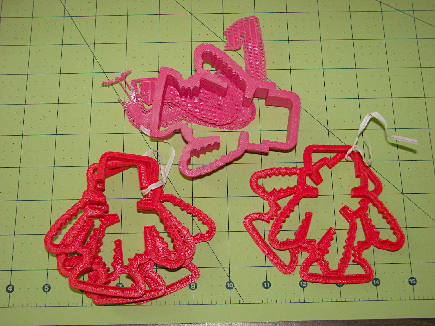
Obviously, that required a bit of fiddling:
Robot Cutter Variations
The pink cutter on the top came from the Afinia, complete with raft. The red cutters, all with short blades to speed up the printing, came from my M2.
The printer mechanics determine the step/mm values for all four axes: X, Y, Z, and the extruder. The effective diameter of the “gear” driving the filament into the extruder seems subject to some quibbling, but setting it so the thinwall box comes out with the proper filament width seems reasonable. Given those four values, the slicing software can control the extruder speed to produce the proper volume of plastic as the XY speed varies.
The slicing software must also know the raw filament diameter, which seems to be consistent within a few percent for the filaments in my collection. Because a 1% change in filament diameter produces a 3% change in extruded volume, a few percent is about all you can tolerate; broad-tolerance filament may require sensors and adjustments that printers don’t currently offer.
There is one remaining variable, essentially a Fudge Factor, which Slic3r calls the extrusion multiplier. This seems to be a linear factor applied to the extrusion volume, so that increasing the factor proportionally increase the flow rate. Given correct step/mm settings and the measured filament diameter, you (well, I) adjust the extrusion multiplier to get the proper extrusion flow. As it turned out, the multiplier I’ve been using with the M2 worked out to 1.00, although I’ve also used 0.97 on occasion. Although I haven’t read the Slic3r source code to verify this, varying the multiplier by +3% should fudge the diameter by about +0.017 mm = 1% of the measured 1.72 mm.
Note that the Makergear-modified Marlin firmware in the M2 will produce different results, as they use a different value for the extruder gear’s effective diameter. More discussion on that is there.
Soooo, I set up the extrusion multiplier to produce parts with accurate dimensions, because that’s what I care about, and didn’t worry too much about perfect surface finish, because I don’t really care about that. Cookie cutters, however, need a completely filled surface that prevents dough from collecting inside, but have essentially no dimensional accuracy requirements.
The quartet of stumpy cutters bundled together on the left of the top photo explored the effect of changing the extrusion multiplier. I used the same STL model for all the cutters and varied only the extrusion factor, so the results depend only on the plastic flow rate and the M2’s impeccable mechanical stability.
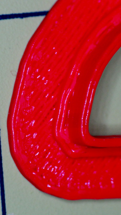
A sharp cusp at 0.96 has a slight opening:
Robot Cutter – 0.96 extrusion multiplier
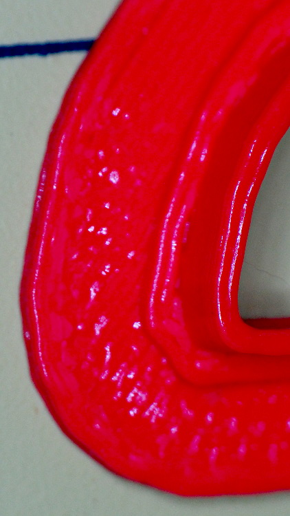
The cusp fills in at 1.10:
Robot Cutter – 1.10 extrusion multiplier
The handle surface is slightly open at 0.96:
Robot Cutter – 0.96 extrusion multiplier
And filled in at 1.10:
Robot Cutter – 1.10 extrusion multiplier
In all those cases, the measured blade thickness varied slightly, but not enough to matter in this application. I didn’t record those numbers and no longer have the models, but … you just tune for best picture.
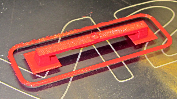
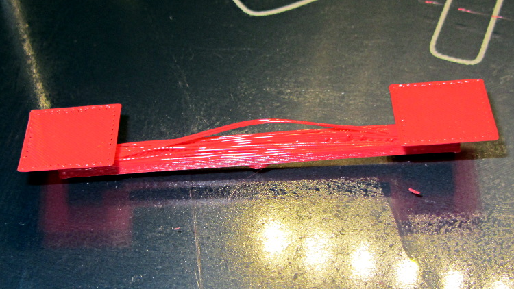
Although I’ve pretty much given up on torture tests, I saw a note about the troubles someone had with Triffid Hunter’s Bridge Torture Test object. I did a bit of tweaking to the OpenSCAD source to shorten the struts and add the pads (which could be done with Slic3r’s Brim settings), but it’s otherwise about the same. The clear span is about 50 mm:
Bridge Torture Test – solid model
Using my usual settings, with no special setup, the front looked OK:
Bridge torture test – overview
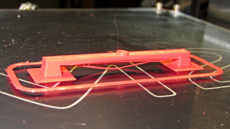
One strand came out rather droopy:
Bridge torture test – front
The bottom layer of the bridge isn’t as consolidated as it could be:
Bridge torture test – bottom
The overall speed dropped considerably as the Cool setting limited the layer time to 20 seconds; the Bridge settings didn’t apply.
I could probably tighten the bottom strands a bit, but it’s OK for a first pass.