The Smell of Molten Projects in the Morning

Ed Nisley's Blog: Shop notes, electronics, firmware, machinery, 3D printing, laser cuttery, and curiosities. Contents: 100% human thinking, 0% AI slop.

Tag: M2

Using and tweaking a Makergear M2 3D printer

  • Makergear M2: Mechanical Setup

    That Slic3r configuration presumes a somewhat nonstandard mechanical setup for my M2…

    I put the XY coordinate origin in the middle of the platform, so that laying objects out for printing doesn’t require knowing how large the platform will be: as long as the printer is Big Enough, you (well, I) can print without further attention.

    The RepRap world puts the XY coordinate origin in the front left corner of the platform, so that the platform size sets the maximum printable coordinates and all printing happens in Quadrant I.  This has the (major, to some folks) advantage of using only positive coordinates, while requiring an offset for each different platform.

    Yes, depending on which printer software you use, you can (automagically) center objects on your platform; this is often the only way to find objects created with Trimble (formerly Google) Sketchup. I am a huge fan of knowing exactly what’s going to happen before the printing starts, so I position my solid models exactly where I want them, right from the start. For example, this OpenSCAD model of the bike helmet mirror parts laid out for printing:

    Helmet mirror mount - 3D model - Show layout
    Helmet mirror mount – 3D model – Show layout

    … exactly matches the plastic on the Thing-O-Matic’s platform, with the XY origin right down the middle of the platform:

    Helmet mirror mount on build platform - smaller mirror shaft
    Helmet mirror mount on build platform – smaller mirror shaft

    It’d print exactly the same, albeit with more space around the edges, on the M2’s platform.

    Similarly, the Z axis origin sits exactly on the surface of the platform. That way, the Z axis coordinate equals the actual height of the current thread extrusion in a measurable way: when you set the Z axis to, say, 2.0 mm, you can measure that exact distance between the extruder nozzle and the platform:

    Taper gauge below nozzle
    Taper gauge below nozzle

    Now, admittedly, I fine-tune that distance by measuring the height of the skirt thread around the printed object, but the principle remains: a thread printed  on the platform with Z=0.25 should be exactly 0.25 mm thick.

    The start.gcode file handles all that:

    ;-- Slic3r Start G-Code for M2 starts --
    ;  Ed Nisley KE4NZU - 15 April 2013
    M140 S[first_layer_bed_temperature]	; start bed heating
    G90				; absolute coordinates
    G21				; millimeters
    M83				; relative extrusion distance
    M84				; disable stepper current
    G4 S3			; allow Z stage to freefall to the floor
    G28 X0			; home X
    G92 X-95			; set origin to 0 = center of plate
    G1 X0 F30000		; origin = clear clamps on Y
    G28 Y0			; home Y
    G92 Y-127 		; set origin to 0 = center of plate
    G1 Y-125 F30000	; set up for prime at front edge
    G28 Z0			; home Z
    G92 Z1.0			; set origin to measured z offset
    M190 S[first_layer_bed_temperature]	; wait for bed to finish heating
    M109 S[first_layer_temperature]	; set extruder temperature and wait
    G1 Z0.0 F2000		; plug extruder on plate
    G1 E10 F300		; prime to get pressure
    G1 Z5 F2000		; rise above blob
    G1 X5 Y-122 F30000	; move away from blob
    G1 Z0.0 F2000		; dab nozzle to remove outer snot
    G4 P1			; pause to clear
    G1 Z0.5 F2000		; clear bed for travel
    ;-- Slic3r Start G-Code ends --
    

    The wipe sequence, down near the bottom, positions the extruder at the front center edge of the glass plate, waits for it to reach the extrusion temperature, then extrudes 10 mm of filament to build up pressure behind the nozzle. The blob generally hangs over the edge of the platform and usually doesn’t follow the nozzle during the next short move and dab to clear the mess:

    M2 - Wipe blobs on glass platform
    M2 – Wipe blobs on glass platform

    I’ve also configured Slic3r to extrude at least 25 mm of filament in at least three passes around the object. After that, the extruder pressure has stabilized and the first layer of the object begins properly.

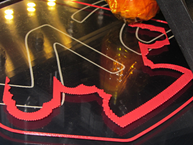
    Which brings up another difference: the first layer printed on the platform is exactly like all the others. It’s not smooshed to get better adhesion or overfilled to make the threads stick together:

    Robot cookie cutter - printing first layer
    Robot cookie cutter – printing first layer

    I print the first layer at 25 mm/s to give the plastic time to bond to the platform and use hairspray to make PLA stick to glass like it’s glued down.

    After that, it’s just ordinary 3D printing…

  • Makergear M2: Slic3r config.ini

    A stick in the ground…

    I think the exported config.ini file corresponds to the currently selected set of sub-configurations; I find it difficult to keep a myriad of selections up-to-date while tweaking things, so mostly I don’t bother with named configurations.

    The start.gcode and end.gcode lines go on forever, with embedded newlines.

    # generated by Slic3r 0.9.11-dev on Mon Jul 22 09:28:22 2013
    avoid_crossing_perimeters = 
    bed_size = 190,250
    bed_temperature = 70
    bottom_solid_layers = 3
    bridge_acceleration = 0
    bridge_fan_speed = 100
    bridge_flow_ratio = 1
    bridge_speed = 150
    brim_width = 0
    complete_objects = 0
    cooling = 1
    default_acceleration = 0
    disable_fan_first_layers = 0
    duplicate = 1
    duplicate_distance = 6
    duplicate_grid = 1,1
    end_gcode = ;-- Slic3r End G-Code for M2 starts --\n;  Ed Nisley KE4NZU - March 2013\nM104 S0		; drop extruder temperature\nM140 S0		; drop bed temperature\nM106 S0		; bed fan off\nG1 Z180 F2000	; lower bed\nG1 X0 Y0 F30000	; center nozzle\nM84     	; disable motors\n;-- Slic3r End G-Code ends --
    external_perimeter_speed = 50
    external_perimeters_first = 0
    extra_perimeters = 1
    extruder_clearance_height = 20
    extruder_clearance_radius = 20
    extruder_offset = 0x0
    extrusion_axis = E
    extrusion_multiplier = .99
    extrusion_width = 0.40
    fan_always_on = 0
    fan_below_layer_time = 45
    filament_diameter = 1.72
    fill_angle = 45
    fill_density = 0.15
    fill_pattern = honeycomb
    first_layer_bed_temperature = 70
    first_layer_extrusion_width = 0
    first_layer_height = 100%
    first_layer_speed = 25
    first_layer_temperature = 175
    g0 = 0
    gap_fill_speed = 50
    gcode_arcs = 0
    gcode_comments = 0
    gcode_flavor = reprap
    infill_acceleration = 0
    infill_every_layers = 1
    infill_extruder = 1
    infill_extrusion_width = 0
    infill_first = 1
    infill_only_where_needed = 1
    infill_speed = 125
    layer_gcode = 
    layer_height = 0.25
    max_fan_speed = 100
    min_fan_speed = 45
    min_print_speed = 15
    min_skirt_length = 25
    notes = 
    nozzle_diameter = 0.35
    only_retract_when_crossing_perimeters = 1
    output_filename_format = [input_filename_base].gcode
    overhangs = 1
    perimeter_acceleration = 0
    perimeter_extruder = 1
    perimeter_extrusion_width = 0
    perimeter_speed = 100
    perimeters = 1
    post_process = 
    print_center = 0,0
    raft_layers = 0
    randomize_start = 1
    resolution = 0
    retract_before_travel = 0.5
    retract_layer_change = 0
    retract_length = 1
    retract_length_toolchange = 5
    retract_lift = 0
    retract_restart_extra = 0
    retract_restart_extra_toolchange = 0
    retract_speed = 80
    rotate = 0
    scale = 1
    skirt_distance = 5
    skirt_height = 1
    skirts = 3
    slowdown_below_layer_time = 20
    small_perimeter_speed = 25
    solid_fill_pattern = rectilinear
    solid_infill_below_area = 15
    solid_infill_every_layers = 0
    solid_infill_extrusion_width = 0
    solid_infill_speed = 100
    spiral_vase = 0
    start_gcode = ;-- Slic3r Start G-Code for M2 starts --\n;  Ed Nisley KE4NZU - 15 April 2013\nM140 S[first_layer_bed_temperature]	; start bed heating\nG90				; absolute coordinates\nG21				; millimeters\nM83				; relative extrusion distance\nM84				; disable stepper current\nG4 S3			; allow Z stage to freefall to the floor\nG28 X0			; home X\nG92 X-95			; set origin to 0 = center of plate\nG1 X0 F30000		; origin = clear clamps on Y\nG28 Y0			; home Y\nG92 Y-127 		; set origin to 0 = center of plate\nG1 Y-125 F30000	; set up for prime at front edge\nG28 Z0			; home Z\nG92 Z1.0			; set origin to measured z offset\nM190 S[first_layer_bed_temperature]	; wait for bed to finish heating\nM109 S[first_layer_temperature]	; set extruder temperature and wait\nG1 Z0.0 F2000		; plug extruder on plate\nG1 E10 F300		; prime to get pressure\nG1 Z5 F2000		; rise above blob\nG1 X5 Y-122 F30000	; move away from blob\nG1 Z0.0 F2000		; dab nozzle to remove outer snot\nG4 P1			; pause to clear\nG1 Z0.5 F2000		; clear bed for travel\n;-- Slic3r Start G-Code ends --
    start_perimeters_at_concave_points = 1
    start_perimeters_at_non_overhang = 1
    support_material = 0
    support_material_angle = 0
    support_material_enforce_layers = 0
    support_material_extruder = 1
    support_material_extrusion_width = 0
    support_material_interface_layers = 0
    support_material_interface_spacing = 0
    support_material_pattern = rectilinear
    support_material_spacing = 2.5
    support_material_speed = 125
    support_material_threshold = 0
    temperature = 175
    thin_walls = 1
    threads = 2
    toolchange_gcode = 
    top_infill_extrusion_width = 0
    top_solid_infill_speed = 50
    top_solid_layers = 3
    travel_speed = 250
    use_relative_e_distances = 0
    vibration_limit = 0
    wipe = 0
    z_offset = 0
    
    
  • Makergear M2: The End of Torture Test Objects

    While pulling together a talk on OpenSCAD modeling (more on this later), I ran off a batch of calibration and “torture test” objects, with the intent of seeing how my somewhat modified M2 performs. The short answer is that you (well, I) can’t ask for anything better…

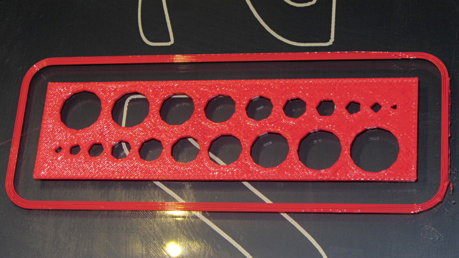
    Using my OpenSCAD module based on nophead’s polyholes to adjust low-vertex polygons by a constant +0.2  mm produces results that are within ±0.1 mm of the nominal value for holes larger than 3.0 mm:

    M2 - Small Hole Calibration Test
    M2 – Small Hole Calibration Test

    That level of as-printed cleanliness is typical: no stringing, no hair, no misplaced globs, no retraction problems. Basically, the plastic shape on the platform matches the mathematical shape on screen.

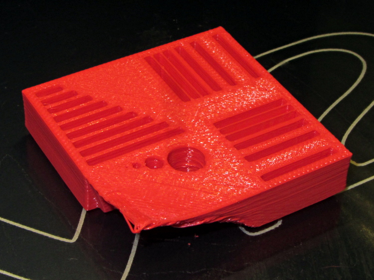
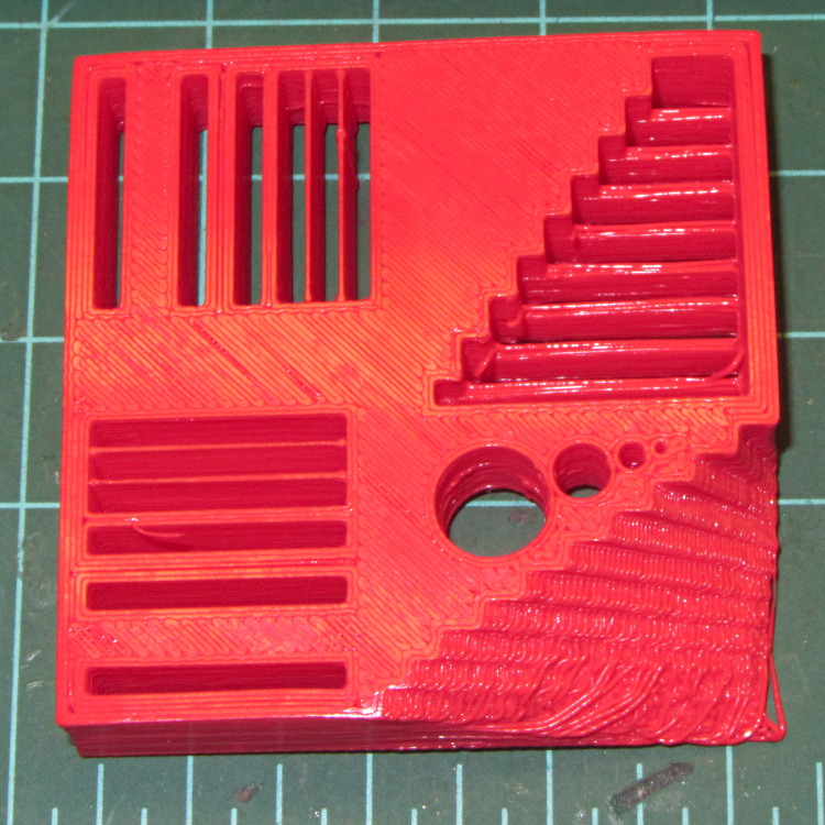
    Goaran’s Calibration Block came out fine, except for the intended-to-be-impossible overhangs:

    M2 - Calibration Block - overview
    M2 – Calibration Block – overview

    All of the linear features are with ±0.1 mm of nominal; both the 0.5 and 0.25 mm walls came out at 0.40 mm, because that’s the thread width. Slic3r doggedly puts a thread down the middle of hair-fine walls, which I think is a Good Thing.

    The holes came out less than 0.3 mm undersize, which is about what you’d expect because they’re not pre-distorted and have far too many sides. The 1.0 and 0.5 mm diameter holes are present, but just barely visible; those simply aren’t reasonable sizes for this technology.

    The bottom view shows a few strings in the bridge test area and more detail of the overhang:

    M2 - Calibration Block - bottom
    M2 – Calibration Block – bottom

    Grouping the overhangs like that produced a flat surface that tended to curl upward, so the final slopes don’t match the design. In round numbers, the M2 can handle something like a 60° overhang reasonably well.

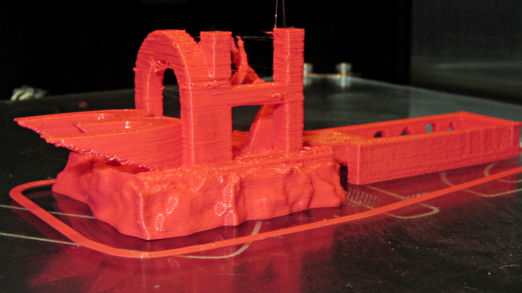
    Cymon’s 3DHacker demo object came out OK, even the severe overhangs in the legs of the digit 3:

    M2 - 3DHacker object - front
    M2 – 3DHacker object – front

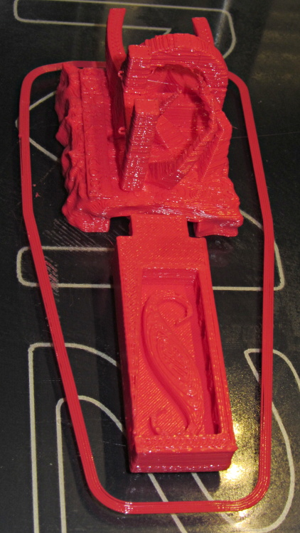
    The top view shows the shape in the box looks fine, but with some curls in the main structure. The arch closed over a few random strands, so it’s rougher than I’d like:

    M2 - 3DHacker object - top
    M2 – 3DHacker object – top

    The spires are lumpy and there’s more striation than I’d like, but this lies well outside the realm of stuff that I build. If I were doing it for real, I’d add some support structures here & there.

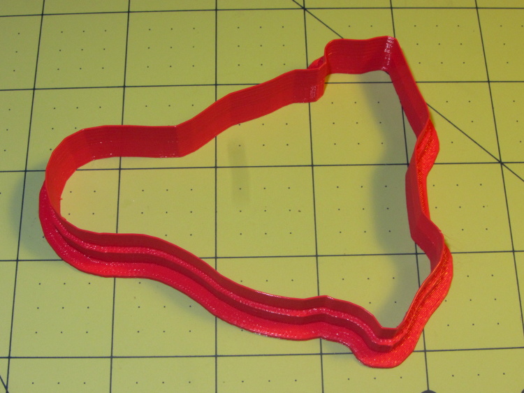
    A new Tux Cookie Cutter is perfect:

    Tux cutter - M2 single-wall blade - overview
    Tux cutter – M2 single-wall blade – overview

    The wall stacks up neatly to the single-thread blade on the top, with none of the retraction glitches found in the Thing-O-Matic version:

    Tux cutter - M2 single-wall blade - side view
    Tux cutter – M2 single-wall blade – side view

    So, all in all, I’d say there’s not much room for improvement.

    Now, to coerce LinuxCNC into producing similar results on the same hardware, then proceed onward from there…

  • Makergear M2: CNC Platform Corner Clips

    The CNC version of the corner clips looks much better than the prototypes:

    M2 glass retaining clip
    M2 glass retaining clip

    Tightening the screws until the clip just flattens puts enough force on the glass + heat spreader stack to hold it firmly against the balls in the bottom pad. The solid rubber L-shaped bumpers and screws hold the glass in position against XY forces… and the whole affair looks much better than the original (and perfectly serviceable) bulldog clips. These clips free up the entire surface of the glass plate, minus four 12 mm triangles that you could, if you were desperate, print right over.

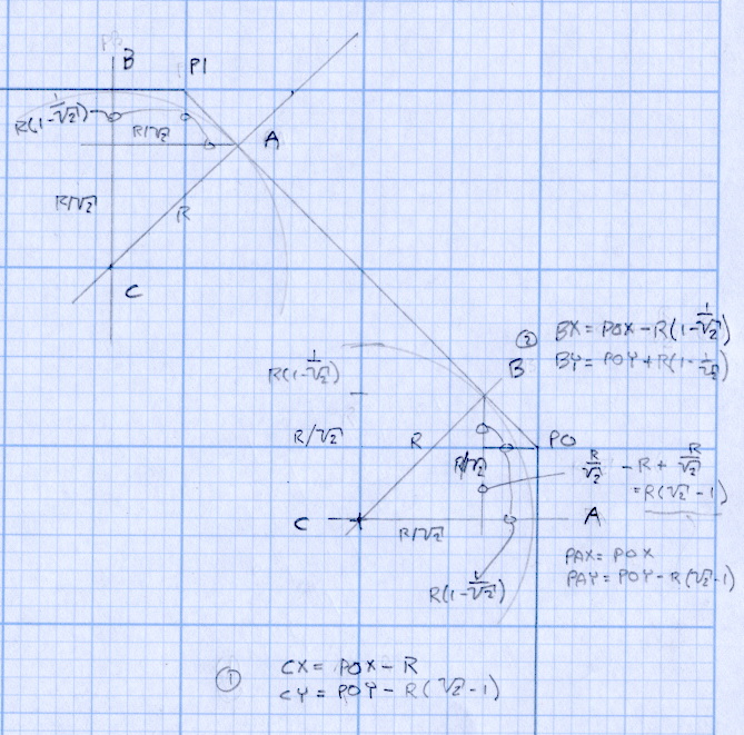
    Although it’d be easier to just hack out an angular clip, I wrote a bit of G-Code to put a nice radius on each corner. The clip sits atop the rubber bumper with a 0.5 mm margin to keep the metal edges away from fingers; they’re smooth, but it’s still a strip of 6 mil (= 0.15 mm) phosphor bronze and feels a lot like a knife edge if you press hard enough.

    The radius on the three outside corners is a special-case solution of the general circle-through-three-points problem, taking advantage of the symmetry and right-triangle-ness of the corners. This sketch shows the details:

    M2 Platform Clip Doodles 4 - corner fairing with margin
    M2 Platform Clip Doodles 4 – corner fairing with margin

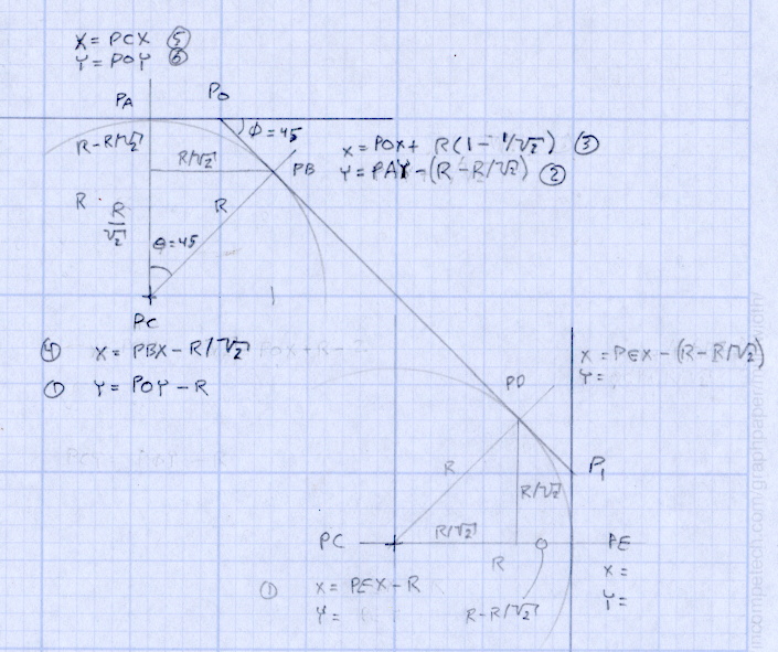
    The two corners on the bevel over the glass plate have a fixed radius. I reworked my original fairing arc solution for outside cutting and doodled it up for this situation:

    M2 Platform Clip Doodles 5 - bevel full solution
    M2 Platform Clip Doodles 5 – bevel full solution

    The outside corner radius worked out to 5 mm and I set the bevel radius at 3 mm. I think the latter made those corners a bit too sharp, but it’s Good Enough for my simple needs.

    Drilling and machining the clips required a fixture:

    M2 platform clips - milling edges
    M2 platform clips – milling edges

    That’s a story for another day.

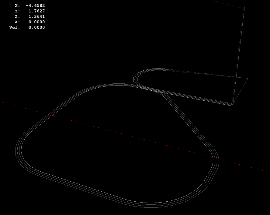
    I used cutter diameter compensation to mill the edges, starting oversize by 1.5 mm and working downward by 0.5 mm on each pass to the actual diameter. That gradually trimmed off the edges without any excitement, so I could start with rough-trimmed stock and not worry about precision hand trimming.

    I thought climb milling (CW around the part) would produce better results, but it tended to smear the phosphor bronze against the fixture:

    M2 Corner Clips - Climb milling tool paths
    M2 Corner Clips – Climb milling tool paths

    Conventional milling (CCW around the part) actually worked, but it required fancier entry and exit moves:

    M2 Corner Clips - Conventional milling tool paths
    M2 Corner Clips – Conventional milling tool paths

    This part is the kind and size of machining perfectly suited to a Sherline CNC mill…

    The LinuxCNC G-Code source:

    ( M2 Build Platform Corner Clips )
    ( Ed Nisley - KE4ZNU - July 2013 )
    ( Fixture origin at right-front corner pip )
    
    ( Flow Control )
    #<_Do_Drill> = 0		( Drill two holes in clip )
    #<_Do_Mill> = 1			( Mill clip outline )
    #<_Climb_Mill> = 0		( 0 = conventional 1 = climb)
    
    ( Fixture info )
    #<_Drill_X_Fixture> = 5.0	( Drill station origin )
    #<_Drill_Y_Fixture> = 5.0
    
    #<_Drill_Num> = 30			( Drill number in tool table)
    #<_Drill_Retract> = 15
    #<_Drill_Depth> = -1.0
    #<_Drill_Feed> = 300
    #<_Drill_Speed> = 3000
    
    #<_Mill_X_Fixture> = 40.0	( Mill station origin )
    #<_Mill_Y_Fixture> = 5.0
    
    #<_Mill_Num> = 3			( Mill number in tool table)
    #<_Mill_Dia> = 4.60			( actual tool diameter)
    #<_Mill_Dia_Incr> = 0.50
    #<_Mill_Dia_Steps> = 3
    #<_Mill_Retract> = 15
    #<_Mill_Depth> = -0.5
    #<_Mill_Feed> = 300
    #<_Mill_Speed> = 8000
    
    (----------------)
    
    (  Initialize first tool length at probe switch )
    (     Assumes G59.3 is still in machine units, returns in G54 )
    (  ** Must set these constants to match G20 / G21 condition! )
    
    #<_Probe_Speed>     = 400            ( set for something sensible in mm or inch )
    #<_Probe_Retract>   =   1            ( ditto )
    
    O<Probe_Tool> SUB
    
    G49                     ( clear tool length compensation )
    G30                     ( move above probe switch )
    G59.3                   ( coord system 9 )
    
    G38.2 Z0 F#<_Probe_Speed>           ( trip switch on the way down )
    G0 Z[#5063 + #<_Probe_Retract>]     ( back off the switch )
    G38.2 Z0 F[#<_Probe_Speed> / 10]    ( trip switch slowly )
    
    #<_ToolZ> = #5063                    ( save new tool length )
    
    G43.1 Z[#<_ToolZ> - #<_ToolRefZ>]    ( set new length )
    
    G54                     ( coord system 0 )
    G30                     ( return to safe level )
    
    O<Probe_Tool> ENDSUB
    
    (-------------------)
    (-- Initialize first tool length at probe switch )
    
    O<Probe_Init> SUB
    
    #<_ToolRefZ> = 0.0      ( set up for first call )
    
    O<Probe_Tool> CALL
    
    #<_ToolRefZ> = #5063    ( save trip point )
    
    G43.1 Z0                ( tool entered at Z=0, so set it there )
    
    O<Probe_Init> ENDSUB
    
    (-------------------)
    (-- Mill one pass around outline with tool diameter passed in #1 )
    
    O<MillOutline> SUB
    
    #<X_Size> = 22.0		( size of support spider pad = nominal clip size )
    #<Y_Size> = 22.0
    #<Base_Bevel> = 3.2		( X or Y length of corners clipped from spider pad )
    
    #<Bevel_Size> = 9.0		( remaining part of trimmed edges on clip )
    #<Bevel_Radius> = 3.0	( fairing radius at bevel corners on clip)
    
    #<R_Div_Root2> = [#<Bevel_Radius> / SQRT[2]]
    #<R_1M_Recip_R2> = [#<Bevel_Radius> * [1 - 1/SQRT[2]]]
    #<R_Root2_M1> = [#<Bevel_Radius> * [SQRT[2] - 1]]
    
    #<Margin> = 0.5			( recess inside of nominal )
    
    #<X_Min> = [#<Margin>]
    #<X_Max> = [#<X_Size> - #<Margin>]
    
    #<Y_Min> = [#<Margin>]
    #<Y_Max> = [#<Y_Size> - #<Margin>]
    
    #<Corner_Rad> = [[#<Margin> * [1 - SQRT[2]] + [#<Base_Bevel> / SQRT[2]]] / [SQRT[2] - 1]]
    
    O<Climb> IF [#<_Climb_Mill>]
    
    G0 X#<X_Min> Y[#<Y_Max> + 3*#<_Mill_Dia>]
    G1 Z#<_Mill_Depth> F#<_Mill_Feed>
    
    G41.1 D#1
    
    G3 X[#<X_Min>] Y#<Y_Max> I0 J[0-1.5*#<_Mill_Dia>]	( cutter comp on: entry move)
    
    G1 X[#<Bevel_Size> - #<R_Root2_M1>]
    G2 X[#<Bevel_Size> + #<R_1M_Recip_R2>] Y[#<Y_Max> - #<R_1M_Recip_R2>] J[0-#<Bevel_Radius>]
    
    G1 X[#<X_Max> - #<R_1M_Recip_R2>] Y[#<Bevel_Size> + #<R_1M_Recip_R2>]
    G2 X#<X_Max> Y[#<Bevel_Size> - #<R_Root2_M1>] I[0-#<R_Div_Root2>] J[0-#<R_Div_Root2>]
    
    G1 Y[#<Y_Min> + #<Corner_Rad>]
    G2 X[#<X_Max> - #<Corner_Rad>] Y#<Y_Min> I[0-#<Corner_Rad>] J0
    
    G1 X[#<X_Min> + #<Corner_Rad>]
    G2 X#<X_Min> Y[#<Y_Min> + #<Corner_Rad>] I0 J#<Corner_Rad>
    
    G1 Y[#<Y_Max> - #<Corner_Rad>]
    G2 X[#<X_Min> + #<Corner_Rad>] Y#<Y_Max> I#<Corner_Rad> J0
    
    G40
    
    G0 X#<X_Min> Y[#<Y_Max> + 3*#<_Mill_Dia>]
    (G3 X#<Bevel_Size> Y[#<Y_Max> + 3*#<_Mill_Dia>] I0 J[1.5*#<_Mill_Dia>])	( cutter comp off: safe exit)
    
    G0 X#<X_Min>			( return to start)
    
    O<Climb> ELSE
    
    G0 X#<X_Size> Y[#<Y_Size> + #1/2]
    
    G1 Z#<_Mill_Depth> F#<_Mill_Feed>
    
    G42.1 D#1
    
    G1 X#<Bevel_Size> Y[#<Y_Max>]	( cutter comp on: entry move)
    
    G1 X[#<X_Min> + #<Corner_Rad>]
    G3 X#<X_Min> Y[#<Y_Max> - #<Corner_Rad>] I0 J[0-#<Corner_Rad>]
    
    G1 Y[#<Y_Min> + #<Corner_Rad>]
    G3 X[#<X_Min> + #<Corner_Rad>] Y[#<Y_Min>] I#<Corner_Rad> J0
    
    G1 X[#<X_Max> - #<Corner_Rad>]
    G3 X[#<X_Max>] Y[#<Y_Min> + #<Corner_Rad>] I0 J#<Corner_Rad>
    
    G1 Y[#<Bevel_Size> - #<R_Root2_M1>]
    G3 X[#<X_Max> - #<R_1M_Recip_R2>] Y[#<Bevel_Size> + #<R_1M_Recip_R2>] I[-#<Bevel_Radius>]
    
    G1 X[#<Bevel_Size> + #<R_1M_Recip_R2>] Y[#<Y_Max> - #<R_1M_Recip_R2>]
    G3 X[#<Bevel_Size> - #<R_Root2_M1>] Y#<Y_Max> I[-#<R_Div_Root2>] J[-#<R_Div_Root2>]
    
    G2 Y[#<Y_Max> + 3*#<_Mill_Dia>] J[#<_Mill_Dia>*1.5]		( get away from corner)
    G40
    
    G0 X#<X_Size>					( cutter comp off: safe exit)
    G0 Y[#<Y_Size> + #1/2]			( return to start)
    
    O<Climb> ENDIF
    
    O<MillOutline> ENDSUB
    
    (----------------)
    ( Start machining... )
    
    G17 G40 G49 G54 G80 G90 G94 G99	( reset many things )
    
    G21								( metric! )
    G91.1 							( incremental arc centers)
    
    (msg,Verify: G30.1 position in G54 above tool change switch? )
    M0
    (msg,Verify: fixture origin XY touched off? )
    M0
    (msg,Verify: Current tool Z=0 touched off? )
    M0
    
    ( Set up probing)
    O<Probe_Init> CALL
    T0 M6
    
    (---- Drill holes)
    
    O<DoDrill> IF [#<_Do_Drill>]
    
    (debug,Insert drill tool = #<_Drill_Num>)
    T#<_Drill_Num> M6
    O<Probe_Tool> CALL
    (debug,Set spindle to #<_Drill_Speed> rpm )
    M0
    
    G0 X#<_Drill_X_Fixture> Y#<_Drill_Y_Fixture>
    G0 Z#<_Drill_Retract>
    
    G10 L20 P2 X0 Y0 Z#<_Drill_Retract>	( P2 = G55)
    G55					( drill station coordinates )
    
    G81 X5.0 Y15.0 Z#<_Drill_Depth> R#<_Drill_Retract> F#<_Drill_Feed>
    
    G81 X15.0 Y5.0
    
    G54
    
    O<DoDrill> ENDIF
    
    (---- Mill outline )
    ( Start with large diameter and end with actual diameter to trim in stages)
    
    O<DoMill> IF [#<_Do_Mill>]
    
    (debug,Insert mill tool = #<_Mill_Num>)
    T#<_Mill_Num> M6
    O<Probe_Tool> CALL
    (debug,Set spindle to #<_Mill_Speed> rpm )
    M0
    
    G0 X#<_Mill_X_Fixture> Y#<_Mill_Y_Fixture>
    G0 Z#<_Mill_Retract>
    
    G10 L20 P2 X0 Y0 Z#<_Mill_Retract>	( P2 = G55)
    G55					( mill station coordinates )
    
    #<PassCount> = 0
    
    O<MillLoop> DO
    #<Diameter> = [#<_Mill_Dia> + [#<_Mill_Dia_Steps> - #<PassCount>]*#<_Mill_Dia_Incr>]
    
    O<MillOutline> CALL [#<Diameter>]
    
    #<PassCount> = [#<PassCount> + 1]
    O<MillLoop> WHILE [#<PassCount> LE #<_Mill_Dia_Steps>]
    
    ( Finishing pass with zero cut )
    O<MillOutline> CALL [#<Diameter>]
    
    G0 Z#<_Mill_Retract>
    G54
    
    O<DoMill> ENDIF
    
    G30
    
    (msg,Done!)
    M2
    

    The rest of the doodles, which don’t match up with the final G-Code because they represent the earliest versions of the layout:

    M2 Platform Clip Doodles 1 - overall layout
    M2 Platform Clip Doodles 1 – overall layout
    M2 Platform Clip Doodles 2 - bevel
    M2 Platform Clip Doodles 2 – bevel
    M2 Platform Clip Doodles 3 - corner fairing without margin
    M2 Platform Clip Doodles 3 – corner fairing without margin
  • Makergear M2: Prototype Corner Clips

    In the course of normal events around here, the M2 gets tipped to one side or the other. Every time that happens, I rediscover the blindingly obvious fact that there’s nothing holding the glass build plate and the heater to the support spider:

    M2 build platform corner
    M2 build platform corner

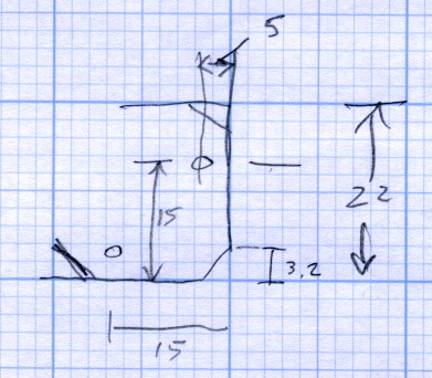
    A few minutes with a metric ruler produced some useful dimensions for the ends of the spider’s arms:

    M2 Platform Support Spider Pad Dimensions
    M2 Platform Support Spider Pad Dimensions

    The Big Box o’ Foamy Things emitted a mouse pad (remember mouse pads?) of exactly the right thickness to bring the corner pads just barely above the level of the glass plate, thus allowing for slight compression:

    M2 corner bumpers
    M2 corner bumpers

    That’s a 1/8 inch hole punch, which is close enough to the M3 screw diameter in foam rubber. It worked fine for the balls in the corner support pads, too.

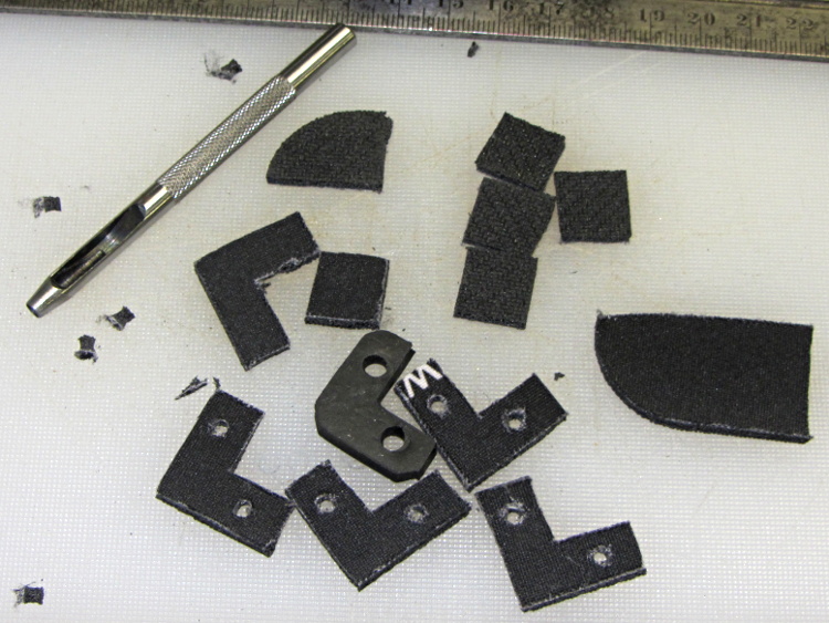
    The long-suffering shop scissors produced results about as pretty as one might expect:

    img_3157 - M2 platform retaining clips - raw cut
    img_3157 – M2 platform retaining clips – raw cut

    Which is to say, not very.

    The material is 6 mil (about 0.15 mm) phosphor bronze, nice and springy. Combined with ripply edges and sharp corners, you get perfectly serviceable serrated knife blades suitable for use in traditional shop ceremonies of ritual scarification of the fingertips.

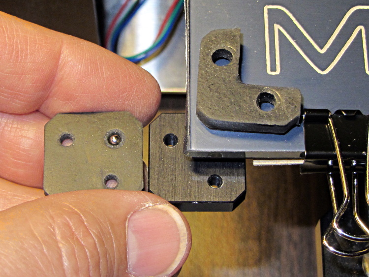
    I stacked the slips, clamped them to the Sherline’s table between sacrificial plastic sheets, used manual CNC to poke a pair of #31 holes (0.120 inch, about the right clearance for M3 screws) at the right spots, and then stacked everything up on the M2:

    M2 platform retaining clip oops - in place
    M2 platform retaining clip oops – in place

    The alert reader will notice a third #31 hole at the wrong spot, which was the first one I drilled and partially explains the lack of pictures of the operation.

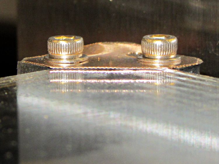
    Sighting across the platform shows that the clip doesn’t lie quite flat on the glass, due to the scissors-cut bending:

    M2 platform retaining clip - edge view
    M2 platform retaining clip – edge view

    However, four of these clips hold the glass firmly to the heat spreader and eliminate the need for the stock bulldog clips, which is what I wanted to find out.

    But they’re ugly and I don’t want to explain that extra hole…

  • Makergear M2: Platform Support Balls

    After adding the insulation below the M2’s build platform heater, I punched a hole in each of the support pads and inserted a 1/8 inch bearing ball:

    M2 HBP support balls
    M2 HBP support balls

    The pads measure just slightly less than 1/8 inch thick, so the balls support the aluminum heat spreader plate. Unlike the pads, the balls hold the plate at a constant distance from the spider which shouldn’t vary with mechanical load.

    As nearly as I can tell, generic rubber expands by maybe 100 parts per million per degree C, so a 3 mm slab might expand by all of 0.02 mm over a 70 °C range: temperature obviously doesn’t make much difference. However, I’m about to add some hold-down clamps to keep the glass plate firmly in place and that pressure might squish the pads.

    Obviously, putting a steel ball between two aluminum plates isn’t something you’d do in a high-stress machine, but the balls must support only the platform and won’t get any shock loading: any shock strong enough to indent the aluminum will probably shatter the glass. I’m pretty sure there won’t be enough motion in the XY plane to produce any wear, either.

    Four points do not define a plane, but the spider and the spreader seem close enough to being planar that all four balls make firm contact. The M2 really does have a good mechanical foundation!


  • Makergear M2: Platform Lighting

    Adding a strip of white LEDs under the X stage helps shed some light on events atop the M2’s build platform; this was very nearly the first improvement after getting the printer, but somehow I’ve never written down where that nice white glow comes from.

    This view shows the strip from below, looking up from the -Y direction in front of the stage:

    White LED strip under X axis frame
    White LED strip under X axis frame

    I originally screwed the wires into the terminals from the hulking 12 V Dell laptop brick for the platform heater, but then I had to unscrew the wires whenever I moved the M2 and I didn’t like sharing the connectors with those huge conductors. Now the LEDs are in parallel with the extruder fan (which runs continuously), sharing the FAN1 screw terminals inside the electronics case.

    The M2 firmware uses PWM to cut the 19.5 V supply from a much smaller laptop brick down to roughly 12 V RMS for the fans, but that isn’t such a Good Thing for LEDs. The strip has 120 Ω resistors that drop about 2.4 V at 20 mA from a 12 V supply, leaving 9.6 V for the LEDs (at about 3.2 V each). Running from 19.5 V means the resistors will see about 9.5 V and pass nearly 80 mA, four times the nominal rating, during each PWM pulse.

    Based on those measurements, the light output doesn’t go up by nearly a factor of four during each pulse.

    I plan to add a 12 V supply to the LinuxCNC box, probably by recycling the 12 V brick from the M2, which will get the LED current back down to a reasonable level. With any luck, they’ll survive this mistreatment and not carry a grudge.

    You could, of course, just power the LEDs from a separate 12 V wall wart, but that adds Yet Another Thing when I carry the M2 to demos.