I’m planning to put all the stepper driver bricks, solid state relays, power suppliers, miscellaneous doodads, and suchlike that will interface LinuxCNC with the M2 printer into a repurposed Dell desktop PC case.
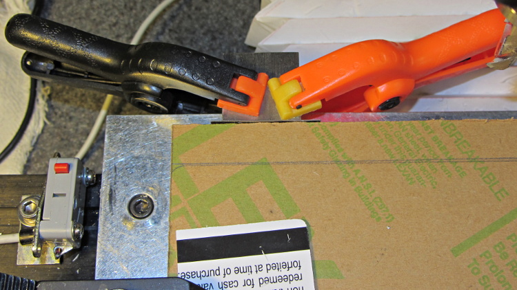
The front of the case had some tabs sticking out that anchored / aligned / captured various bits of hardware; grabbing them with a Vise-Grip, wiggling until the steel failed, and then filing the raw edge solved that problem:

The PC had room for a diskette drive, with a lip protruding below the opening:

A welding pliers wiggled nearly the entire tab at once:

The bulky Dell front panel had four locating pins that mated with four round holes, one of which appears in the first picture. I wanted a somewhat less butt-ugly front than the bare metal grill, but still with some air flow into the case, so I found some 1/4 inch diameter standoffs tapped 4-40 that fit snugly in the holes and cut them to length:

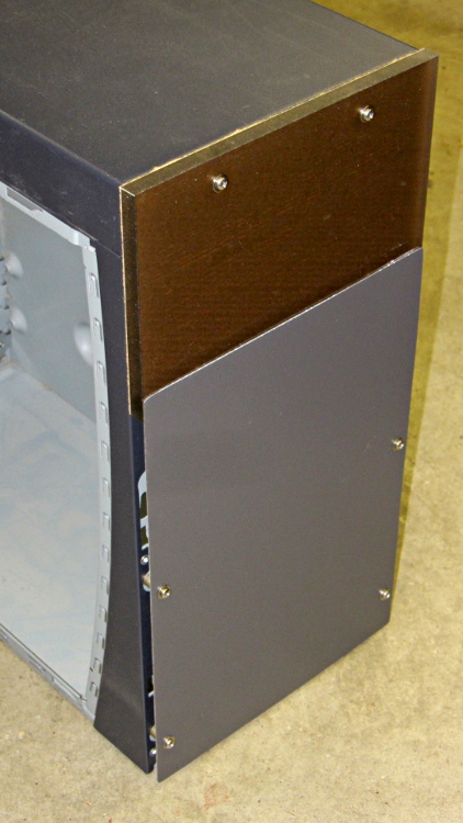
Another defunct Dell case contributed a side panel with roughly the right color. Four match-drilled clearance holes later:

Just for effect, I squared up a slab of nice smoke-brown polycarb to cover the upper opening and perhaps hold das Blinkenlights. The slab was, as almost always happens, slightly too large for the Sherline, so I had to reclamp it to clean up all the sides. It came out about half a millimeter out of square and, being that type of guy, I clamped a block to the back of the table with a suitable spacer against the wide side, removed the spacer, loosened the step clamp on that end, rotated the slab against the block, made another pass, and it came out perfectly square:
Four match-drilled holes and some epoxy later:

I’ll probably put the main AC switch on that top panel, but it looks pretty good even with the protective paper on the back:
I must mill a recess under the vent panel and counterbore the screw heads so everything fits flush and lines up neatly.
Another chunk of aluminum will hold the stepper driver bricks along the front of the case:
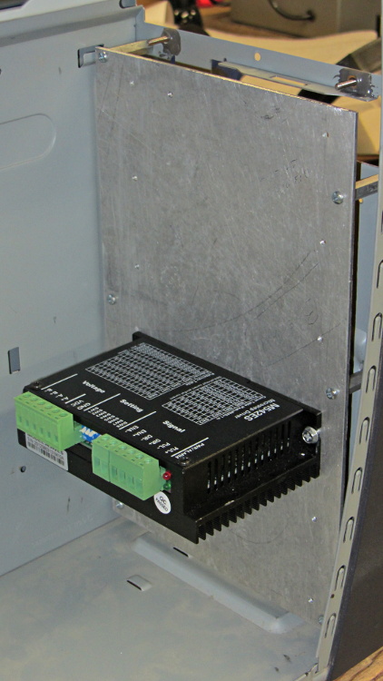
I laid out the holes with a square, eyeballed the spacing on a machinist’s scale, manually punched / drilled / tapped the holes, and it’s all good. The standoffs provide a bit of airflow around the edges; I don’t expect the drivers to get more than slightly warm, because they’re running near the bottom of their current rating. Incidentally, that sheet is a different and much nicer alloy than the pure aluminum I jeweled for the main base plate and will probably not use.
The 24 VDC power supply will mount on the top of the case, up where the Dell PC supply used to reside. The supply has M4 tapped holes and, of course, I don’t have any such standoffs, but I did find some hex standoffs with 6-32 tapped holes on both ends. Bandsaw ’em in half and clean up the raw end to the proper length:
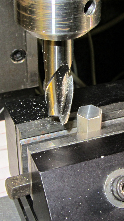
Center drill in the lathe / drill / tap an M4 thread in each one, saw off some M4 screws, slather with red Loctite, insert studs into standoffs, and that should hold the power supply in place with 6-32 screws through the case top:

More Quality Shop Time lies ahead, but it’s coming together…

Comments
7 responses to “LinuxCNC Electronics Case Mods”
I half expected you to turn down the standoffs and single-point cut M4 threads into them. But drilling, tapping, and gluing in studs is a much more reasonable amount of effort.
Sometimes I go overboard, but threading is way skilled-labor-intensive. For standard threads, the Flintstone approach works pretty well.
In retrospect, I should have just drilled clearance holes, buttered the studs with epoxy, and rammed them in place.
A couple of projects in the ever-lengthening queue require camera lens adapter threads, which look like some-metric-pitch-dia x 32 thread/inch. I think I can do that by gimmicking up a low-budget single-point thread mill from a tap and abusing the Sherline, but …
I made a lens mount adapter of sorts by 3D printing barrels slightly undersize to the thread diameter and then carefully using the lens itself to thread into the plastic. For static lens applications, that might be okay? I realize it’s not elegant or proper, but maybe all you need?
That obviously takes a back seat to working, so I’d give it high marks.
Given that I might be using PLA, I bet it’d be possible to do your trick, apply a bit of heat and compression to the outside of the thread, and sort of mash the thread into existence. That’s certainly worth a try; I’ll keep it in mind for when a Round Tuit falls from the sky and rattles that project queue…
Thanks for the tip!
I have a ’93 vintage HP tower (486, 400MB, supposed to be a server, but obsolete before it hit the market, but an OK home-use PC for the era) that’s sitting around. Since it is an HP, it has the usual issues of not-quite compatibility in the power supply and the mo-bo mounts, but it’s a nice chunk of steel and plastic and built like a tank. I’ll give it a while to find a use for it before it gets used for sheet metal stock. I had it running RH 6, but it did better as a space heater than as a computing-machine. Keine blinkenlights. (My favorite set was on the HP2000 mini. We had ours programmed to be a bargraph of the CPU loading.)
[…] other equipment. Although I had high moderate hopes that a boost power supply would convert the 24 V supply I already had for the stepper driver bricks into the 30 V for the heater, it was not to be. So […]
[…] 36 V supply has the same M4 mount points as the 24 V supply, so I cut up another pair of those long 6-32 threaded standoffs to make four mounts. This time, […]