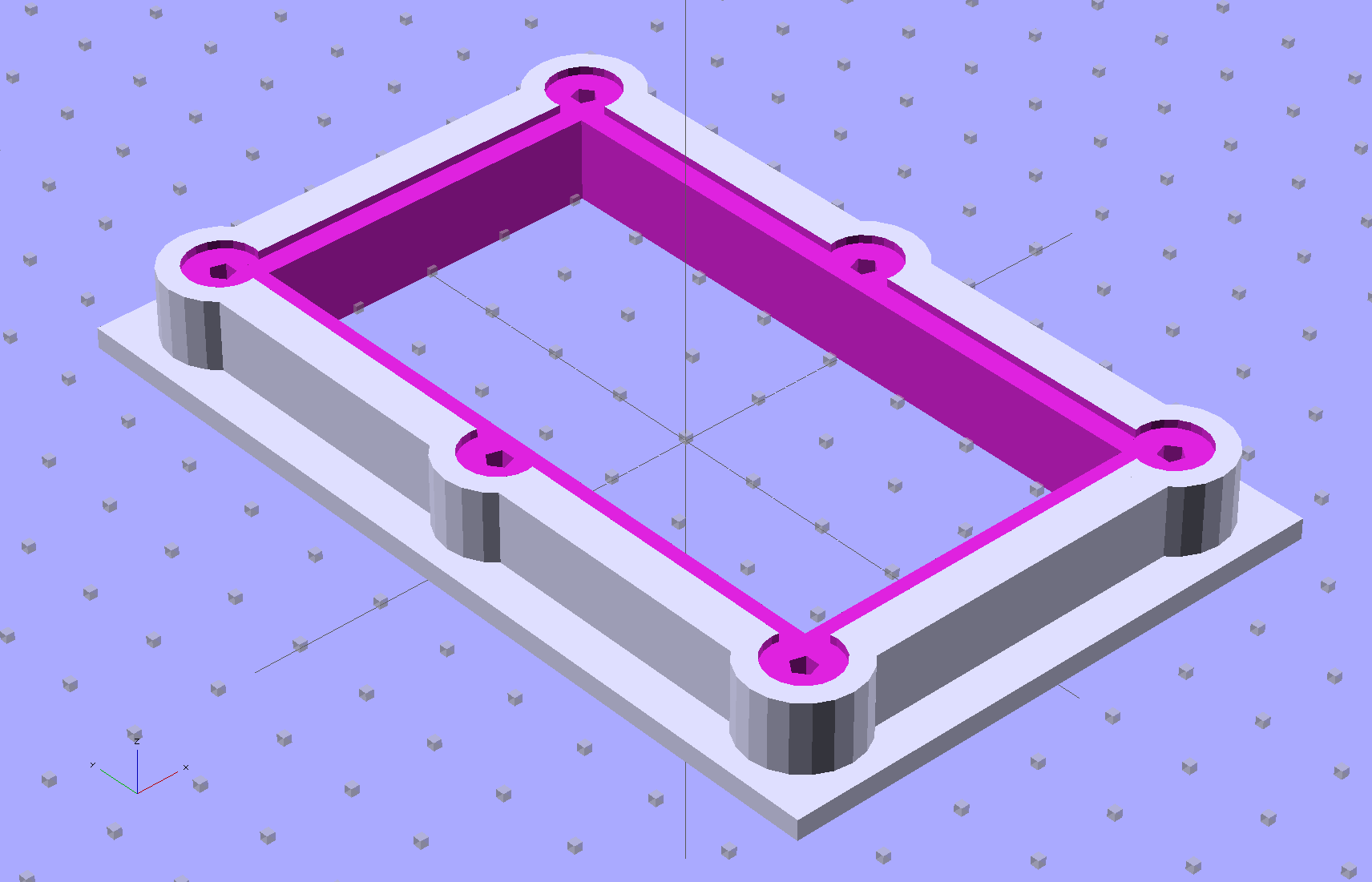
The brassboard PCB for the Hall effect blinky light is too bendy for the SMD parts to survive much debugging, particularly with all the wires hanging off the edges, so I whipped up a stiff mounting bracket that captures the whole thing, with a flange that fits in the work stand arms:
I ran some self-tapping 4-40 hex-head screws into the holes while the plastic was still warm on the M2’s platform:

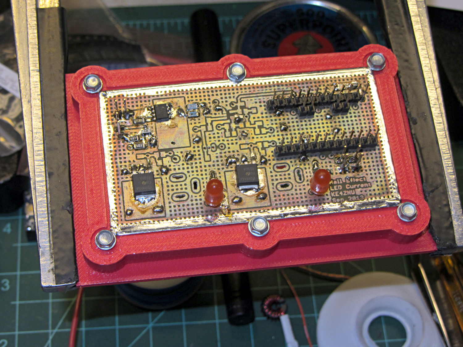
Six screws seem excessive and I’ll probably wind up using just the middle two, but there’s no harm in having more holes and fittings than you really need.
The flange fits neatly into the board holder on the Electronics Workbench, above all the construction clutter:
The nice thing about having a 3D printer: when you need an object like this, a couple of hours later you have one!
The OpenSCAD source code, slightly improved based the results you see above:
// Test support frame for Hall Effect LED Blinky Light
// Ed Nisley KE4ZNU - Sept 2013

ClampFlange = true;

//- Extrusion parameters - must match reality!

ThreadThick = 0.25;
ThreadWidth = 0.40;

function IntegerMultiple(Size,Unit) = Unit * ceil(Size / Unit);

Protrusion = 0.1;

HoleWindage = 0.2;

//- Screw sizes

inch = 25.4;

Tap4_40 = 0.089 * inch;
Clear4_40 = 0.110 * inch;
Head4_40 = 0.211 * inch;
Head4_40Thick = 0.065 * inch;
Nut4_40Dia = 0.228 * inch;
Nut4_40Thick = 0.086 * inch;
Washer4_40OD = 0.270 * inch;
Washer4_40ID = 0.123 * inch;

//- PCB sizes

PCBSize = [46.5,84.0,1.0];
PCBShelf = 2.0;

Clearance = 4*[ThreadWidth,ThreadWidth,0];

WallThick = IntegerMultiple(4.0,ThreadWidth);
FrameHeight = 5.0;

ScrewOffset = 0.0 + Clear4_40/2;

OAHeight = FrameHeight + Clearance[2] + PCBSize[2];

FlangeExtension = 3.0;
FlangeThick = IntegerMultiple(1.5,ThreadThick);
Flange = PCBSize
			+ 2*[ScrewOffset,ScrewOffset,0]
			+ 2*[Washer4_40OD,Washer4_40OD,0]
			+ [2*FlangeExtension,2*FlangeExtension,(FlangeThick - PCBSize[2])]
			;

echo("Flange: ",Flange);
NumSides = 4*5;

//- Adjust hole diameter to make the size come out right

module PolyCyl(Dia,Height,ForceSides=0) {			// based on nophead's polyholes

  Sides = (ForceSides != 0) ? ForceSides : (ceil(Dia) + 2);

  FixDia = Dia / cos(180/Sides);

  cylinder(r=(FixDia + HoleWindage)/2,h=Height,$fn=Sides);
}

//- Put peg grid on build surface

module ShowPegGrid(Space = 10.0,Size = 1.0) {

  RangeX = floor(100 / Space);
  RangeY = floor(125 / Space);

	for (x=[-RangeX:RangeX])
	  for (y=[-RangeY:RangeY])
		translate([x*Space,y*Space,Size/2])
		  %cube(Size,center=true);

}

//- Build it

ShowPegGrid();

difference() {
	union() {									// body block and screw bosses
		translate([0,0,OAHeight/2])
			color("LightBlue")
			cube(PCBSize + Clearance + [2*WallThick,2*WallThick,FrameHeight],center=true);
		for (x=[-1,1], y=[-1,0,1]) {
			translate([x*(PCBSize[0]/2 + ScrewOffset),
						y*(PCBSize[1]/2 + ScrewOffset),
						0])
				color("Orchid") cylinder(r=Washer4_40OD,h=OAHeight,$fn=NumSides);
		}
		if (ClampFlange)
			translate([0,0,Flange[2]/2])
			color("SeaGreen") cube(Flange,center=true);
	}

	for (x=[-1,1], y=[-1,0,1]) {				// screw holes and washer recesses
		translate([x*(PCBSize[0]/2 + ScrewOffset),
					y*(PCBSize[1]/2 + ScrewOffset),
					-Protrusion])
			rotate((x-1)*90)
			PolyCyl(Tap4_40,(OAHeight + 2*Protrusion));
		translate([x*(PCBSize[0]/2 + ScrewOffset),
					y*(PCBSize[1]/2 + ScrewOffset),
					OAHeight - PCBSize[2]])
			PolyCyl(1.2*Washer4_40OD,(PCBSize[2] + Protrusion),NumSides);
	}

	translate([0,0,OAHeight/2])					// through hole below PCB
		cube(PCBSize - 2*[PCBShelf,PCBShelf,0] + [0,0,2*OAHeight],center=true);

	translate([0,0,(OAHeight - (PCBSize[2] + Clearance[2])/2 + Protrusion/2)])	// PCB pocket on top
		cube(PCBSize + Clearance + [0,0,Protrusion],center=true);
}

Comments
2 responses to “3D Printed PCB Stiffening Bracket”
Looks like a fine solution especially for boards without mounting holes. Sometime standoffs get a bit tedious when there are that many (6) and if there is accumulation error from drilling holes by eye it is even more fun. So many tiny boards without mounting holes of any kind are supposed to be mounted on a piece of foam tape I suppose.
This being a test board, I didn’t bother with mounting holes… but that doesn’t begin to explain all the hole-less commercial boards.
Clamping the soldered copper tape around the perimeter with the edge of a screw head worked perfectly!