So, for reasons I need not go into, I needed an OpenSCAD solid model of a custom cookie cutter produced on an Afinia 3D printer from a Trimble Sketchup model:

The cutter is still attached to the raft that, it seems, is required for passable results on the Afinia’s platform.
Having already figured out how to wrap a cutter around a shape, the most straightforward procedure starts by extracting the cutter’s shape. So, lay the cutter face down on the scanner and pull an image into GIMP:

Blow out the contrast to eliminate the background clutter, then posterize to eliminate shadings:

Select the black interior region, grow the selection by a pixel or two, then shrink it back to eliminate (most of) the edge granularity, plunk it into a new image, and fill with black:

Now the magic happens…
Import the bitmap image into Inkscape. In principle, you can auto-trace the bitmap outline and clean it up manually, but a few iterations of that convinced me that it wasn’t worth the effort. Instead, I used Inkscape’s Bézier Curve tool to drop nodes (a.k.a. control points) at all the inflection points around the image, then warped the curves to match the outline:
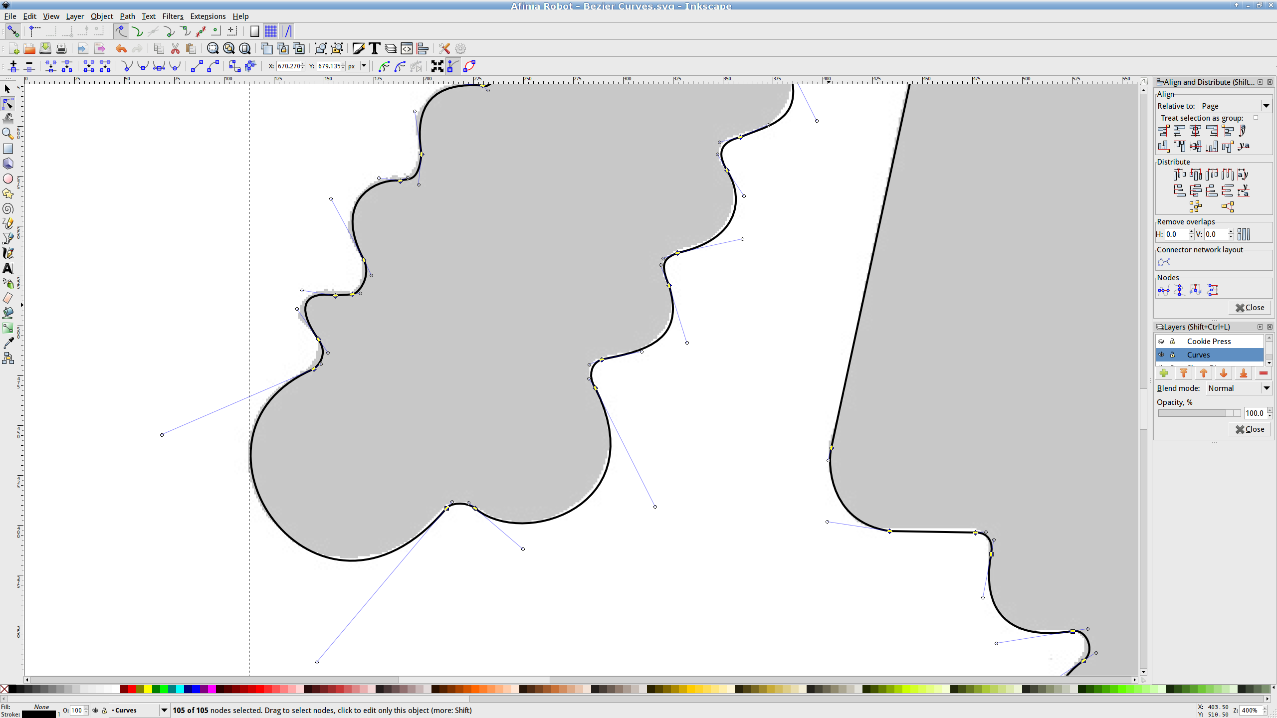
If you’re doing that by hand, you could start with the original scanned image, but the auto-trace function works best with a high-contrast image and, after you give up on auto-tracing, you’ll find it’s easier to hand-trace a high-contrast image.
Anyhow, the end result of all that is a smooth path around the outline of the shape, without all the gritty details of the pixelated version. Save it as an Inkscape SVG file for later reference.
OpenSCAD can import a painfully limited subset of DXF files that, it seems, the most recent versions of Inkscape cannot produce (that formerly helpful tutorial being long out of date). Instead, I exported (using “Save as”) the path from Inkscape to an Encapsulated Postscript file (this is a PNG, as WordPress doesn’t show EPS files):

It’s not clear what the EPS file contains; I think it’s just a list of points around the path that doesn’t include the smooth Bézier goodness. That may account for the grittiness of the next step, wherein the pstoedit utility converts the EPS file into a usable DXF file:
pstoedit dxf:-polyaslines Afinia\ Robot\ -\ Bezier\ Curves.eps Afinia\ Robot\ -\ outline.dxf
Unfortunately, either the EPS file doesn’t have enough points on each curve or pstoedit automatically sets the number of points and doesn’t provide an override: contrary to what you (well, I) might think, the -splineprecision option doesn’t apply to whatever is in the EPS file. In any event, the resulting DXF file has rather low-res curves, but they were good enough for my purposes and OpenSCAD inhaled the DXF and emitted a suitable STL file:

To do that, you set the Layout variable to “Slab”, compile the model, and export the STL.
Being interested only in the process and its results, not actually cutting and baking cookies, I tweaked the OpenSCAD parameters to produce stumpy “cutters”:

You do that by setting the Layout variable to “Build”, compile the model, and export yet another STL. In the past, this seemed to be a less fragile route than directly importing and converting the DXF at each stage, but that may not be relevant these days. In any event, having an STL model of the cookie may be useful in other contexts, so it’s not entirely wasted effort.
Run the STL through Slic3r to get the G-Code as usual.
The resulting model printed in about 20 minutes apiece on the M2:

As it turns out, the fact that the M2 can produce ready-to-use cutters, minus the raft, is a strong selling point.
Given a workable model, the next step was to figure out the smallest possible two-thread-wide cutter blade, then run variations of the Extrusion Factor to see how that affected surface finish. More on that in a while.
The OpenSCAD source isn’t much changed from the original Tux Cutter; the DXF import required different scale factors:
// Robot cookie cutter using Minkowski sum
// Ed Nisley KE4ZNU - Sept 2011
// August 2013 adapted from the Tux Cutter

Layout = "Build";				// Build Slab

//- Extrusion parameters - must match reality!

ThreadThick = 0.25;
ThreadWidth = 0.40;

function IntegerMultiple(Size,Unit) = Unit * ceil(Size / Unit);

MaxSize = 150;				// larger than any possible dimension ...

Protrusion = 0.1;

//- Cookie cutter parameters

Size = 95;

TipHeight = IntegerMultiple(3.0,ThreadThick);
TipThick = 1.5*ThreadWidth;			// 1.5* = thinnest 2-thread wall, 1.0* thread has gaps

WallHeight = IntegerMultiple(1.0,ThreadThick);
WallThick = 4.5*ThreadWidth;

LipHeight = IntegerMultiple(1.0,ThreadWidth);
LipThick = IntegerMultiple(5,ThreadWidth);

//- Wrapper for the shape of your choice

module Shape(Size) {
  Robot(Size);
}

//- A solid slab of Tux goodness in simple STL format
// Choose magic values to:
//		center it in XY
//		reversed across Y axis (prints with handle on bottom)
//		bottom on Z=0
//		make it MaxSize from head to feet

module Tux(Scale) {
  STLscale = 250;
  scale(Scale/STLscale)
	translate([105,-145,0])
	  scale([-1,1,24])
		import(
		  file = "/mnt/bulkdata/Project Files/Thing-O-Matic/Tux Cookie Cutter/Tux Plate.stl",
		  convexity=5);
}

module Robot(Scale) {
    STLscale = 100.0;
    scale(Scale / STLscale)
			scale([-1,1,10])
				import("/mnt/bulkdata/Project Files/Thing-O-Matic/Pinkie/M2 Challenge/Afinia Robot.stl",
					convexity=10);
}

//- Given a Shape(), return enlarged slab of given thickness

module EnlargeSlab(Scale, WallThick, SlabThick) {

	intersection() {
	  translate([0,0,SlabThick/2])
		cube([MaxSize,MaxSize,SlabThick],center=true);
	  minkowski(convexity=5) {
		Shape(Scale);
		cylinder(r=WallThick,h=MaxSize,$fn=16);
	  }
	}

}

//- Put peg grid on build surface

module ShowPegGrid(Space = 10.0,Size = 1.0) {

  RangeX = floor(100 / Space);
  RangeY = floor(125 / Space);

	for (x=[-RangeX:RangeX])
	  for (y=[-RangeY:RangeY])
		translate([x*Space,y*Space,Size/2])
		  %cube(Size,center=true);

}

//- Build it

ShowPegGrid();

if (Layout == "Slab")
	Shape(Size);

if (Layout == "Build")
	difference() {
	union() {
		translate([0,0,(WallHeight + LipHeight - Protrusion)])
		EnlargeSlab(Size,TipThick,TipHeight + Protrusion);
		translate([0,0,(LipHeight - Protrusion)])
		EnlargeSlab(Size,WallThick,(WallHeight + Protrusion));
		EnlargeSlab(Size,LipThick,LipHeight);
	}
	Shape(Size);					// punch out cookie hole
	}

Comments
8 responses to “Creating a Curvelicious Cookie Cutter”
Is there some reason you couldn’t use the Sketchup model as a starting point? Even though, the ability to replicate something from a scan is useful.
As nearly as I can tell, Sketchup is a 2D mesh modeling program pressed into 3D solid modeling that allows you to generate a spectacularly crappy 3D model that combines all the possible problems in one steaming lump of broken STL triangles.
Tried it a few times, watched several other folks have steel-cage death matches with it, then stepped back from the carnage. Maybe it’s better these days, but I’m pretty firmly attached to programmatic model generation with OpenSCAD.
Absent blatant stupidities on my part, OpenSCAD STL files always print perfectly…
I waded through quite a bit of this fight the other night, on my own. I wish I’d read this first. Anyway, I got Inkscape’s autotrace to work surprisingly well as a two-pass solution, first with brightness cutoff to get a solid block, then with edge detection to get a line. That imported into pycam and looked great, and also did fine with gcodetools. My big stumbling block was wanting to get it into FreeCAD because I want to cast it and need to add sprues, which is easier for me with a WYSIWYG… but it appears that inkscape’s autotracer churns out beziers and freecad doesn’t read those. Grumble.
When I unleashed it on the robot pattern, it created a bazillion bezier curves, some spanning all of three pixels. I tried deleting them, but finally realized I’d be better off just creating the necessary ones by hand. Glad to hear it works, though; I’ll give it another chance on something else in a bit…
I’m sure there’s a filter program out there that does exactly what you want, but … more likely, it’s a combination of command-line switches on something else that seems totally unrelated.
Fire the crucible furnace!
I had the bazillion bezier curves thing, but largely on areas where it had a false-detect of a sharp corner, where what it was actually seeing was debris. (Scanning a used exhaust gasket.) I ended up deleting them wholesale, as well; since I have extremely large, gradual curves I can select 20 out of 21 and delete them and still end up with a more than adequate outline. Your situation is significantly more challenging, I think.
Faced with a similar need to trace pictures into cookie cutters I ran across an HTML based editor which allowed you to load a picture, hand trace it and spit it out as Openscad polygons.
http://www.thingiverse.com/thing:14200
Unfortunately the online version appears to be no longer hosted but the source is still there.
That’s a clever gadget!
OpenSCAD’s CGAL back end uses polygon tesselations, so it can’t directly handle Bezier curves. Worse, there seems to be no clean way to convert Bezier curves into something that OpenSCAD can use, with decent control of the curve-to-line resolution. It’s a simple matter of software, but … [sigh]
[…] of the Curvelicious Cookie Cutter effort involved making the thinnest possible cutter blade wall consisting of two adjacent threads, […]