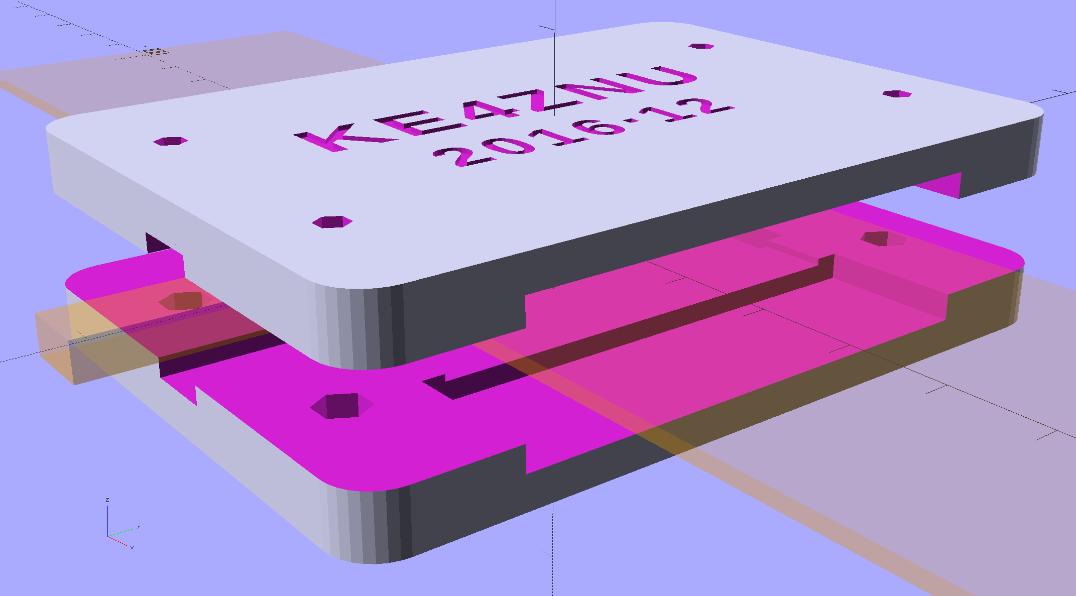
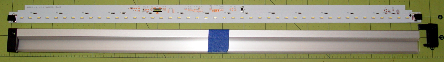
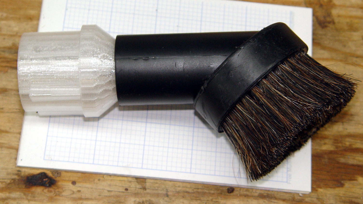
A cleaned up version of my trusty circuit board holder now keeps the 60 kHz preamp off what passes for a floor in the attic:

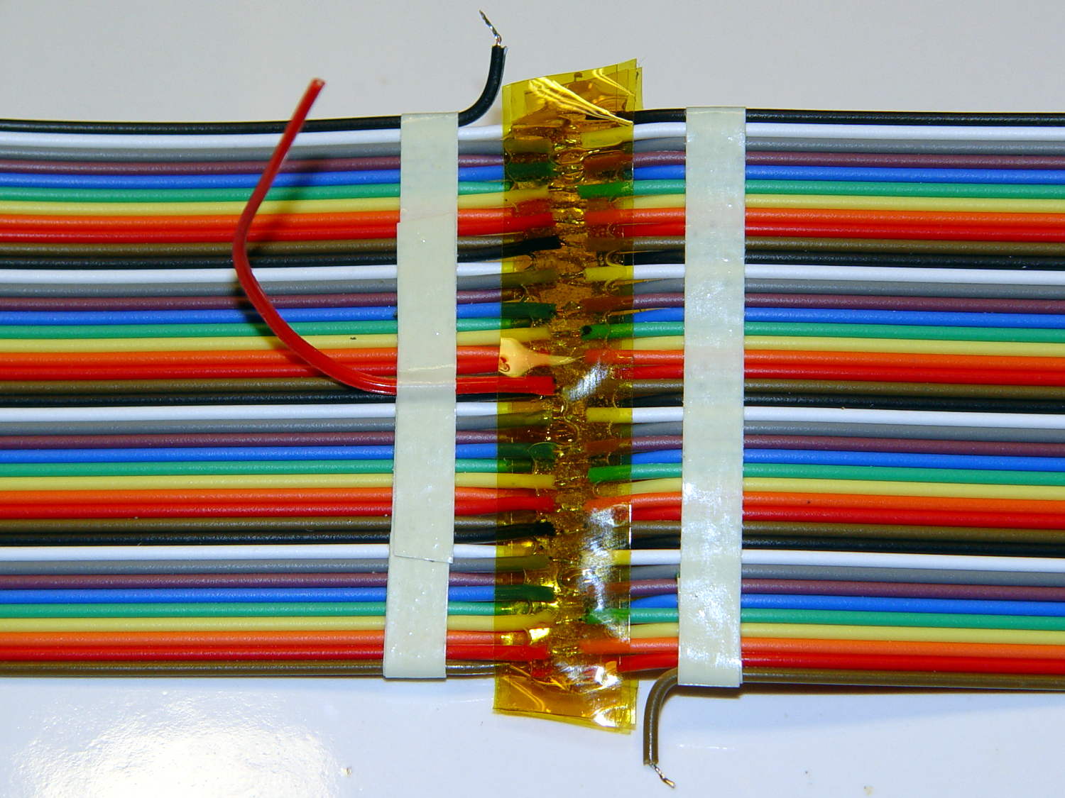
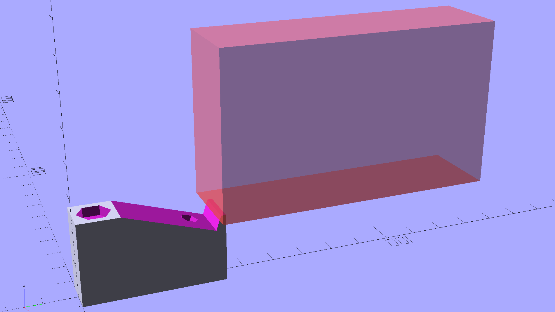
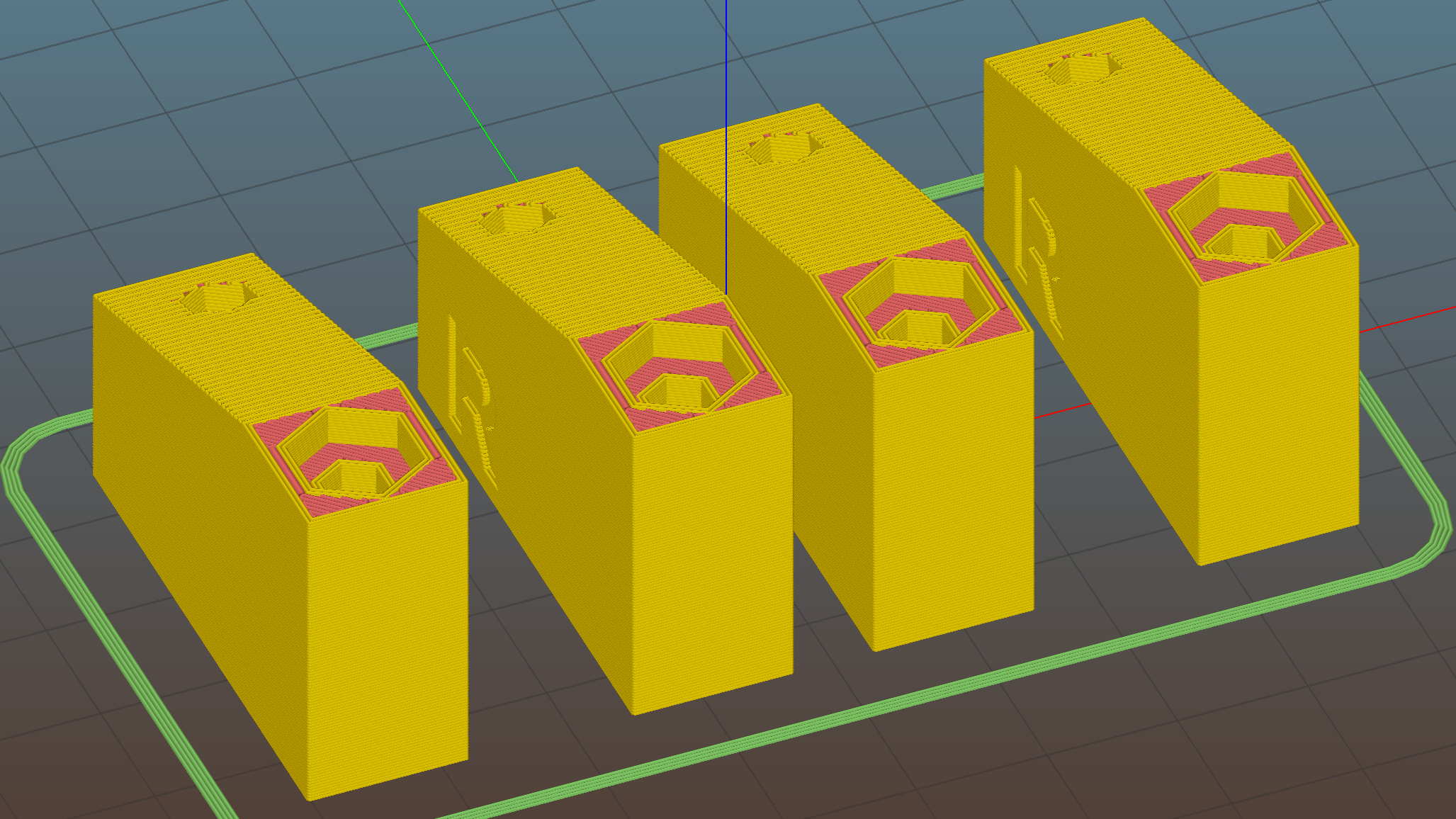
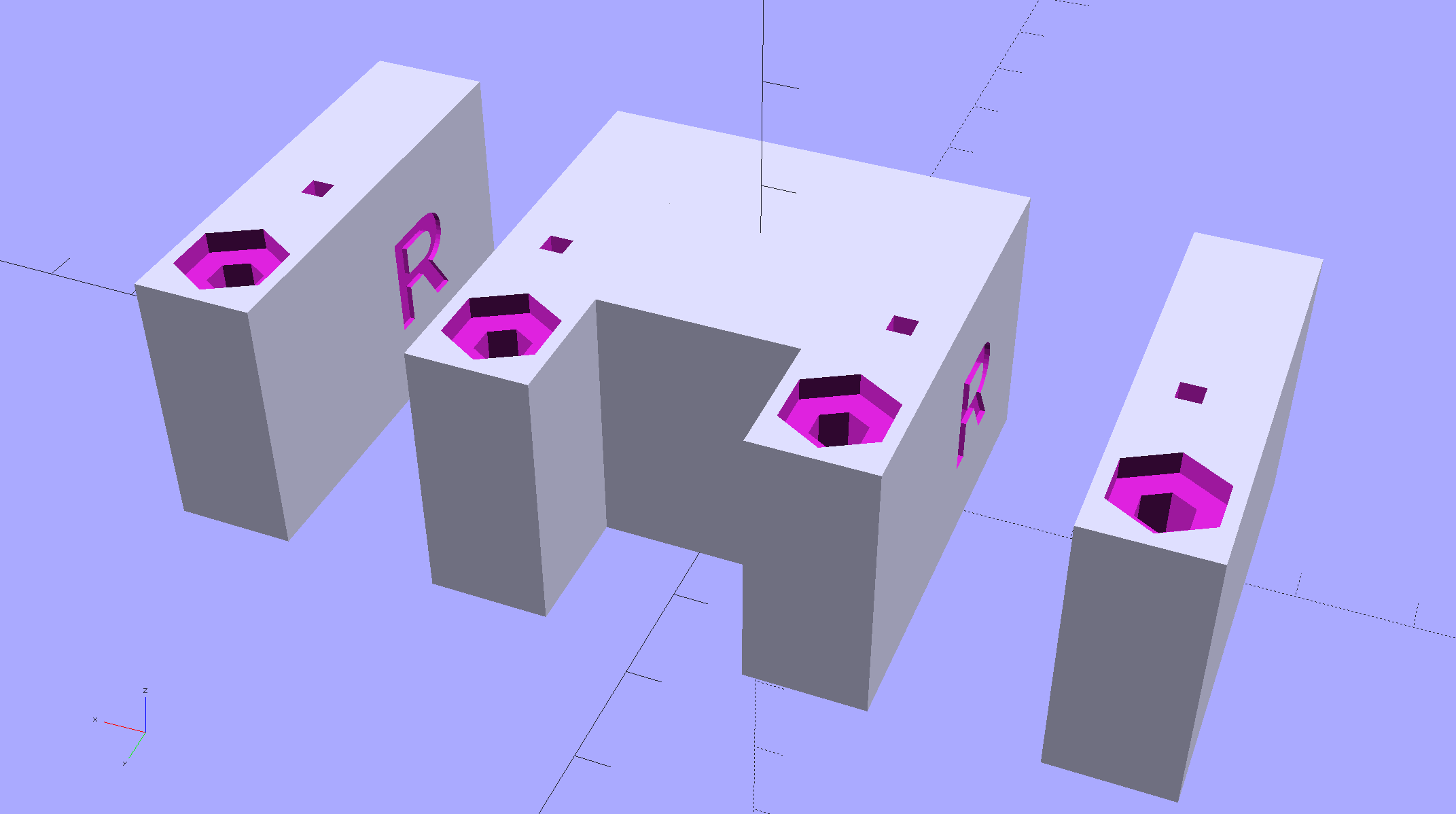
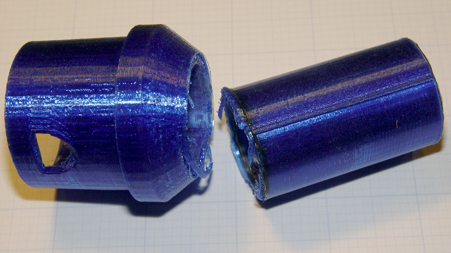
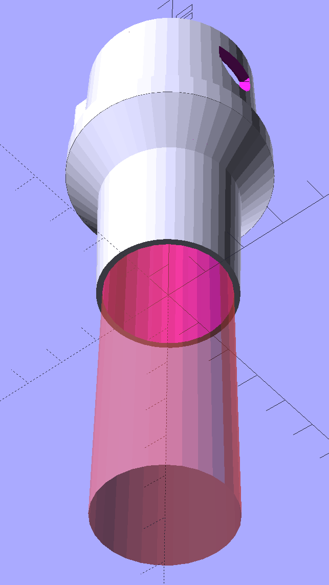
The solid model became slightly taller than before, due to a serious tangle of wiring below the board, with a narrower flange that fits just as well in the benchtop gripper:

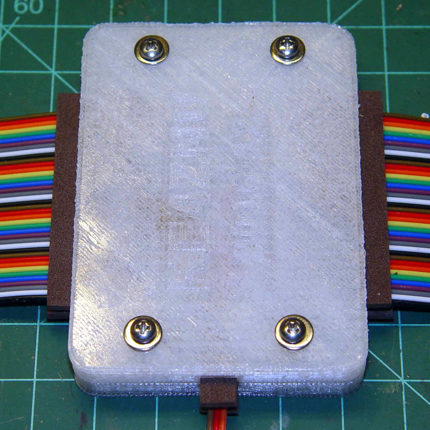
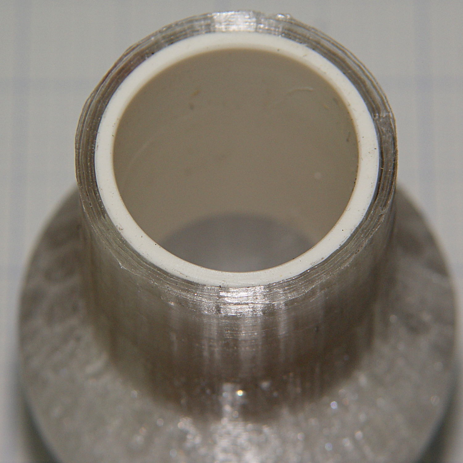
Tidy brass inserts epoxied in the corners replace the previous raw screw holes in the plastic:
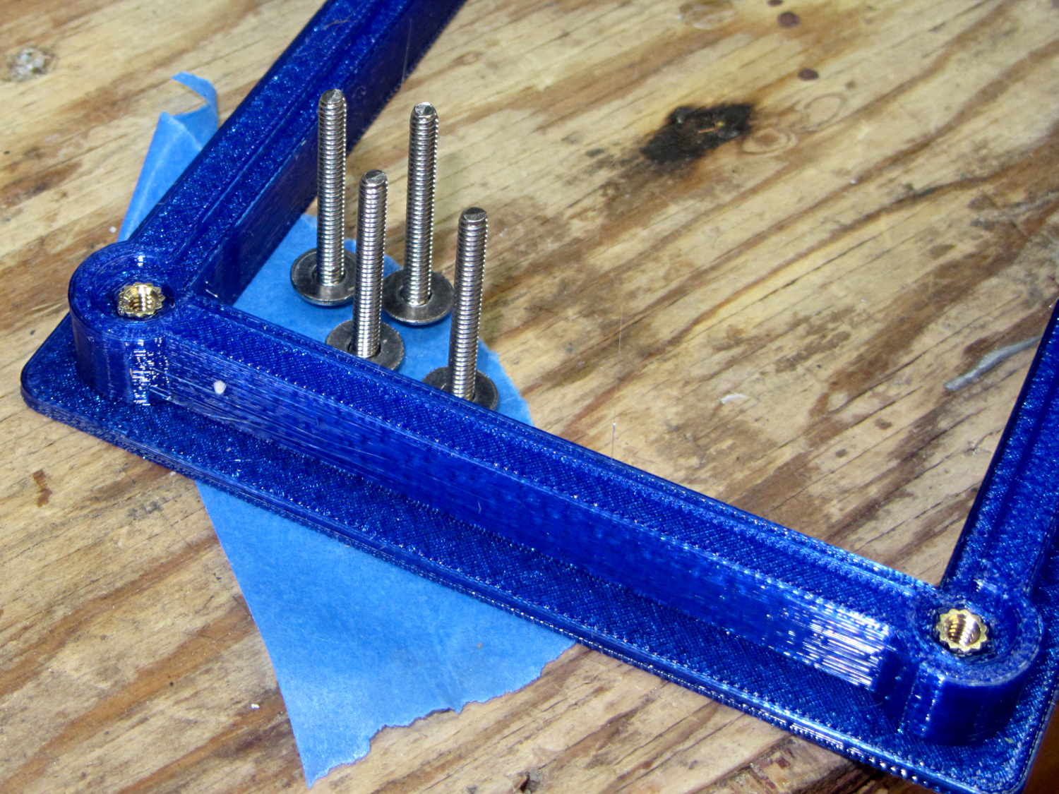
The screws standing on their heads have washers epoxied in place, although that’s certainly not necessary; the dab of left-over epoxy called out for something. The screws got cut down to 7 mm after curing.
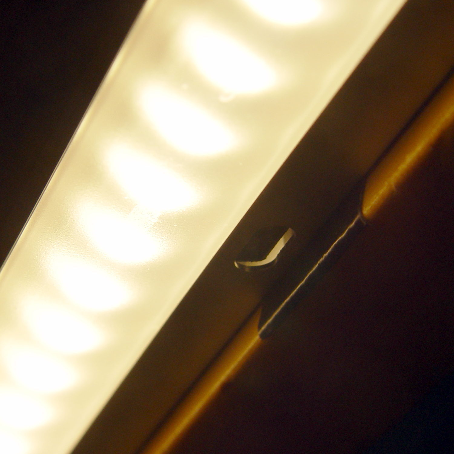
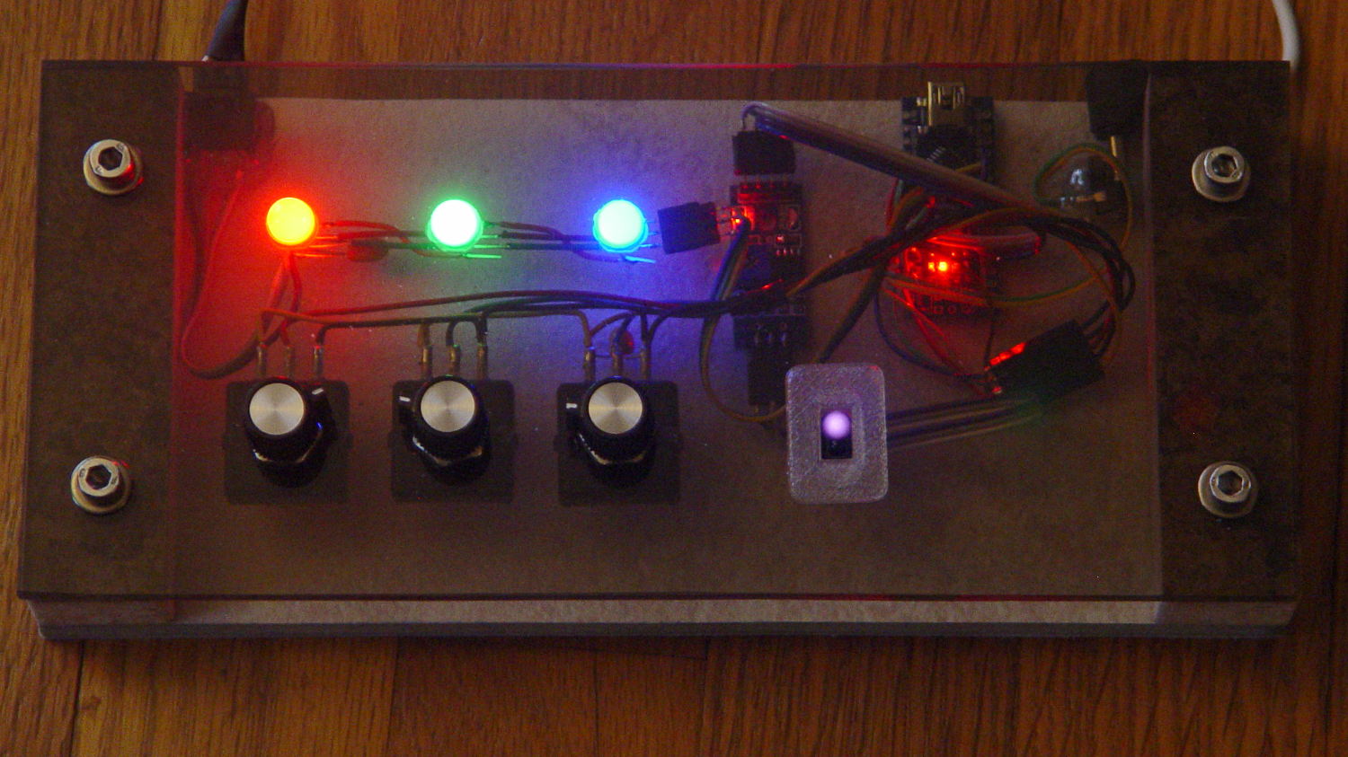
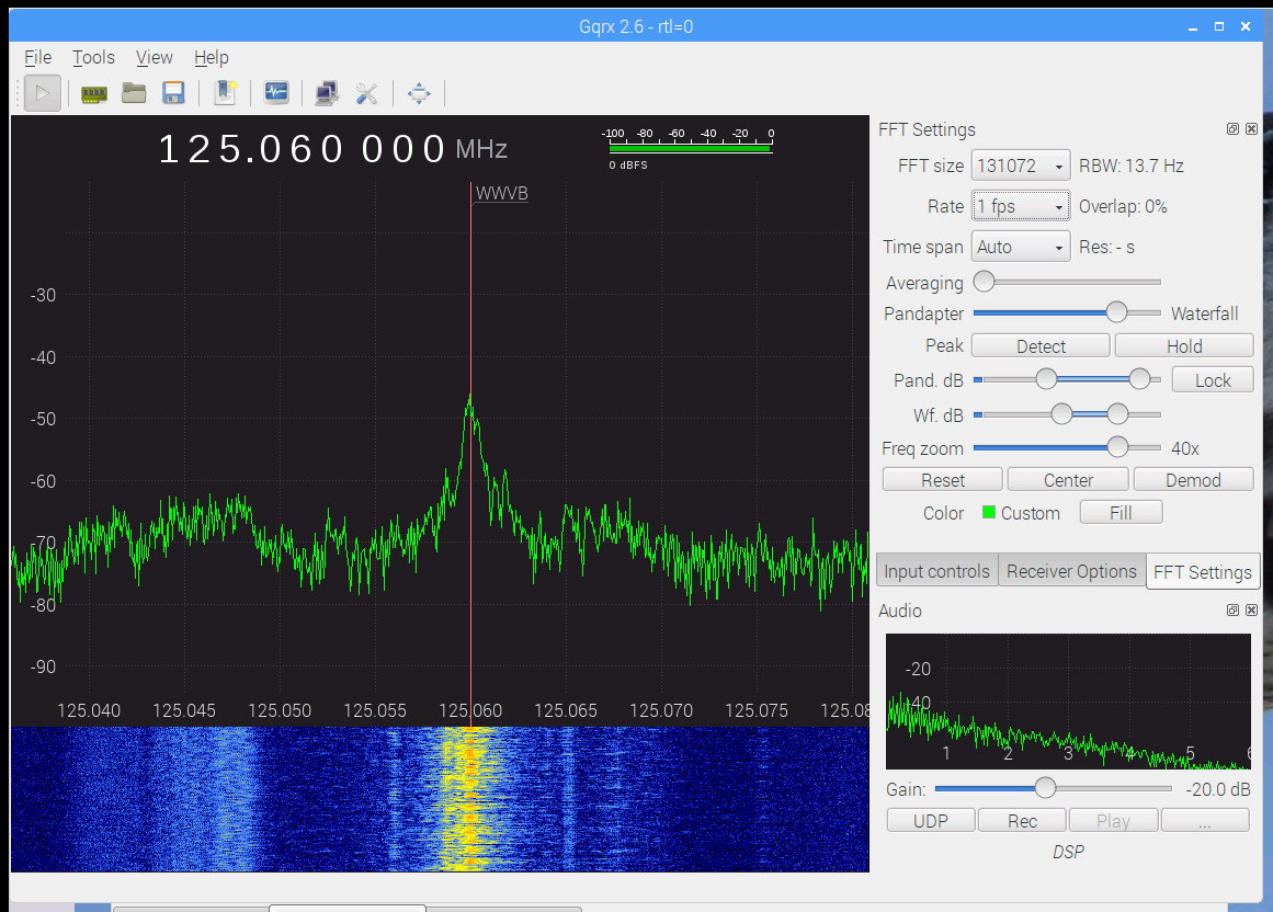
The preamp attaches to a lumpy circle of loop antenna hung from the rafters and returns reasonable results:
The OpenSCAD source code as a GitHub Gist:
This file contains hidden or bidirectional Unicode text that may be interpreted or compiled differently than what appears below. To review, open the file in an editor that reveals hidden Unicode characters.
Learn more about bidirectional Unicode characters
| // Test support frame for proto boards | |
| // Ed Nisley KE4ZNU – Jan 2017 | |
| ClampFlange = true; | |
| Channel = false; | |
| //- Extrusion parameters – must match reality! | |
| ThreadThick = 0.25; | |
| ThreadWidth = 0.40; | |
| function IntegerMultiple(Size,Unit) = Unit * ceil(Size / Unit); | |
| Protrusion = 0.1; | |
| HoleWindage = 0.2; | |
| //- Screw sizes | |
| inch = 25.4; | |
| Tap4_40 = 0.089 * inch; | |
| Clear4_40 = 0.110 * inch; | |
| Head4_40 = 0.211 * inch; | |
| Head4_40Thick = 0.065 * inch; | |
| Nut4_40Dia = 0.228 * inch; | |
| Nut4_40Thick = 0.086 * inch; | |
| Washer4_40OD = 0.270 * inch; | |
| Washer4_40ID = 0.123 * inch; | |
| ID = 0; | |
| OD = 1; | |
| LENGTH = 2; | |
| Insert = [3.9,4.6,5.8]; | |
| //- PCB sizes | |
| PCBSize = [110.0,80.0,1.5]; | |
| PCBShelf = 2.0; | |
| Clearance = 2*[ThreadWidth,ThreadWidth,0]; | |
| WallThick = 5.0; | |
| FrameHeight = 10.0; | |
| ScrewOffset = 0.0 + Clear4_40/2; | |
| ScrewSites = [[-1,1],[-1,1]]; // -1/0/+1 = left/mid/right and bottom/mid/top | |
| OAHeight = FrameHeight + Clearance[2] + PCBSize[2]; | |
| FlangeExtension = 3.0; | |
| FlangeThick = IntegerMultiple(2.0,ThreadThick); | |
| Flange = PCBSize | |
| + 2*[ScrewOffset,ScrewOffset,0] | |
| + 2*[Washer4_40OD,Washer4_40OD,0] | |
| + [2*FlangeExtension,2*FlangeExtension,(FlangeThick – PCBSize[2])] | |
| ; | |
| echo("Flange: ",Flange); | |
| NumSides = 4*5; | |
| WireChannel = [Flange[0],15.0,3.0 + PCBSize[2]]; | |
| WireChannelOffset = [Flange[0]/2,25.0,(FrameHeight + PCBSize[2] – WireChannel[2]/2)]; | |
| //- Adjust hole diameter to make the size come out right | |
| module PolyCyl(Dia,Height,ForceSides=0) { // based on nophead's polyholes | |
| Sides = (ForceSides != 0) ? ForceSides : (ceil(Dia) + 2); | |
| FixDia = Dia / cos(180/Sides); | |
| cylinder(r=(FixDia + HoleWindage)/2,h=Height,$fn=Sides); | |
| } | |
| //- Build it | |
| difference() { | |
| union() { // body block | |
| translate([0,0,OAHeight/2]) | |
| cube(PCBSize + Clearance + [2*WallThick,2*WallThick,FrameHeight],center=true); | |
| for (x=[-1,1], y=[-1,1]) { // screw bosses | |
| translate([x*(PCBSize[0]/2 + ScrewOffset), | |
| y*(PCBSize[1]/2 + ScrewOffset), | |
| 0]) | |
| cylinder(r=Washer4_40OD,h=OAHeight,$fn=NumSides); | |
| } | |
| if (ClampFlange) // flange for work holder | |
| linear_extrude(height=Flange[2]) | |
| hull() | |
| for (i=[-1,1], j=[-1,1]) { | |
| translate([i*(Flange[0]/2 – Washer4_40OD/2),j*(Flange[1]/2 – Washer4_40OD/2)]) | |
| circle(d=Washer4_40OD,$fn=NumSides); | |
| } | |
| } | |
| for (x=[-1,1], y=[-1,1]) { // screw position indexes | |
| translate([x*(PCBSize[0]/2 + ScrewOffset), | |
| y*(PCBSize[1]/2 + ScrewOffset), | |
| -Protrusion]) | |
| rotate(x*y*180/(2*6)) | |
| PolyCyl(Clear4_40,(OAHeight + 2*Protrusion),6); // screw clearance holes | |
| translate([x*(PCBSize[0]/2 + ScrewOffset), | |
| y*(PCBSize[1]/2 + ScrewOffset), | |
| OAHeight – PCBSize[2] – Insert[LENGTH]]) | |
| rotate(x*y*180/(2*6)) | |
| PolyCyl(Insert[OD],Insert[LENGTH] + Protrusion,6); // inserts | |
| translate([x*(PCBSize[0]/2 + ScrewOffset), | |
| y*(PCBSize[1]/2 + ScrewOffset), | |
| OAHeight – PCBSize[2]]) | |
| PolyCyl(1.2*Washer4_40OD,(PCBSize[2] + Protrusion),NumSides); // washers | |
| } | |
| translate([0,0,OAHeight/2]) // through hole below PCB | |
| cube(PCBSize – 2*[PCBShelf,PCBShelf,0] + [0,0,2*OAHeight],center=true); | |
| translate([0,0,(OAHeight – (PCBSize[2] + Clearance[2])/2 + Protrusion/2)]) // PCB pocket on top | |
| cube(PCBSize + Clearance + [0,0,Protrusion],center=true); | |
| if (Channel) | |
| translate(WireChannelOffset) // opening for wires from bottom side | |
| cube(WireChannel + [0,0,Protrusion],center=true); | |
| } | |